EP0827158A1 - Dispositif et procédé de remplacement d'équipements internes dans un réacteur nucléaire - Google Patents
Dispositif et procédé de remplacement d'équipements internes dans un réacteur nucléaire Download PDFInfo
- Publication number
- EP0827158A1 EP0827158A1 EP97305000A EP97305000A EP0827158A1 EP 0827158 A1 EP0827158 A1 EP 0827158A1 EP 97305000 A EP97305000 A EP 97305000A EP 97305000 A EP97305000 A EP 97305000A EP 0827158 A1 EP0827158 A1 EP 0827158A1
- Authority
- EP
- European Patent Office
- Prior art keywords
- internals assembly
- assembly
- pressure vessel
- alignment
- gage
- Prior art date
- Legal status (The legal status is an assumption and is not a legal conclusion. Google has not performed a legal analysis and makes no representation as to the accuracy of the status listed.)
- Granted
Links
Images


Classifications
-
- G—PHYSICS
- G21—NUCLEAR PHYSICS; NUCLEAR ENGINEERING
- G21C—NUCLEAR REACTORS
- G21C13/00—Pressure vessels; Containment vessels; Containment in general
- G21C13/02—Details
-
- G—PHYSICS
- G21—NUCLEAR PHYSICS; NUCLEAR ENGINEERING
- G21C—NUCLEAR REACTORS
- G21C19/00—Arrangements for treating, for handling, or for facilitating the handling of, fuel or other materials which are used within the reactor, e.g. within its pressure vessel
-
- G—PHYSICS
- G21—NUCLEAR PHYSICS; NUCLEAR ENGINEERING
- G21C—NUCLEAR REACTORS
- G21C19/00—Arrangements for treating, for handling, or for facilitating the handling of, fuel or other materials which are used within the reactor, e.g. within its pressure vessel
- G21C19/20—Arrangements for introducing objects into the pressure vessel; Arrangements for handling objects within the pressure vessel; Arrangements for removing objects from the pressure vessel
- G21C19/207—Assembling, maintenance or repair of reactor components
-
- Y—GENERAL TAGGING OF NEW TECHNOLOGICAL DEVELOPMENTS; GENERAL TAGGING OF CROSS-SECTIONAL TECHNOLOGIES SPANNING OVER SEVERAL SECTIONS OF THE IPC; TECHNICAL SUBJECTS COVERED BY FORMER USPC CROSS-REFERENCE ART COLLECTIONS [XRACs] AND DIGESTS
- Y02—TECHNOLOGIES OR APPLICATIONS FOR MITIGATION OR ADAPTATION AGAINST CLIMATE CHANGE
- Y02E—REDUCTION OF GREENHOUSE GAS [GHG] EMISSIONS, RELATED TO ENERGY GENERATION, TRANSMISSION OR DISTRIBUTION
- Y02E30/00—Energy generation of nuclear origin
- Y02E30/30—Nuclear fission reactors
Definitions
- the current invention concerns nuclear reactors. More specifically, the current invention concerns an apparatus and method for replacing the internal components, such as the lower internals, of a nuclear reactor.
- the internal components typically consist of upper and lower internals.
- the upper internals include a control rod guide tube assembly, support columns, conduits for instrumentation which enters the reactor vessel through the closure head, and a fuel assembly alignment structure, referred to as an upper core plate.
- the lower internals include a core support structure, referred to as a core barrel, and conduits for instrumentation which enters the reactor vessel at its bottom.
- the first step of remotely determining the alignment of the replacement lower internals assembly may be performed with an actual lower internals assembly or, in an equivalent practice, with a simulated lower internals assembly.
- a nuclear reactor having a (i) pressure vessel, (ii) a core containing fuel assemblies, (iii) control rod drive shafts, (iv) an upper internals assembly adapted to support said control rod drive shafts, and (v) a lower internals assembly adapted to be enclosed by the pressure vessel and support the core.
- the upper internals assembly comprises an upper core plate in which two alignment pins for each fuel assembly are disposed to align the fuel assemblies to the upper internals.
- the lower internals assembly is comprised of a core barrel incorporating two alignment devices.
- the first device comprises support keys, each adapted to engage a keyway formed in the pressure vessel, for aligning the lower internals to the vessel.
- Proper alignment of the lower internals to the vessel is obtained by setting the clearance between radial support keys and the sides of the keyway to a predetermined amount once the lower internals are correctly positioned in the vessel.
- the second device comprises alignment pins, each adapted to engage a notch in the upper core plate, for aligning the lower internals to the upper internals.
- Proper alignment of the lower internals to the upper internals is obtained by setting the clearance between the alignment pins and the sides of notches in the upper core plate to a predetermined amount, once the upper core plate is correctly positioned over the lower core plate and with respect to the case baffle cavity.
- Replacement of the existing lower internals with correctly aligned new lower internals is accomplished by customizing the location and size of the radial support keys and alignment pins in the new lower internals to suit the keyways in the existing pressure vessel and the notches in the existing upper core plate, respectively.
- the radial support key is customized by employing remote means to determine the location of the centerline of the key on the new lower internals which is required to obtain the predetermined alignment. This is accomplished by affixing a first gage, having a plunger capable of retracting and extending, to the new lower internals at the support key locations and installing the new lower internals into the vessel.
- the plunger tip is then extended until it contacts the sides of the keyway and the distance the plunger has traveled is used to determine the required distance from the centerline of the key to the keyway.
- This measurement taken by mechanical or electronic means, may be taken once the new lower internals are withdrawn.
- the keys for the new lower internals are then custom machined to achieve this alignment.
- the new lower internals are aligned to the existing upper internals by locating the alignment pin holes in the sides of the core barrel so that the desired clearance between each pin and the sides of the notch in the upper core plate is obtained.
- This is accomplished by installing a second gage, having a plunger capable of retracting and extending, onto the underside of the existing upper core plate, locating the second gage using two of the fuel assembly alignment pins near the notch.
- the plungers are expanded to fill the notch and locked in place establishing a centerline of the opening which will later be projected to become the centerline of the upper core plate alignment pin when it is affixed to the new lower internals.
- gage Another feature of this gage is additional pins, or a fence-like structure, protruding below the gage plate, (several inches), precisely located with respect to the fuel assembly alignment pins, and representing the perimeter or boundary of the case barrel cavity in the near vicinity of the notch in the upper core plate.
- a gage as just described, will be positioned and mounted at each of the four notch locations on the upper core plate and identified as the 0°, 90°, 180°, and 270° positions. When the centers of the notches are produced on the gage plates by a drilled hole, scribe-line, or other suitable method, the four gages will be shipped to the facility where the new reactor internals are being fabricated.
- the gages are mounted to a dummy upper core plate over precisely located dummy fuel assembly alignment pins positioned as those on the old upper core plate.
- the dummy core plate, gages affixed, is then positioned at the proper elevation in the new lower core barrel, supported on top of the core baffle structure.
- the dummy core plate will then be shifted around until the optimum position with respect to baffle cavity opening and the lower core plate is achieved.
- Features on the gages holes, notches, or scribe lines), marking the centers of the notches on the real upper core plate will then be transferred to the lower core barrel, thus locating the exact position for drilling/boring the holes for the upper core plate alignment pins.
- Figure 1 is a vertical cross-section through a nuclear reactor.
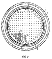
- Figure 2 is a cross-section taken through line II-II shown in Figure 1.
- Figure 3 is a plan view of the upper core plate shown in Figure 2 in the vicinity of the alignment pin.
- Figure 4 is a plan view of a dummy upper core plate as installed in the new core barrel.
- Figure 5 is a plan view from below of the upper core plate shown in Figure 3 with the alignment pin hole locating gage installed.
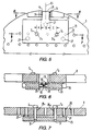
- Figure 6. is a cross-section taken through line VI-VI shown in Figure 5.
- Figure 7 is a cross-section taken through line VII-VII shown in Figure 5.
- Figure 8 is a cross-section taken through line VIII-VIII shown in Figure 1.
- Figure 9 shows the same view as Figure 8, but with the radial support key alignment gage installed.
- Figure 10 is a vertical cross-section in the vicinity of the lower portion of the pressure vessel and core barrel, showing the energy absorber length gage.
- Figure 11 is an isometric view of the radial support key alignment gage shown in Figure 9.
- Figure 12 is a cross-section taken through line XII-XII shown in Figure 1.
- Figure 13 is a vertical cross-section through the containment of the nuclear power plant showing the core barrel positioned above the reactor vessel in the reactor cavity.
- Figure 14 is a flow chart showing the steps for replacing the lower internals.
- Figure 15 is a partially fragmentary elevational view of a simulated lower internals gage in the nuclear reactor vessel shown in Figure 1.
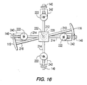
- Figure 16 is a sectional view of the simulated lower internals gage of Figure 15 taken through line XVI-XVI.
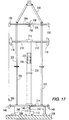
- Figure 17 is a partially fragmentary elevational view of the simulated lower internals gage of Figure 15 located on a stand out of the reactor vessel.
- FIG. 1 a nuclear reactor, such as might be used in a nuclear power plant.
- the reactor is comprised of an approximately cylindrical pressure vessel 1 sealed at its top by an approximately hemispherical closure head 2.
- a reactor core 71 is disposed within the pressure vessel 1.
- the core 71 is comprised of an array of rectangular fuel assemblies 14 (although only four fuel assemblies 14 have been shown in Figure 1 for simplicity, the number of fuel assemblies is actually much greater, as suggested by the array shown in Figure 2).
- a core barrel 5 is also disposed within the vessel 1 and supports and encloses the core 71.
- the core barrel 5 is comprised of a cylindrical portion 72 having an approximately hemispherical bottom 11, a thermal shield 6 surrounding the cylinder 72 in the vicinity of the core 71, a lower core plate 9 on which the fuel assemblies 14 rest, a diffuser plate 10, and a baffle 17 surrounding the fuel assemblies 14 and affixed to the cylinder 72 via formers 70.
- the reactor shown in Figure 1 is typical of those on which the current invention may be practiced.
- a plurality of instrumentation thimble guides 13 penetrate the bottom portion of the vessel 1 and extend through the bottom 11 of the core barrel 5 into the core 71.
- an energy absorber 85 comprised of a plate 12 affixed to support columns 60, is affixed to the bottom 11 of the core barrel 5. The purpose of the energy absorber is to absorb a portion of the impact load should the core barrel 5 drop onto the bottom of the vessel 1 in the event of a failure of the core barrel upper flange.
- the components within the vessel 1 discussed above are typically characterized as the "lower internals” assembly.
- the “upper internals” assembly is comprised of an upper core plate 8, a control rod support plate 56, support columns 4 (only two of which are shown in Figure 1 for simplicity), and control rod guide tubes 52 for each control rod drive shaft 3 (although only two control rod drive shafts 3 are shown in Figure 1 for simplicity, the number of control rods is actually much greater, as shown in Figure 2), and instrumentation thimble guides (not shown) which extend between plates 8 and 56.
- coolant enters inlet nozzles 15, one of which is shown in Figure 1, dispersed about the circumference of the vessel 1 and flows downward through the annular cavity between the core barrel 5 and the vessel 1.
- the coolant then enters the core barrel 5 through holes (not shown) in its bottom 11 and flows upward through the core 71, absorbing heat therefrom.
- the coolant then flows out of the core through holes 74, two of which are shown in Figure 2, in the upper core plate 8.
- the coolant discharges out of the core barrel 5 through discharge nozzles 73, one of which is Figure shown in Figure 1, dispersed about the circumference of the core barrel and thence out of the reactor through discharge nozzles 16 dispersed about circumference of the vessel 1 and aligned with the core barrel discharge nozzles 73.
- the alignment among the vessel, the upper internals and the lower internals in the horizontal direction -- that is, along a plane perpendicular to the longitudinal axis of the reactor -- is set at the top of the core barrel 5.
- This alignment is obtained by a head and vessel alignment pins 50, which are affixed to the core barrel flange 58 by screws 78 and which extends into notches 75 and 76 formed in the control rod support plate flange 59 and the vessel flange 57, respectively.
- This alignment is checked at assembly by measuring the clearance between the pin 50 and the notches 75 and 76 -- typically, the clearance between the pin 50 and the notch 75 should be approximately 0.041 cm (0.016 inch) and the clearance between the pin 50 and the notch 76 should be about 0.081 cm (0.032 inch).
- Four pins 50 are disposed about the circumference of the core barrel flange 58 so that proper alignment is attained in each direction along a plane perpendicular to the longitudinal axis of the reactor.
- the core barrel 5 is also aligned to the pressure vessel 1 at its bottom 11 by a radial support key 32, as shown in Figure 8.
- a specially machined insert 36 having a keyway 35 formed therein, is disposed within a slot formed in a boss 38 protruding radially from the inner surface of the vessel 1.
- the key 32 affixed to a mounting pad 39 formed in a boss 37 protruding radially from the outer surface of the core barrel bottom 11, mates with the keyway 35, thereby aligning the core barrel 5 to the vessel 1.
- Correct alignment of the core barrel 5 is achieved at initial assembly by positioning it within the vessel 1 so that when the head and vessel alignment pins 50 are properly engaged in the notches 76 in the vessel flange 57, the radial gaps between the core barrel discharge nozzles 73 and the pressure vessel discharge nozzles 16 are equalized around the circumference of the reactor. This alignment is then set by custom machining each insert 36 so that the proper clearance between the sides 61, 62 of the key 32 and the sides 63, 64 of the keyway 35 is obtained -- typically, this clearance should be approximately 0.038 cm (0.015 inch).
- Six such keys and keyways are formed about the circumference of the core barrel 5 and vessel 1 to ensure proper alignment in all directions in a plane perpendicular to the longitudinal axis of the reactor. In some plants, there are four such keys and keyways. Note that the base portion of each key 32 is affixed to its mounting pad 39 by screws 33, its location being precisely maintained by a dowel 34.
- each pin 18 penetrates through a hole 79 in the core barrel and extends into a notch 19 formed in the periphery of the upper core plate 8.
- a specially machined insert 20 is mounted in each notch so that a small clearance can be obtained between the sides of the notch 19 and the pin 18 -- typically, this clearance should be approximately 0.015 cm (0.006 inch) at assembly.
- the fuel assemblies 14 are aligned to the upper internals via alignment pins 7 disposed in the upper core plate 8, as shown in Figures 1 and 2.
- Two pins 7 are utilized for each fuel assembly 14.
- Each pin 7 extends into a fuel assembly through a hole 26, shown in Figure 3, in the upper core plate 8.
- the reactor cavity 54 shown in Figure 13 is flooded with water before the upper and lower internals have been removed from the vessel 1.
- the new core barrel 5 is aligned to the vessel 1 at the radial support keys 32 by installing the new core barrel 5 into the pressure vessel 1 with radial support key gages 40, one of which is shown in Figures 9 and 11, mounted on the mounting pads 37 in place of the radial support keys.
- the gage 40 the alignment of the new core barrel 5 to the vessel 1 is determined remotely -- that is, without maintenance personnel having physical access to the key/keyway area.
- a new radial support key 32 is then modified so that its radially extending portion 51 is in the correct location when the key is doweled to the core barrel.
- step 92 the new core barrel 5 is lowered into the vessel with a radial support key gage 40 mounted onto each of the six radial support key mounting pads 37, as shown in Figure 9.
- a dowel 34 extending into a hole in the base portion 80 of the gage 40, serves to accurately locate the gage onto the mounting pad 37.
- six linear voltage differential transformers (LVDTs) 41 are mounted in holes 42 in the sides of the gage 40.
- the lead wires 45 for the LVDTs 41 are lead out of the gage through a vertical hole 44 extending through the gage.
- each LVDT 41 When the core barrel 5 is lowered into the vessel 1, the voltage to each LVDT 41 is maintained so as to keep the LVDT plungers 43 in their retracted positions with the tips of the plungers 43 flush with the surfaces 67, 68 of the gage 40. As can be seen by comparing Figures 8 and 9, the thickness of the radially extending portion of gage 40 is thinner than that of the radial support key 32, so that the gage fits easily into the keyway 35.
- the voltage to each LVDT 41 is increased until the plungers contact the sides 63, 64 of the keyway 35.
- the extension of the plunger can be viewed remotely by an underwater television camera 49, such as that shown in Figure 10 being used for another purpose, to ensure that the plungers properly contact the keyway sides 63, 64.
- the distance which the LVDT plungers traveled, and, therefore, the distance from the each face 67, 68 of the key gage 40 to each side 63, 64 of the keyway 35 can be determined. Combining these distances with the thickness of the radially extending portion of the gage 40, measured conventionally, allows one to determine the width of the keyway 35 and the distance, shown as dimension E in Figures 8 and 9, from the centerline 66 of the keyway to the dowel hole 81 in the boss 37.
- the new lower internals can be customized on-site, as indicated in step 102 of Figure 14.
- Customization is achieved by modifying six new radial support keys 32 so that each is specially adapted to mate with one of the keyways 35. This modification consists of specially machining the keys so that (i) the thickness of the radially extending portion of the key is such that the aforementioned clearance of approximately 0.038 cm (0.015 inch) between the key and the sides of the keyway can be obtained and (ii) the distance from the centerline of the radially extending portion of the key to the dowel hole 69 in the base portion of the key, which serves to locate the key, is such that centerline of the key coincides with the centerline 66 of the keyway, as indicated in Figure 8.
- LVDTs 41 are utilized in the preferred embodiment to remotely measure the distance from the key gage 40 to the sides of the keyway 35, this measurement could also be taken by mechanical means -- for example, by using pins which are mechanically extended using screw threads and which are locked in place by set screws so that their extension can be measure after the core barrel 5 has been removed from the vessel 1.
- Figures 15-17 show an embodiment of the process for taking critical measurements in the pressure vessel which does not use the new lower internals as a gage, but rather a gage which simulates the important features on the replacement internals.
- This aspect of the invention opens up more possibilities for the exchange of lower internals:
- Figure 15 shows a simulated lower internals gage 200 located in a reactor vessel 1 having two outlet nozzles 15 and 16 (represented by one outlet nozzle 15 and one inlet nozzle 16) and four lower radial supports 38.
- the gage 200 have four gage blocks 140 simulating the lower radial support keys 32 shown in Figures 1 and 8 (and used in place of gages 40 shown in Figures 9 and 11) and four gage pins 150 simulating the head and vessel alignment pins 50 of Figures 1 and 12.
- the gage 200 also has two simulated outlet nozzle connections 115 and 116 adjacent vessel outlet nozzles 15 and 16 and a simulated energy absorber base plate 112.
- a rigid main frame 202 including four horizontal members 206 extending from an upper plate the assembly 208 for supporting the gage pins 150, four horizontal members 210 (of which two are shown, extending from a middle plate (represented by one connection 115 and one connection 116) assembly 212 for supporting the simulated outlet connections 115 and 116 and four horizontal members 214 extending from a lower plate assembly 216 for supporting the gage blocks 140.
- These horizontal structural members are reinforced by a hollow central column 220 and four vertical members 222.
- Each of the vertical members 220 and 222 may be fabricated of several flanged short members as is shown or may be one long member.
- the simulated energy absorber base plate 112 is attached at the lower end of a vertical column 230 for slidable movement relative to the hollow central column 220 when the gage 200 is positioned in the reactor vessel 1 shown in Figure 15.
- the vertical column 230 has two large diameter sections 232 and 234 for guiding the column 230 as it moves within the hollow central column 220 and a bore (not shown) within the lower plate assembly 216.
- the lower guiding section 234 is larger than the bore in the lower plate assembly 216 in order to limit relative vertical movement of the simulated energy absorber base plate 112 relative to the main frame 202 as the gage 200 is moved between the reactor vessel 1 and the stand 236 (shown in Figure 17).
- the main frame 202 also has a lift rig 240 for transporting the gage 200 and support legs 242 for providing support on the stand 236.
- the gage blocks 140 are precisely located on the main frame 202 of the gage 200 to extend radially into the vessel keyways 35 shown in Figure 9.
- the gage blocks 140 may deploy the LVDTs 41 shown in Figure 11, and measurements can be taken in the same fashion as when new lower internals are employed to provide the base for these keyway gages.
- the four pins 150 located on the theoretically true centerline of the upper section of the gage to simulate the head and vessel alignment pins 50 shown in Figure 1.
- the gage pins 150 are preferably fit the vessel keyways such that the clearance 76 shown in Figure 12 will be approximately .006 in. (.152 mm) per side rather than the .032 in. (.813 mm) design value.
- the simulated lower internals gage 200 may be leveled and supported at the pressure vessel flange surface where the lower internals assembly flange seats. It is important to note that gage blocks 140 are positioned on the same horizontal centerline as pins 150 above. When gap measurements are then taken in the vessel keyways 76, the centerline of the keys 66 can then be established with respect to the centerline of the keyways 76 in the vessel 1 above, occupied by pins 150. Translated to the replacement lower internals, the lower radial support keys 32 can then be assembled (or modified if already assembled), to coincide with the head and vessel alignment pins 50 in the same relationship as the pressure vessel measurements have dictated, with clearances as specified by the designers.
- gage blocks which are machined to fill the keyway completely with only enough clearance to permit engagement may be employed (not shown); these blocks, rather that being fixed to the simulated lower internals gage 200 can be moved (remotely) along the gage surface and dropped into the vessel keyways and locked in place.)
- the gage 200 can be placed on the reactor cavity operating deck, leveled, and then measurements relating to the centers of the gage blocks to the simulated head and vessel alignment pins 150 above can be made.
- the new core barrel must also be aligned to the upper internals at the upper core plate alignment pins 18.
- this alignment is achieved by determining the location of the notches 19 in the upper core plate 8 relative to the fuel assemblies 14. Since the fuel assemblies are off-loaded during the alignment procedure, the locations of the notches relative to the fuel assemblies is not determined directly. Instead, the locations of the notches relative to the fuel assembly alignment pin holes 26 are determined since their locations are indicative of the locations of the fuel assemblies. This information is then used to locate the holes 79 to be drilled in the new core barrel 5 to retain the alignment pins 18. This procedure ensures that, at final assembly, the fuel assemblies will be properly centered within the baffle 17 of the new core barrel 5.
- the determination of the notch locations is performed in step 94 of Figure 14, after the upper internals have been removed from the vessel in step 89.
- the locations of the notches 19 are determined by mounting an alignment pin gage 25 on the underside of the upper core plate 8 at each notch location, as shown in Figure 5.
- two close clearance holes 31 1 and 31 2 are formed in gage 25. These holes are spaced so as to coincide with two fuel assembly alignment pin holes 26 1 and 26 2 in the upper core plate. This allows the two fuel assembly alignment pins 7 1 and 7 2 to extend into holes 31 1 and 31 2 , respectively, so as to precisely locate the gage on the upper core plate 8.
- Three leveling pads 27, two of which are shown in Figure 7, ensure that the gage rests stably on the underside of the upper core plate 8.
- the alignment pin gage 25 is mounted on the upper core plate 8 so that a tongue 28 emanating from the gage extends into the notch 19, as shown in Figures 5 and 6. Unscrewing two set screws 30 in the tongue 28, releases plungers 29 disposed in either side of the tongue, allowing a spring 82 to drive the plungers against the sides of the notch 19. The set screws 30 are then tightened to lock the plungers 29 into place and the gage 25 is withdrawn from the upper core plate 8.
- the location of the centerline 83 of the notch 19 relative to the holes 31 1 and 31 2 in the gage 25 is determined by measuring (i) the distance from the tip of each plunger 29 to the nearest hole 31, shown as dimensions A and C in Figure 5, and (ii) the distance across the plunger tips, shown as dimension B in Figure 5.
- the measurements obtained above are transferred to a dummy core plate 21, shown in Figure 4.
- the dummy core plate 21 is the same size and shape as the upper core plate 8 and has a plurality of holes 22 formed therein which are the same size as the fuel assembly alignment pin holes 26 in the upper core plate.
- each hole 22 corresponds to one of the outer most fuel assembly alignment pin holes 26 -- that is, to one of the holes 26 closest to the periphery of the upper core plate.
- the location of each hole 22 relative to the dummy core plate 21 is the same as the location of its corresponding fuel assembly alignment pin hole 26 relative to the upper core plate 8.
- the holes 22 in the dummy core plate 21 form a pattern which matches the periphery of the aggregation of fuel assemblies 14 which form the core 71.
- the measurements A, B, and C are transferred onto the dummy core plate 21 and used to locate the centerline 23 of the notch 19 relative to holes 22 1 and 22 2 which correspond to the two holes 26 1 and 26 2 through which the pins 7 1 and 7 2 were inserted to mount the gage 25 on the upper core plate 8, as shown in Figure 4.
- a hole 24 is drilled in the dummy core plate 21 along centerline 23 and, as explained below, is used as a reference point for drilling the hole 79 for the alignment pin 18. This procedure is repeated for each of the four notch 19 locations on the upper core plate 8 so that the dummy core plate 21 has four holes 24, each corresponding to the location of a notch 19 relative to the fuel assembly alignment pin holes 26.
- the dummy core plate 21 is installed into the new core barrel 5, as shown in Figure 4.
- the dummy core plate 21 is positioned in the core barrel 5 so that dummy fuel assembly alignment pins 84, inserted into the holes 22, are spaced equidistance from the baffle 17.
- Holes 24 are then used as reference points for drilling alignment pin holes 79 in the core barrel 5 as part of the customization of the new lower internals, as indicated in step 102 of Figure 14.
- the procedure described above has two important aspects. First, the holes 22 1 and 22 2 used to locate holes 24 correspond with the holes 26 1 and 26 2 used to align the fuel assemblies 14 to the upper core plate. Second, the holes 79, through which the alignment pins 18 extend, were located by centering the holes 22 1 and 22 2 relative to the baffle 17.
- the procedure described above ensures that when the fuel assemblies 14 are installed into the new core barrel 5 and the alignment pins 18 are inserted into the notches 19 in the upper core plate, the fuel assembly alignment pins 7 in the upper core plate will properly align the fuel assemblies to the baffle 17. It should be noted that the clearance between the baffle and the fuel assemblies is only approximately 0.16 cm (0.06 inch), hence the need for careful alignment.
- the alignment measurements on the existing upper core plate 8, taken using the dummy core plate 21, can be taken during a refueling outage prior to the outage during which the lower internals will be replaced, thereby eliminating a considerable amount of time from the lower internals replacement outage.
- the energy absorber 85 shown in Figure 1
- a clearance of approximately 2.84 cm (1.12 inch) is maintained between the plate 12 and the inside surface of the vessel bottom.
- the length of the support columns 60 of the energy absorber 85 is custom fitted to the new core barrel 5. This custom fitting requires that the distance between the core barrel bottom 11 and the vessel bottom be accurately measured. According to the current invention, this measurement is obtained by slidably mounting a gage 46 into the new core barrel, as shown in Figure 10. As shown in Figure 10, a scratch gage 47 and dial indicator 48 are attached to the gage 46.
- the bottom of the gage 46 contacts the vessel bottom so that the gage slides up the core barrel.
- the dial indicator 48 is remotely observed through an underwater television camera 49.
- the reading on dial indicator 48 indicating the distance the gage 46 has slid up the core barrel, is observed.
- the scratch gage 47 provides a permanent record of this indication as a backup.
- step 95 the old lower internals are returned to the reactor cavity after the alignment measurements have been performed on the new lower internals in step 92, so that the disposal work can proceed in parallel with the customization of the new lower internals in step 102.
- the core barrel 5 is supported off the vessel flange 57 by support pedestals 55 attached to the flange --preferably three support pedestals 55 are used.
- the core barrel 5 could be suspended from an I-beam disposed across the top of the reactor cavity 54.
- step 88 the reactor cavity 54 is flooded to a water level 86 such that the depth 87 of water above the vessel flange 57 is greater than the length of the core barrel 5.
- the entire core barrel 5 remains submerged.
- thermal shield 6 Disposal of the thermal shield 6 is performed first in step 96. With the core barrel 5 submerged in the reactor cavity 54, four longitudinal cuts are made in the thermal shield 6, thereby cutting it into four accurate segments. Next, a circumferential cut is made around the thermal shield, thereby creating eight accurate segments which can be conveniently placed into a cask for disposal.
- the underwater cutting of the thermal shield 6 may be done using a plasma arc technique.
- the old lower internals are moved from the position above the vessel 1 and placed in an under water storage stand (not shown) in the reactor cavity 54 in step 97.
- the old lower internals, minus the thermal shield can be reinstalled and the reactor returned to service after fueling for another operating cycle while the new lower internals are being reworked.
- the time required to remove the thermal shield is not added to the critical path.
- this scheduling benefit is obtained without risking a delay in the timely return of the reactor to service should unanticipated problems in the customizing operation arise.
- step 101 the old core barrel 5 is then cut into at least three sections by a series of circumferential cuts. In the preferred embodiment, cuts are made just below the discharge nozzle 73, and just above the lower core plate 9. Since the portion below the lower core plate 9 is the heaviest of the sections, it may be necessary to make further cuts in this section depending on crane capacity. Each section is then placed in a water filled cask for disposal.
- the reactor cavity 54 and vessel 1 are cleaned up and the new lower internals reinstalled in the vessel for final assembly in step 103, the alignment being re-checked during the final assembly process.
Landscapes
- Physics & Mathematics (AREA)
- Engineering & Computer Science (AREA)
- Plasma & Fusion (AREA)
- General Engineering & Computer Science (AREA)
- High Energy & Nuclear Physics (AREA)
- Monitoring And Testing Of Nuclear Reactors (AREA)
Applications Claiming Priority (2)
| Application Number | Priority Date | Filing Date | Title |
|---|---|---|---|
| US692840 | 1996-08-02 | ||
| US08/692,840 US5864594A (en) | 1995-04-18 | 1996-08-02 | Apparatus and method for replacing internal components in a nuclear reactor |
Publications (2)
| Publication Number | Publication Date |
|---|---|
| EP0827158A1 true EP0827158A1 (fr) | 1998-03-04 |
| EP0827158B1 EP0827158B1 (fr) | 2002-04-24 |
Family
ID=24782243
Family Applications (1)
| Application Number | Title | Priority Date | Filing Date |
|---|---|---|---|
| EP97305000A Expired - Lifetime EP0827158B1 (fr) | 1996-08-02 | 1997-07-08 | Dispositif et procédé de remplacement d'équipements internes dans un réacteur nucléaire |
Country Status (5)
| Country | Link |
|---|---|
| US (1) | US5864594A (fr) |
| EP (1) | EP0827158B1 (fr) |
| JP (1) | JP3036688B2 (fr) |
| KR (1) | KR100466149B1 (fr) |
| ES (1) | ES2176620T3 (fr) |
Cited By (2)
| Publication number | Priority date | Publication date | Assignee | Title |
|---|---|---|---|---|
| WO2010064740A1 (fr) * | 2008-12-01 | 2010-06-10 | Korea Hydro & Nuclear Power Co., Ltd. | Appareil et procédé de mesure automatique et à distance des espaces intérieurs d'un réacteur |
| CN112133463A (zh) * | 2020-09-22 | 2020-12-25 | 中广核核电运营有限公司 | 支撑装置、堆内构件支撑组件及支撑装置的安装方法 |
Families Citing this family (15)
| Publication number | Priority date | Publication date | Assignee | Title |
|---|---|---|---|---|
| FR2891655B1 (fr) * | 2005-10-04 | 2007-12-21 | Framatome Anp Sas | Procede et reparation des glissieres d'un ensemble de maintien radial d'une plaque de support de coeur d'un reacteur nucleaire a eau pressurisee. |
| US8638900B2 (en) | 2007-01-02 | 2014-01-28 | Westinghouse Electric Company Llc | Nuclear reactor alignment plate configuration |
| JP5345951B2 (ja) * | 2007-01-02 | 2013-11-20 | ウエスチングハウス・エレクトリック・カンパニー・エルエルシー | 原子炉用アラインメント・プレートの構成 |
| US7616728B2 (en) | 2007-08-24 | 2009-11-10 | Westinghouse Electric Co. Llc | Nuclear reactor internals alignment configuration |
| US8615065B2 (en) * | 2009-10-22 | 2013-12-24 | Westinghouse Electric Company Llc | Modular radial neutron reflector |
| DE102009054913B3 (de) * | 2009-12-17 | 2011-04-07 | Areva Np Gmbh | Verfahren zum Zerlegen eines in einem Reaktordruckbehälter eines Kernkraftwerkes eingebauten unteren Kerngerüstes |
| US10109379B2 (en) * | 2014-06-04 | 2018-10-23 | Westinghouse Electric Company Llc | Control rod guide tube with an extended intermediate guide assembly |
| KR101546884B1 (ko) * | 2014-07-23 | 2015-08-25 | 군산대학교산학협력단 | 피동형 냉각 구조를 구비하는 원자력 발전소의 격납건물 |
| KR101651412B1 (ko) * | 2014-11-20 | 2016-08-26 | 두산중공업 주식회사 | 원자로내부구조물용 노심지지배럴의 정렬구 및 정렬방법 |
| CN106271443A (zh) * | 2016-08-31 | 2017-01-04 | 山东宏达科技集团有限公司 | 乏燃料贮罐罐口及其焊接工艺 |
| CN106271442A (zh) * | 2016-08-31 | 2017-01-04 | 山东宏达科技集团有限公司 | 乏燃料贮罐焊接工艺 |
| FR3068821B1 (fr) * | 2017-07-06 | 2020-08-28 | Electricite De France | Plot de centrage d'un coeur de centrale nucleaire pour cuves de reacteurs |
| KR102021452B1 (ko) * | 2017-08-03 | 2019-09-16 | 한국전력기술 주식회사 | 핵연료 취급을 위한 모듈형 하부 이동 시스템 및 이를 이용한 핵연료 교체방법 |
| CN109961858A (zh) * | 2017-12-22 | 2019-07-02 | 中核核电运行管理有限公司 | 用于压水堆核电站反应堆堆内构件的水下远距离维修工艺 |
| CN109668721B (zh) * | 2019-02-27 | 2024-05-31 | 大连洁能重工股份有限公司 | 一种具有旋转定位功能的试验装置 |
Citations (6)
| Publication number | Priority date | Publication date | Assignee | Title |
|---|---|---|---|---|
| FR2368118A1 (fr) * | 1976-10-18 | 1978-05-12 | Westinghouse Electric Corp | Dispositif d'alignement pour structures internes de cuve de reacteur nucleaire |
| EP0063225A2 (fr) * | 1981-04-08 | 1982-10-27 | Westinghouse Electric Corporation | Appareil pour la contrôle des plaques à chicanes |
| FR2585870A1 (fr) * | 1985-08-02 | 1987-02-06 | Framatome Sa | Procede et dispositif d'adaptation d'equipements internes superieurs neufs sur la cuve d'un reacteur nucleaire a eau sous pression. |
| US4707325A (en) * | 1986-07-03 | 1987-11-17 | Westinghouse Electric Corp. | Gauge plate for use in customizing a replacement upper core plate in a nuclear reactor, and method of using the gauge plate |
| US5149490A (en) * | 1991-12-17 | 1992-09-22 | B&W Nuclear Service Company | Method and apparatus for replacing a nozzle |
| US5490190A (en) * | 1994-12-21 | 1996-02-06 | Westinghouse Electric Corporation | Alignment pin and method for aligning a nuclear fuel assembly with respect to a core plate disposed in a nuclear reactor pressure vessel |
Family Cites Families (2)
| Publication number | Priority date | Publication date | Assignee | Title |
|---|---|---|---|---|
| US4756877A (en) * | 1985-11-06 | 1988-07-12 | Westinghouse Electric Corp. | Core barrel support system for nuclear reactors |
| FR2717608B1 (fr) * | 1994-03-15 | 1996-06-14 | Framatome Sa | Cuve d'un réacteur nucléaire comportant des moyens de maintien de ses équipements internes inférieurs et procédé d'ajustage des moyens de maintien. |
-
1996
- 1996-08-02 US US08/692,840 patent/US5864594A/en not_active Expired - Lifetime
-
1997
- 1997-07-08 ES ES97305000T patent/ES2176620T3/es not_active Expired - Lifetime
- 1997-07-08 EP EP97305000A patent/EP0827158B1/fr not_active Expired - Lifetime
- 1997-07-30 JP JP9204242A patent/JP3036688B2/ja not_active Expired - Lifetime
- 1997-08-01 KR KR1019970036847A patent/KR100466149B1/ko not_active Expired - Lifetime
Patent Citations (6)
| Publication number | Priority date | Publication date | Assignee | Title |
|---|---|---|---|---|
| FR2368118A1 (fr) * | 1976-10-18 | 1978-05-12 | Westinghouse Electric Corp | Dispositif d'alignement pour structures internes de cuve de reacteur nucleaire |
| EP0063225A2 (fr) * | 1981-04-08 | 1982-10-27 | Westinghouse Electric Corporation | Appareil pour la contrôle des plaques à chicanes |
| FR2585870A1 (fr) * | 1985-08-02 | 1987-02-06 | Framatome Sa | Procede et dispositif d'adaptation d'equipements internes superieurs neufs sur la cuve d'un reacteur nucleaire a eau sous pression. |
| US4707325A (en) * | 1986-07-03 | 1987-11-17 | Westinghouse Electric Corp. | Gauge plate for use in customizing a replacement upper core plate in a nuclear reactor, and method of using the gauge plate |
| US5149490A (en) * | 1991-12-17 | 1992-09-22 | B&W Nuclear Service Company | Method and apparatus for replacing a nozzle |
| US5490190A (en) * | 1994-12-21 | 1996-02-06 | Westinghouse Electric Corporation | Alignment pin and method for aligning a nuclear fuel assembly with respect to a core plate disposed in a nuclear reactor pressure vessel |
Cited By (6)
| Publication number | Priority date | Publication date | Assignee | Title |
|---|---|---|---|---|
| WO2010064740A1 (fr) * | 2008-12-01 | 2010-06-10 | Korea Hydro & Nuclear Power Co., Ltd. | Appareil et procédé de mesure automatique et à distance des espaces intérieurs d'un réacteur |
| CN102017009A (zh) * | 2008-12-01 | 2011-04-13 | 韩国水力原子力株式会社 | 自动远程测量反应堆内部间隙的装置和方法 |
| EP2362967A4 (fr) * | 2008-12-01 | 2014-07-16 | Korea Hydro & Nuclear Power Co | Appareil et procédé de mesure automatique et à distance des espaces intérieurs d'un réacteur |
| CN102017009B (zh) * | 2008-12-01 | 2014-07-16 | 韩国水力原子力株式会社 | 自动远程测量反应堆内部间隙的装置和方法 |
| CN112133463A (zh) * | 2020-09-22 | 2020-12-25 | 中广核核电运营有限公司 | 支撑装置、堆内构件支撑组件及支撑装置的安装方法 |
| CN112133463B (zh) * | 2020-09-22 | 2023-02-17 | 中广核核电运营有限公司 | 支撑装置、堆内构件支撑组件及支撑装置的安装方法 |
Also Published As
| Publication number | Publication date |
|---|---|
| JPH1082885A (ja) | 1998-03-31 |
| KR19980018293A (ko) | 1998-06-05 |
| KR100466149B1 (ko) | 2005-03-16 |
| JP3036688B2 (ja) | 2000-04-24 |
| US5864594A (en) | 1999-01-26 |
| EP0827158B1 (fr) | 2002-04-24 |
| ES2176620T3 (es) | 2002-12-01 |
Similar Documents
| Publication | Publication Date | Title |
|---|---|---|
| EP0827158B1 (fr) | Dispositif et procédé de remplacement d'équipements internes dans un réacteur nucléaire | |
| US3817829A (en) | Nuclear reactor internals construction and failed fuel rod detection system | |
| US4696786A (en) | Process and device for adapting new upper internal equipment to the vessel of a pressurized water nuclear reactor | |
| CN1841569B (zh) | 更换核反应堆上部堆内构件中的至少一个热电偶柱的方法和装置 | |
| EP0853807B1 (fr) | Appareil de controle d'ensembles combustibles nucleaires | |
| JPS6327795A (ja) | 上部炉心板用ゲ−ジ板及びその使用方法 | |
| US4862079A (en) | Magnetic method and apparatus for measuring and locating wear of control rods in nuclear reactors | |
| Abdallah et al. | Design, construction and installation of the ATLAS hadronic barrel scintillator-tile calorimeter | |
| KR0178518B1 (ko) | 가압수형 원자로내의 상부 내부 설비의 안내 및 위치 결정 부재의 치수 및 형상 검사를 위한 방법과 장치 | |
| US4601872A (en) | Water sealing device for use in replacing control rod drive housing | |
| US4704801A (en) | Device for checking the vertical alignment of the upper and lower internal equipment of a pressurized water nuclear reactor | |
| JPS6118716B2 (fr) | ||
| JP4221177B2 (ja) | 機器の取扱方法 | |
| EP1067559B1 (fr) | Appareil pour indiquer la croissance induit par irradiation des assemblages de combustible d'un réacteur nucléaire à eau sous pression | |
| JP2016145781A (ja) | 炉内構造物の組立方法 | |
| CN115790370B (zh) | 泵壳法兰形位尺寸测量方法和测量装置 | |
| CN211742662U (zh) | 一种用于燃料组件修复导向机构的高度测量装置 | |
| US6353650B1 (en) | Reduced in-core instrument patterns for pressurized water reactors | |
| KR200339313Y1 (ko) | 핵연료형 원자로 제어봉 와전류 탐상 검사대 | |
| US20010019596A1 (en) | Method and device for measuring a transverse dimension of a spacer-grid of a nuclear fuel assembly | |
| KR100305725B1 (ko) | 14×14 핵연료형 원자로 제어봉 와전류탐상검사대 | |
| CN121953763A (zh) | 一种用于乏燃料贮存格架方管组件的组装检测装置 | |
| Cho et al. | Remote measurements of the dimensions for reactor structure in HANARO | |
| CN120544957A (zh) | 反应堆堆芯组件及其装载方法 | |
| JP2016145785A (ja) | 炉内構造物の組立調整装置および組立方法 |
Legal Events
| Date | Code | Title | Description |
|---|---|---|---|
| PUAI | Public reference made under article 153(3) epc to a published international application that has entered the european phase |
Free format text: ORIGINAL CODE: 0009012 |
|
| AK | Designated contracting states |
Kind code of ref document: A1 Designated state(s): BE CH ES FR GB LI SE |
|
| AX | Request for extension of the european patent |
Free format text: AL;LT;LV;RO;SI |
|
| 17P | Request for examination filed |
Effective date: 19980904 |
|
| AKX | Designation fees paid |
Free format text: BE CH ES FR GB LI SE |
|
| RBV | Designated contracting states (corrected) |
Designated state(s): BE CH ES FR GB LI SE |
|
| REG | Reference to a national code |
Ref country code: DE Ref legal event code: 8566 |
|
| 17Q | First examination report despatched |
Effective date: 20000406 |
|
| RAP1 | Party data changed (applicant data changed or rights of an application transferred) |
Owner name: WESTINGHOUSE ELECTRIC COMPANY LLC |
|
| GRAG | Despatch of communication of intention to grant |
Free format text: ORIGINAL CODE: EPIDOS AGRA |
|
| GRAG | Despatch of communication of intention to grant |
Free format text: ORIGINAL CODE: EPIDOS AGRA |
|
| GRAH | Despatch of communication of intention to grant a patent |
Free format text: ORIGINAL CODE: EPIDOS IGRA |
|
| REG | Reference to a national code |
Ref country code: GB Ref legal event code: IF02 |
|
| GRAH | Despatch of communication of intention to grant a patent |
Free format text: ORIGINAL CODE: EPIDOS IGRA |
|
| GRAA | (expected) grant |
Free format text: ORIGINAL CODE: 0009210 |
|
| AK | Designated contracting states |
Kind code of ref document: B1 Designated state(s): BE CH ES FR GB LI SE |
|
| REG | Reference to a national code |
Ref country code: GB Ref legal event code: FG4D |
|
| REG | Reference to a national code |
Ref country code: CH Ref legal event code: EP |
|
| REG | Reference to a national code |
Ref country code: CH Ref legal event code: NV Representative=s name: A. BRAUN, BRAUN, HERITIER, ESCHMANN AG PATENTANWAE |
|
| ET | Fr: translation filed | ||
| REG | Reference to a national code |
Ref country code: ES Ref legal event code: FG2A Ref document number: 2176620 Country of ref document: ES Kind code of ref document: T3 |
|
| PLBE | No opposition filed within time limit |
Free format text: ORIGINAL CODE: 0009261 |
|
| STAA | Information on the status of an ep patent application or granted ep patent |
Free format text: STATUS: NO OPPOSITION FILED WITHIN TIME LIMIT |
|
| 26N | No opposition filed |
Effective date: 20030127 |
|
| REG | Reference to a national code |
Ref country code: CH Ref legal event code: PFA Owner name: WESTINGHOUSE ELECTRIC COMPANY LLC Free format text: WESTINGHOUSE ELECTRIC COMPANY LLC#4350 NORTHERN PIKE#MONROEVILLE, PA 15146-2866 (US) -TRANSFER TO- WESTINGHOUSE ELECTRIC COMPANY LLC#4350 NORTHERN PIKE#MONROEVILLE, PA 15146-2866 (US) |
|
| REG | Reference to a national code |
Ref country code: CH Ref legal event code: PCAR Free format text: NEW ADDRESS: HOLBEINSTRASSE 36-38, 4051 BASEL (CH) |
|
| REG | Reference to a national code |
Ref country code: FR Ref legal event code: PLFP Year of fee payment: 20 |
|
| PGFP | Annual fee paid to national office [announced via postgrant information from national office to epo] |
Ref country code: GB Payment date: 20160624 Year of fee payment: 20 |
|
| PGFP | Annual fee paid to national office [announced via postgrant information from national office to epo] |
Ref country code: FR Payment date: 20160621 Year of fee payment: 20 |
|
| PGFP | Annual fee paid to national office [announced via postgrant information from national office to epo] |
Ref country code: CH Payment date: 20160725 Year of fee payment: 20 |
|
| PGFP | Annual fee paid to national office [announced via postgrant information from national office to epo] |
Ref country code: SE Payment date: 20160708 Year of fee payment: 20 |
|
| PGFP | Annual fee paid to national office [announced via postgrant information from national office to epo] |
Ref country code: BE Payment date: 20160714 Year of fee payment: 20 Ref country code: ES Payment date: 20160708 Year of fee payment: 20 |
|
| REG | Reference to a national code |
Ref country code: CH Ref legal event code: PL |
|
| REG | Reference to a national code |
Ref country code: GB Ref legal event code: PE20 Expiry date: 20170707 |
|
| PG25 | Lapsed in a contracting state [announced via postgrant information from national office to epo] |
Ref country code: GB Free format text: LAPSE BECAUSE OF EXPIRATION OF PROTECTION Effective date: 20170707 |
|
| REG | Reference to a national code |
Ref country code: ES Ref legal event code: FD2A Effective date: 20180508 |
|
| PG25 | Lapsed in a contracting state [announced via postgrant information from national office to epo] |
Ref country code: ES Free format text: LAPSE BECAUSE OF EXPIRATION OF PROTECTION Effective date: 20170709 |