EP0827251A2 - Interrupteur électrique à basse tension - Google Patents
Interrupteur électrique à basse tension Download PDFInfo
- Publication number
- EP0827251A2 EP0827251A2 EP97114682A EP97114682A EP0827251A2 EP 0827251 A2 EP0827251 A2 EP 0827251A2 EP 97114682 A EP97114682 A EP 97114682A EP 97114682 A EP97114682 A EP 97114682A EP 0827251 A2 EP0827251 A2 EP 0827251A2
- Authority
- EP
- European Patent Office
- Prior art keywords
- evaluation unit
- low
- switching device
- voltage switching
- sensor
- Prior art date
- Legal status (The legal status is an assumption and is not a legal conclusion. Google has not performed a legal analysis and makes no representation as to the accuracy of the status listed.)
- Granted
Links
Images
Classifications
-
- H—ELECTRICITY
- H02—GENERATION; CONVERSION OR DISTRIBUTION OF ELECTRIC POWER
- H02H—EMERGENCY PROTECTIVE CIRCUIT ARRANGEMENTS
- H02H7/00—Emergency protective circuit arrangements specially adapted for specific types of electric machines or apparatus or for sectionalised protection of cable or line systems, and effecting automatic switching in the event of an undesired change from normal working conditions
- H02H7/08—Emergency protective circuit arrangements specially adapted for specific types of electric machines or apparatus or for sectionalised protection of cable or line systems, and effecting automatic switching in the event of an undesired change from normal working conditions for dynamo-electric motors
- H02H7/0816—Emergency protective circuit arrangements specially adapted for specific types of electric machines or apparatus or for sectionalised protection of cable or line systems, and effecting automatic switching in the event of an undesired change from normal working conditions for dynamo-electric motors concerning the starting sequence, e.g. limiting the number of starts per time unit, monitoring speed during starting
-
- H—ELECTRICITY
- H01—ELECTRIC ELEMENTS
- H01H—ELECTRIC SWITCHES; RELAYS; SELECTORS; EMERGENCY PROTECTIVE DEVICES
- H01H71/00—Details of the protective switches or relays covered by groups H01H73/00 - H01H83/00
- H01H71/10—Operating or release mechanisms
- H01H71/12—Automatic release mechanisms with or without manual release
- H01H71/123—Automatic release mechanisms with or without manual release using a solid-state trip unit
- H01H2071/124—Automatic release mechanisms with or without manual release using a solid-state trip unit with a hybrid structure, the solid state trip device being combined with a thermal or a electromagnetic trip
-
- H—ELECTRICITY
- H01—ELECTRIC ELEMENTS
- H01H—ELECTRIC SWITCHES; RELAYS; SELECTORS; EMERGENCY PROTECTIVE DEVICES
- H01H89/00—Combinations of two or more different basic types of electric switches, relays, selectors and emergency protective devices, not covered by any single one of the other main groups of this subclass
- H01H89/06—Combination of a manual reset circuit with a contactor, i.e. the same circuit controlled by both a protective and a remote control device
- H01H2089/065—Coordination between protection and remote control, e.g. protection job repartition, mutual assistance or monitoring
-
- H—ELECTRICITY
- H01—ELECTRIC ELEMENTS
- H01H—ELECTRIC SWITCHES; RELAYS; SELECTORS; EMERGENCY PROTECTIVE DEVICES
- H01H2300/00—Orthogonal indexing scheme relating to electric switches, relays, selectors or emergency protective devices covered by H01H
- H01H2300/03—Application domotique, e.g. for house automation, bus connected switches, sensors, loads or intelligent wiring
-
- H—ELECTRICITY
- H01—ELECTRIC ELEMENTS
- H01H—ELECTRIC SWITCHES; RELAYS; SELECTORS; EMERGENCY PROTECTIVE DEVICES
- H01H71/00—Details of the protective switches or relays covered by groups H01H73/00 - H01H83/00
- H01H71/10—Operating or release mechanisms
- H01H71/12—Automatic release mechanisms with or without manual release
- H01H71/123—Automatic release mechanisms with or without manual release using a solid-state trip unit
-
- H—ELECTRICITY
- H01—ELECTRIC ELEMENTS
- H01H—ELECTRIC SWITCHES; RELAYS; SELECTORS; EMERGENCY PROTECTIVE DEVICES
- H01H71/00—Details of the protective switches or relays covered by groups H01H73/00 - H01H83/00
- H01H71/10—Operating or release mechanisms
- H01H71/12—Automatic release mechanisms with or without manual release
- H01H71/24—Electromagnetic mechanisms
- H01H71/2409—Electromagnetic mechanisms combined with an electromagnetic current limiting mechanism
-
- H—ELECTRICITY
- H01—ELECTRIC ELEMENTS
- H01H—ELECTRIC SWITCHES; RELAYS; SELECTORS; EMERGENCY PROTECTIVE DEVICES
- H01H89/00—Combinations of two or more different basic types of electric switches, relays, selectors and emergency protective devices, not covered by any single one of the other main groups of this subclass
- H01H89/06—Combination of a manual reset circuit with a contactor, i.e. the same circuit controlled by both a protective and a remote control device
- H01H89/08—Combination of a manual reset circuit with a contactor, i.e. the same circuit controlled by both a protective and a remote control device with both devices using the same contact pair
-
- Y—GENERAL TAGGING OF NEW TECHNOLOGICAL DEVELOPMENTS; GENERAL TAGGING OF CROSS-SECTIONAL TECHNOLOGIES SPANNING OVER SEVERAL SECTIONS OF THE IPC; TECHNICAL SUBJECTS COVERED BY FORMER USPC CROSS-REFERENCE ART COLLECTIONS [XRACs] AND DIGESTS
- Y02—TECHNOLOGIES OR APPLICATIONS FOR MITIGATION OR ADAPTATION AGAINST CLIMATE CHANGE
- Y02B—CLIMATE CHANGE MITIGATION TECHNOLOGIES RELATED TO BUILDINGS, e.g. HOUSING, HOUSE APPLIANCES OR RELATED END-USER APPLICATIONS
- Y02B90/00—Enabling technologies or technologies with a potential or indirect contribution to GHG emissions mitigation
- Y02B90/20—Smart grids as enabling technology in buildings sector
-
- Y—GENERAL TAGGING OF NEW TECHNOLOGICAL DEVELOPMENTS; GENERAL TAGGING OF CROSS-SECTIONAL TECHNOLOGIES SPANNING OVER SEVERAL SECTIONS OF THE IPC; TECHNICAL SUBJECTS COVERED BY FORMER USPC CROSS-REFERENCE ART COLLECTIONS [XRACs] AND DIGESTS
- Y04—INFORMATION OR COMMUNICATION TECHNOLOGIES HAVING AN IMPACT ON OTHER TECHNOLOGY AREAS
- Y04S—SYSTEMS INTEGRATING TECHNOLOGIES RELATED TO POWER NETWORK OPERATION, COMMUNICATION OR INFORMATION TECHNOLOGIES FOR IMPROVING THE ELECTRICAL POWER GENERATION, TRANSMISSION, DISTRIBUTION, MANAGEMENT OR USAGE, i.e. SMART GRIDS
- Y04S20/00—Management or operation of end-user stationary applications or the last stages of power distribution; Controlling, monitoring or operating thereof
- Y04S20/14—Protecting elements, switches, relays or circuit breakers
Definitions
- the invention relates to an electrical low-voltage switching device according to the preamble of claim 1.
- Such a low-voltage switching device has become known from DE 43 35 965 A1.
- This switching device comprises a line-side circuit breaker and a line-side circuit breaker Contactors that are housed in a switch housing and the same Have lift-off currents.
- a sensor In line with the circuit breaker and the contactor and between the two is a sensor whose output signals are one Electronics can be supplied, which are a bimetal release, a quick release electromagnetic Type and another electromagnetic release, the latter as an instantaneous trigger.
- the two electromagnetic triggers work on the circuit breaker of the circuit breaker and on the contactor at the same time a.
- the object of the invention is to provide a low-voltage switching device of the type mentioned To create kind, which is simplified compared to the known.
- a contact set a first sensor and an electromagnet, preferably an impact anchor system, which are also in a row.
- the contact set is suitable for switching off load and overcurrents; the first sensor measures the low overcurrents and medium short-circuit currents, its signals being one Electronic evaluation unit can be fed, which ensures that with these Stream the contact set is opened.
- the impact anchor system is for high short-circuit currents provided that opens the contact set directly or via a key switch.
- a further embodiment of the invention can be that a second sensor is used in the current path, which is used for voltage measurement and whose output signals can also be fed to the evaluation unit.
- this second sensor undervoltage can be detected, on the one hand, and, in addition, the signals coming from the first and second sensor can be detected in the evaluation unit for detection, for. B. the engine load with cos ⁇ to be used; the evaluation unit then switches the motor when a certain level is exceeded or undershot cos ⁇ -wer tes from.
- the first sensor can be a current transformer, which also serves to power the evaluation unit.
- the electronic evaluation unit have a microprocessor with which the sensor signals can be evaluated.
- the evaluation unit can control a relay, with which the contact set can be operated as a contactor.
- the relay can also from Switch lock can be controlled.
- one of the switch locks and the other can be actuated by the evaluation unit.
- the switch arrangement can have mechanical and / or electronic interruption points exhibit.
- the relay can also be controlled by remote control via the evaluation unit be.
- a bus connection for a bus line to the Remote, on, off, for control and / or for remote display of the evaluation unit processed signals is also provided.
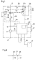
- An electrical low-voltage switching device which has the reference number 10, has a main current path 11, which is drawn in Fig. 1 single phase, but which is also multi-phase can be, with terminals 12 and 13.
- a main current path 11 In the main current path 11 are in Row the coil 14 of an impact magnet system, a contact set 15, a first Sensor 16 for measuring the current flowing through the main current path 11 and a second sensor 17 for voltage measurement.
- the impact anchor magnet system with the Coil 14 acts via the line of action 18 directly on the contact set 15 as well as on Switch lock 19 via an action line 20.
- the contact set 15 acts via an action line 40 a relay 21, whereby a contactor function is achieved.
- the relay 21 is in one switched on via control terminals 22a, 22b of voltage-carrying control line 22, which contains a control switch 23 in series with the relay 21, for example a electronic switch, e.g. B. a transistor, or a mechanical switch or which can consist of two contact or break points 23a and 23b, see further below Fig. 2.
- the control switch 23 can also over an effective line 41 from Switch lock 19 are operated.
- the output signals of the first sensor 16 are sent via a line 24 to an evaluation unit 25 supplied, as well as the signals of the voltage sensor 17, which over a line 26 of the evaluation unit 25 are supplied. With certain low-voltage switchgear such a voltage sensor would not be required.
- the evaluation unit 25 contains a microprocessor 27 and in the evaluation unit 25 becomes a bimetal release and an electromagnetic release for medium short-circuit currents simulated; the high short-circuit currents are caused by the hammer magnet system switched off with the coil 14, the impact anchor directly on the movable Part of the contact set also hits the key switch.
- the switching mechanism 19 is actuated via an effective line 28, so that the contact set 15 is permanently open.
- the switch 23 can be closed via the line of action 32, so that the Contact set 15 can be opened via the relay 21 and the line of action 40.
- the low-voltage switching device can be actuated via the central control unit 31 namely for a control or contactor function and a switch-off function; to achieve A control contactor function includes the evaluation unit 25 via the line of action 32 connected to the switch 23.
- the evaluation unit 25 are only designed for simple overload protection the microprocessor 27 is not required and the evaluation unit 25 can can be supplied with the current of the sensor 16. In the case when a microprocessor 27 is present, there is an additional power supply (not shown) for the evaluation unit 25 necessary.
- the current sensor 16 is configured in a suitable manner, then the current sensor can as a current transformer at the same time to supply the evaluation unit 25 can be used.
- the contact set 15 can be a contact point with a contact lever on which a movable Contact piece is arranged, and a fixed contact piece, or a double contact point with two fixed contact pieces and two attached to a contact bridge have movable contact pieces.
- the switch 23 can also, as shown in Fig. 2, by two contact points 23a and 23b be formed; the evaluation unit 25 acts on the one contact point 23a via the Line of action 32, and on the other contact point 23b, the switch lock acts on the Line of action 41.
- Both lines of action can, as shown in FIG. 1, also on a contact point act, and in the embodiment of FIG. 2, the contact point 23a is mechanical and the contact point 23b electronically; the contact point can of course also 23b can also be formed by a mechanical switch.
- the central control unit 31 can be used as a programmable logic controller (PLC) be trained.
- PLC programmable logic controller
- the evaluation unit 25 can be one Activate the shunt release, not shown, which the switching lock 19th triggers and opens the contact set 15.
- the switch 19th triggers and opens the contact set 15.
- the key switch can also be opened via the line of action 28.
- the evaluation unit 25 can be operated by the central control unit 31 or reset by means of a switch button 42 on site. If the switch lock 19 has triggered, then the key switch can be made via a switch 43 be turned on; in this case, the evaluation unit is via an inverted line of action 28 25 reset.
- the remote operator 29 can be operated manually; the evaluation unit 25 and thus that Low-voltage switch device 10 can be switched on manually via the remote drive 29 will.
- the evaluation circuit 25 gives a pulse via the line of action 32 to the switch 23 so that the relay 21 over the line of action 40 the contact point closes.
- evaluation unit 25 For example whether undervoltage is present on line 11 or whether there is an overcurrent; it is also possible to simulate an engine load monitor.
- an engine load monitor is a cos ⁇ evaluation unit advises , through which the cos ⁇ is measured. If certain cos ⁇ values a signal is generated, as well as when an overload is detected. If e.g. B. a V-belt breaks in an engine fan, then this is detected and the senselessly running engine is switched off.
- the current transformer 16 can also be designed as a current transformer, so that the electronics of the evaluation unit 25 are supplied with current.
Landscapes
- Keying Circuit Devices (AREA)
- Emergency Protection Circuit Devices (AREA)
- Protection Of Generators And Motors (AREA)
- Relay Circuits (AREA)
Applications Claiming Priority (2)
| Application Number | Priority Date | Filing Date | Title |
|---|---|---|---|
| DE19635055A DE19635055A1 (de) | 1996-08-30 | 1996-08-30 | Elektrisches Niederspannungsschaltgerät |
| DE19635055 | 1996-08-30 |
Publications (3)
| Publication Number | Publication Date |
|---|---|
| EP0827251A2 true EP0827251A2 (fr) | 1998-03-04 |
| EP0827251A3 EP0827251A3 (fr) | 1999-04-21 |
| EP0827251B1 EP0827251B1 (fr) | 2006-12-27 |
Family
ID=7804096
Family Applications (1)
| Application Number | Title | Priority Date | Filing Date |
|---|---|---|---|
| EP97114682A Expired - Lifetime EP0827251B1 (fr) | 1996-08-30 | 1997-08-25 | Interrupteur électrique à basse tension |
Country Status (2)
| Country | Link |
|---|---|
| EP (1) | EP0827251B1 (fr) |
| DE (2) | DE19635055A1 (fr) |
Cited By (4)
| Publication number | Priority date | Publication date | Assignee | Title |
|---|---|---|---|---|
| WO2001097243A1 (fr) * | 2000-06-13 | 2001-12-20 | Eaton Corporation | Disjoncteur d'interrupteur de courant de defaut d'arc/d'interrupteur de courant de defaut a la terre pourvu d'un mecanisme a securite integree |
| WO2005086311A1 (fr) * | 2004-03-04 | 2005-09-15 | Siemens Aktiengesellschaft | Dispositif de protection destine a un branchement de recepteur |
| WO2008028432A1 (fr) * | 2006-09-07 | 2008-03-13 | Siemens Aktiengesellschaft | Appareil de commutation, notamment dispositif d'amorçage compact |
| WO2011027120A3 (fr) * | 2009-09-03 | 2011-06-16 | Eaton Industries Manufacturing Gmbh | Disjoncteur miniature |
Families Citing this family (1)
| Publication number | Priority date | Publication date | Assignee | Title |
|---|---|---|---|---|
| DE102008018257A1 (de) * | 2008-03-31 | 2009-10-08 | Siemens Aktiengesellschaft | Elektronisches Schaltgerät, insbesondere Kompaktstarter oder Kompaktwendestarter |
Family Cites Families (9)
| Publication number | Priority date | Publication date | Assignee | Title |
|---|---|---|---|---|
| DE2600472C3 (de) * | 1976-01-08 | 1981-12-10 | Siemens AG, 1000 Berlin und 8000 München | Überlastschutzeinrichtung für eine elektrische Maschine |
| FR2516304A1 (fr) * | 1981-11-09 | 1983-05-13 | Telemecanique Electrique | Interrupteur a commande mecanique et ouverture automatique |
| US4680562A (en) * | 1985-07-29 | 1987-07-14 | Westinghouse Electric Corp. | Integral circuit interrupter with separable modules |
| GB2246909B (en) * | 1990-07-16 | 1995-02-22 | Terasaki Denki Sangyo Kk | Circuit breaker including forced contact parting mechanism capable of self-retaining under short circuit condition |
| US5369542A (en) * | 1992-03-06 | 1994-11-29 | Siemens Energy & Automation, Inc. | Dual trip circuit for circuit breaker |
| FR2707794B1 (fr) * | 1993-07-12 | 1995-08-18 | Telemecanique | Appareil interrupteur de protection. |
| DE4335965A1 (de) * | 1993-10-21 | 1995-04-27 | Licentia Gmbh | Motorstarter mit integriertem Kurzschlußschutz |
| DE9404335U1 (de) * | 1994-03-15 | 1994-08-25 | G.J. Bohnenstiel GmbH, 69126 Heidelberg | Vorrichtung zur Überlasterkennung eines elektrischen Wechsel- oder Drehstrommotors |
| DE4445961A1 (de) * | 1994-12-22 | 1996-06-27 | Licentia Gmbh | Steuereinheit für elektrische Lasten, insbesondere für Motoren |
-
1996
- 1996-08-30 DE DE19635055A patent/DE19635055A1/de not_active Withdrawn
-
1997
- 1997-08-25 EP EP97114682A patent/EP0827251B1/fr not_active Expired - Lifetime
- 1997-08-25 DE DE59712782T patent/DE59712782D1/de not_active Expired - Lifetime
Cited By (7)
| Publication number | Priority date | Publication date | Assignee | Title |
|---|---|---|---|---|
| WO2001097243A1 (fr) * | 2000-06-13 | 2001-12-20 | Eaton Corporation | Disjoncteur d'interrupteur de courant de defaut d'arc/d'interrupteur de courant de defaut a la terre pourvu d'un mecanisme a securite integree |
| AU772359B2 (en) * | 2000-06-13 | 2004-04-22 | Eaton Corporation | Ground fault current interrupter/arc fault current interrupter circuit breaker with fail safe mechanism |
| WO2005086311A1 (fr) * | 2004-03-04 | 2005-09-15 | Siemens Aktiengesellschaft | Dispositif de protection destine a un branchement de recepteur |
| WO2008028432A1 (fr) * | 2006-09-07 | 2008-03-13 | Siemens Aktiengesellschaft | Appareil de commutation, notamment dispositif d'amorçage compact |
| WO2011027120A3 (fr) * | 2009-09-03 | 2011-06-16 | Eaton Industries Manufacturing Gmbh | Disjoncteur miniature |
| US8766749B2 (en) | 2009-09-03 | 2014-07-01 | Eaton Industries Manufacturing Gmbh | Miniature circuit breaker |
| EA021455B1 (ru) * | 2009-09-03 | 2015-06-30 | Итон Индастриз Мэньюфэкчуринг Гмбх | Миниатюрный размыкатель цепи |
Also Published As
| Publication number | Publication date |
|---|---|
| EP0827251A3 (fr) | 1999-04-21 |
| EP0827251B1 (fr) | 2006-12-27 |
| DE59712782D1 (de) | 2007-02-08 |
| DE19635055A1 (de) | 1998-03-05 |
Similar Documents
| Publication | Publication Date | Title |
|---|---|---|
| DE3783704T2 (de) | Mehrpoliger differentialmodulschutzschalter. | |
| EP1186084A1 (fr) | Dispositif de coupure electrique pour la protection contre les surintensites | |
| EP0156184A2 (fr) | Pièce additionnelle pour un disjoncteur de puissance avec un déclencheur à courant de travail | |
| DE4034485A1 (de) | Niederspannungsschaltgeraet | |
| DE2847976A1 (de) | Erdschlussfehler-schutzeinrichtung fuer industrielle leistungsschaltungen | |
| DE10244961B3 (de) | Selektiver Leitungsschutzschalter | |
| EP0827251B1 (fr) | Interrupteur électrique à basse tension | |
| DE102019103036B4 (de) | Ladesäule mit einem Kombi-Schaltmodul | |
| DE19529474C1 (de) | Verfahren und Anordnung zur automatischen Überwachung von Fehlerstromschutzschaltern | |
| DE19733268C2 (de) | Verfahren und Einrichtung zum Detektieren von Überströmen in einer Schaltanlage | |
| DE2531707A1 (de) | Verfahren zum wegschalten eines kurzschlussbehafteten netzteiles aus einem geschlossenen elektrischen ringnetz und schalter zur durchfuehrung des verfahrens | |
| DE69409356T2 (de) | Prüfeinrichtung für Differentialschutzschalter und diese Vorrichtung enthaltende Differentialschutzschalter | |
| EP1065690A2 (fr) | Déclencheur sélectif | |
| DE10254038A1 (de) | Hilfsauslöser für Motorschutzschalter | |
| DE10255168A1 (de) | Schutzschalter | |
| EP0676844B1 (fr) | Coupe-circuit auto-surveillant en cas de défaut à la masse | |
| DE10148155A1 (de) | Anordnung zur Überwachung von Motorstartern | |
| DE102004011025A1 (de) | Niederspannungs-Leistungsschalter mit elektronischem Überstromauslöser und einer Betriebszustands-Erkennungseinrichtung | |
| DE4322845A1 (de) | Anordnung zur Messung von Fehlerströmen in Verbraucherstromkreisen oder dergleichen | |
| DE102004046810A1 (de) | Elektronischer Schutzschalter mit einstellbarer Auslösecharakteristik | |
| EP0019904A1 (fr) | Relais de surcharge de protection | |
| DE10246479B4 (de) | Niederspannungs-Leistungsschalter mit zusätzlicher Schnellauslösung | |
| DE1588644C3 (de) | Schaltungsanordnung zur selbsttätigen kontinuierlichen Überwachung eines ungeerdeten elektrischen, einem Energiestromkreis zugeordneten Sicherheitskreises auf Erdsch lußströme | |
| DE202004014580U1 (de) | Elektronischer Schutzschalter mit einstellbarer Auslöse-Charakteristik | |
| DE3815358C2 (de) | Sicherheitsnotausschaltung für Schützabzweige mit vorgeschaltetem Leistungsschalter |
Legal Events
| Date | Code | Title | Description |
|---|---|---|---|
| PUAI | Public reference made under article 153(3) epc to a published international application that has entered the european phase |
Free format text: ORIGINAL CODE: 0009012 |
|
| AK | Designated contracting states |
Kind code of ref document: A2 Designated state(s): DE ES FR GB IT NL SE |
|
| PUAL | Search report despatched |
Free format text: ORIGINAL CODE: 0009013 |
|
| AK | Designated contracting states |
Kind code of ref document: A3 Designated state(s): AT BE CH DE DK ES FI FR GB GR IE IT LI LU MC NL PT SE |
|
| 17P | Request for examination filed |
Effective date: 19991014 |
|
| AKX | Designation fees paid |
Free format text: DE ES FR GB IT NL SE |
|
| 17Q | First examination report despatched |
Effective date: 20000420 |
|
| RAP1 | Party data changed (applicant data changed or rights of an application transferred) |
Owner name: ABB PATENT GMBH |
|
| GRAP | Despatch of communication of intention to grant a patent |
Free format text: ORIGINAL CODE: EPIDOSNIGR1 |
|
| GRAS | Grant fee paid |
Free format text: ORIGINAL CODE: EPIDOSNIGR3 |
|
| GRAA | (expected) grant |
Free format text: ORIGINAL CODE: 0009210 |
|
| AK | Designated contracting states |
Kind code of ref document: B1 Designated state(s): DE ES FR GB IT NL SE |
|
| PG25 | Lapsed in a contracting state [announced via postgrant information from national office to epo] |
Ref country code: NL Free format text: LAPSE BECAUSE OF FAILURE TO SUBMIT A TRANSLATION OF THE DESCRIPTION OR TO PAY THE FEE WITHIN THE PRESCRIBED TIME-LIMIT Effective date: 20061227 |
|
| REG | Reference to a national code |
Ref country code: GB Ref legal event code: FG4D Free format text: NOT ENGLISH |
|
| REF | Corresponds to: |
Ref document number: 59712782 Country of ref document: DE Date of ref document: 20070208 Kind code of ref document: P |
|
| PG25 | Lapsed in a contracting state [announced via postgrant information from national office to epo] |
Ref country code: SE Free format text: LAPSE BECAUSE OF FAILURE TO SUBMIT A TRANSLATION OF THE DESCRIPTION OR TO PAY THE FEE WITHIN THE PRESCRIBED TIME-LIMIT Effective date: 20070327 |
|
| PG25 | Lapsed in a contracting state [announced via postgrant information from national office to epo] |
Ref country code: ES Free format text: LAPSE BECAUSE OF FAILURE TO SUBMIT A TRANSLATION OF THE DESCRIPTION OR TO PAY THE FEE WITHIN THE PRESCRIBED TIME-LIMIT Effective date: 20070407 |
|
| ET | Fr: translation filed | ||
| NLV1 | Nl: lapsed or annulled due to failure to fulfill the requirements of art. 29p and 29m of the patents act | ||
| GBV | Gb: ep patent (uk) treated as always having been void in accordance with gb section 77(7)/1977 [no translation filed] |
Effective date: 20061227 |
|
| PLBE | No opposition filed within time limit |
Free format text: ORIGINAL CODE: 0009261 |
|
| STAA | Information on the status of an ep patent application or granted ep patent |
Free format text: STATUS: NO OPPOSITION FILED WITHIN TIME LIMIT |
|
| PG25 | Lapsed in a contracting state [announced via postgrant information from national office to epo] |
Ref country code: GB Free format text: LAPSE BECAUSE OF FAILURE TO SUBMIT A TRANSLATION OF THE DESCRIPTION OR TO PAY THE FEE WITHIN THE PRESCRIBED TIME-LIMIT Effective date: 20061227 |
|
| 26N | No opposition filed |
Effective date: 20070928 |
|
| PGFP | Annual fee paid to national office [announced via postgrant information from national office to epo] |
Ref country code: FR Payment date: 20110901 Year of fee payment: 15 |
|
| PGFP | Annual fee paid to national office [announced via postgrant information from national office to epo] |
Ref country code: IT Payment date: 20110824 Year of fee payment: 15 |
|
| PGFP | Annual fee paid to national office [announced via postgrant information from national office to epo] |
Ref country code: DE Payment date: 20120822 Year of fee payment: 16 |
|
| REG | Reference to a national code |
Ref country code: FR Ref legal event code: ST Effective date: 20130430 |
|
| PG25 | Lapsed in a contracting state [announced via postgrant information from national office to epo] |
Ref country code: IT Free format text: LAPSE BECAUSE OF NON-PAYMENT OF DUE FEES Effective date: 20120825 |
|
| PG25 | Lapsed in a contracting state [announced via postgrant information from national office to epo] |
Ref country code: FR Free format text: LAPSE BECAUSE OF NON-PAYMENT OF DUE FEES Effective date: 20120831 |
|
| PG25 | Lapsed in a contracting state [announced via postgrant information from national office to epo] |
Ref country code: DE Free format text: LAPSE BECAUSE OF NON-PAYMENT OF DUE FEES Effective date: 20140301 |
|
| REG | Reference to a national code |
Ref country code: DE Ref legal event code: R119 Ref document number: 59712782 Country of ref document: DE Effective date: 20140301 |