EP0827454B1 - Dispositif de coupe - Google Patents
Dispositif de coupe Download PDFInfo
- Publication number
- EP0827454B1 EP0827454B1 EP96914073A EP96914073A EP0827454B1 EP 0827454 B1 EP0827454 B1 EP 0827454B1 EP 96914073 A EP96914073 A EP 96914073A EP 96914073 A EP96914073 A EP 96914073A EP 0827454 B1 EP0827454 B1 EP 0827454B1
- Authority
- EP
- European Patent Office
- Prior art keywords
- cutting
- cylinder
- knife
- cutting device
- cutting knife
- Prior art date
- Legal status (The legal status is an assumption and is not a legal conclusion. Google has not performed a legal analysis and makes no representation as to the accuracy of the status listed.)
- Expired - Lifetime
Links
- 238000005520 cutting process Methods 0.000 title claims abstract description 97
- 125000006850 spacer group Chemical group 0.000 claims description 7
- 238000006073 displacement reaction Methods 0.000 claims description 4
- 239000000969 carrier Substances 0.000 description 1
- 230000010363 phase shift Effects 0.000 description 1
Images


Classifications
-
- B—PERFORMING OPERATIONS; TRANSPORTING
- B65—CONVEYING; PACKING; STORING; HANDLING THIN OR FILAMENTARY MATERIAL
- B65H—HANDLING THIN OR FILAMENTARY MATERIAL, e.g. SHEETS, WEBS, CABLES
- B65H45/00—Folding thin material
- B65H45/12—Folding articles or webs with application of pressure to define or form crease lines
- B65H45/28—Folding in combination with cutting
-
- B—PERFORMING OPERATIONS; TRANSPORTING
- B26—HAND CUTTING TOOLS; CUTTING; SEVERING
- B26D—CUTTING; DETAILS COMMON TO MACHINES FOR PERFORATING, PUNCHING, CUTTING-OUT, STAMPING-OUT OR SEVERING
- B26D1/00—Cutting through work characterised by the nature or movement of the cutting member or particular materials not otherwise provided for; Apparatus or machines therefor; Cutting members therefor
- B26D1/56—Cutting through work characterised by the nature or movement of the cutting member or particular materials not otherwise provided for; Apparatus or machines therefor; Cutting members therefor involving a cutting member which travels with the work otherwise than in the direction of the cut, i.e. flying cutter
- B26D1/62—Cutting through work characterised by the nature or movement of the cutting member or particular materials not otherwise provided for; Apparatus or machines therefor; Cutting members therefor involving a cutting member which travels with the work otherwise than in the direction of the cut, i.e. flying cutter and is rotating about an axis parallel to the line of cut, e.g. mounted on a rotary cylinder
- B26D1/626—Cutting through work characterised by the nature or movement of the cutting member or particular materials not otherwise provided for; Apparatus or machines therefor; Cutting members therefor involving a cutting member which travels with the work otherwise than in the direction of the cut, i.e. flying cutter and is rotating about an axis parallel to the line of cut, e.g. mounted on a rotary cylinder for thin material, e.g. for sheets, strips or the like
-
- B—PERFORMING OPERATIONS; TRANSPORTING
- B26—HAND CUTTING TOOLS; CUTTING; SEVERING
- B26D—CUTTING; DETAILS COMMON TO MACHINES FOR PERFORATING, PUNCHING, CUTTING-OUT, STAMPING-OUT OR SEVERING
- B26D7/00—Details of apparatus for cutting, cutting-out, stamping-out, punching, perforating, or severing by means other than cutting
- B26D7/26—Means for mounting or adjusting the cutting member; Means for adjusting the stroke of the cutting member
- B26D7/2628—Means for adjusting the position of the cutting member
-
- B—PERFORMING OPERATIONS; TRANSPORTING
- B65—CONVEYING; PACKING; STORING; HANDLING THIN OR FILAMENTARY MATERIAL
- B65H—HANDLING THIN OR FILAMENTARY MATERIAL, e.g. SHEETS, WEBS, CABLES
- B65H45/00—Folding thin material
- B65H45/12—Folding articles or webs with application of pressure to define or form crease lines
- B65H45/16—Rotary folders
- B65H45/162—Rotary folders with folding jaw cylinders
- B65H45/168—Rotary folders with folding jaw cylinders having changeable mode of operation
-
- B—PERFORMING OPERATIONS; TRANSPORTING
- B26—HAND CUTTING TOOLS; CUTTING; SEVERING
- B26D—CUTTING; DETAILS COMMON TO MACHINES FOR PERFORATING, PUNCHING, CUTTING-OUT, STAMPING-OUT OR SEVERING
- B26D1/00—Cutting through work characterised by the nature or movement of the cutting member or particular materials not otherwise provided for; Apparatus or machines therefor; Cutting members therefor
- B26D1/56—Cutting through work characterised by the nature or movement of the cutting member or particular materials not otherwise provided for; Apparatus or machines therefor; Cutting members therefor involving a cutting member which travels with the work otherwise than in the direction of the cut, i.e. flying cutter
- B26D1/62—Cutting through work characterised by the nature or movement of the cutting member or particular materials not otherwise provided for; Apparatus or machines therefor; Cutting members therefor involving a cutting member which travels with the work otherwise than in the direction of the cut, i.e. flying cutter and is rotating about an axis parallel to the line of cut, e.g. mounted on a rotary cylinder
- B26D2001/623—Cutting through work characterised by the nature or movement of the cutting member or particular materials not otherwise provided for; Apparatus or machines therefor; Cutting members therefor involving a cutting member which travels with the work otherwise than in the direction of the cut, i.e. flying cutter and is rotating about an axis parallel to the line of cut, e.g. mounted on a rotary cylinder for selecting different knife sets by shifting the angle of the rotary cylinder
-
- Y—GENERAL TAGGING OF NEW TECHNOLOGICAL DEVELOPMENTS; GENERAL TAGGING OF CROSS-SECTIONAL TECHNOLOGIES SPANNING OVER SEVERAL SECTIONS OF THE IPC; TECHNICAL SUBJECTS COVERED BY FORMER USPC CROSS-REFERENCE ART COLLECTIONS [XRACs] AND DIGESTS
- Y10—TECHNICAL SUBJECTS COVERED BY FORMER USPC
- Y10T—TECHNICAL SUBJECTS COVERED BY FORMER US CLASSIFICATION
- Y10T83/00—Cutting
- Y10T83/465—Cutting motion of tool has component in direction of moving work
- Y10T83/4708—With means to render cutter pass[es] ineffective
- Y10T83/4711—With means to produce "mis-cut"
-
- Y—GENERAL TAGGING OF NEW TECHNOLOGICAL DEVELOPMENTS; GENERAL TAGGING OF CROSS-SECTIONAL TECHNOLOGIES SPANNING OVER SEVERAL SECTIONS OF THE IPC; TECHNICAL SUBJECTS COVERED BY FORMER USPC CROSS-REFERENCE ART COLLECTIONS [XRACs] AND DIGESTS
- Y10—TECHNICAL SUBJECTS COVERED BY FORMER USPC
- Y10T—TECHNICAL SUBJECTS COVERED BY FORMER US CLASSIFICATION
- Y10T83/00—Cutting
- Y10T83/465—Cutting motion of tool has component in direction of moving work
- Y10T83/4766—Orbital motion of cutting blade
- Y10T83/4795—Rotary tool
- Y10T83/483—With cooperating rotary cutter or backup
-
- Y—GENERAL TAGGING OF NEW TECHNOLOGICAL DEVELOPMENTS; GENERAL TAGGING OF CROSS-SECTIONAL TECHNOLOGIES SPANNING OVER SEVERAL SECTIONS OF THE IPC; TECHNICAL SUBJECTS COVERED BY FORMER USPC CROSS-REFERENCE ART COLLECTIONS [XRACs] AND DIGESTS
- Y10—TECHNICAL SUBJECTS COVERED BY FORMER USPC
- Y10T—TECHNICAL SUBJECTS COVERED BY FORMER US CLASSIFICATION
- Y10T83/00—Cutting
- Y10T83/929—Tool or tool with support
- Y10T83/9457—Joint or connection
- Y10T83/9464—For rotary tool
- Y10T83/9469—Adjustable
-
- Y—GENERAL TAGGING OF NEW TECHNOLOGICAL DEVELOPMENTS; GENERAL TAGGING OF CROSS-SECTIONAL TECHNOLOGIES SPANNING OVER SEVERAL SECTIONS OF THE IPC; TECHNICAL SUBJECTS COVERED BY FORMER USPC CROSS-REFERENCE ART COLLECTIONS [XRACs] AND DIGESTS
- Y10—TECHNICAL SUBJECTS COVERED BY FORMER USPC
- Y10T—TECHNICAL SUBJECTS COVERED BY FORMER US CLASSIFICATION
- Y10T83/00—Cutting
- Y10T83/929—Tool or tool with support
- Y10T83/9457—Joint or connection
- Y10T83/9464—For rotary tool
- Y10T83/9469—Adjustable
- Y10T83/9471—Rectilinearly
Definitions
- the invention relates to a cutting device for Cross cutting of running webs, especially in one downstream of a rotary printing press Folding apparatus according to the preamble of claim 1.
- EP 03 64 864 A2 describes a generic one Cutting device in a folder Rotary printing press. The changeover takes place here to different cutting lengths of signatures in that an inner and an outer part of the Cylinders are rotated against each other. This is through allows an additional, second gear train.
- the disadvantage here is an increased volume of the Cutting cylinder and the need for a second Gear train.
- DE-C-671 790 describes a cutting device for Cross cutting of running webs, being in one first operating mode two cutting blades diametrically opposite and in a second operating mode Cutting knife offset to the second cutting knife is arranged.
- a cutting device is known from US-A-40 09 626 a phase adjustment between two at the cutting process involved cylinders known. Here serves the Phase adjustment for setting a length of the Sections.
- the invention has for its object a Cutting device for cross cutting of running To create webs in signatures from a first one Operating mode "Same-length signatures" in a second Operating mode "Alternating signatures of different lengths" is switchable.
- the advantages which can be achieved with the invention consist in particular in that a simple changeover of the cutting device from "non-collecting operation” to “collecting operation” is possible.
- the cutting cylinder can be rotated with respect to the collecting cylinder by a simple phase adjustment, which saves time and thus reduces the set-up costs.
- the size and structure of the cutting cylinder are not changed, which is why previous cutting cylinders can be used.
- Existing cutting cylinders with helical toothed drive wheels can also be retrofitted, since only one axial displacement device has to be provided for the drive wheel.
- a correction of the cutting register is also possible due to the phase-changeable cutting cylinder. So-called snipping can also be avoided.
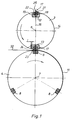
- the cutting device according to the invention is in the Drawing shown and will be described in more detail below described.
- a cutting cylinder 3 and a collecting cylinder 4 are rotatably supported about their parallel axes of rotation 6, 7.
- the collecting cylinder 4 serves as a counter cylinder for the cutting cylinder 3 and is therefore provided with cutting strips 8 fixed to the cylinder.
- Three 120 ° offset cutting strips 8 are congruent with a lateral surface 9 of the collecting cylinder 4 concentric to the axis of rotation 7 of the collecting cylinder 4.
- the collecting cylinder 4 not shown holding devices, for. B. pin needles to hold signatures 11 on.
- the cutting cylinder 3 is an even number, z. B.
- the cutting knife 23, 25 is clamped between the knife receptacles 18, 19 and is laterally by the pressure pieces 21, 22 supported.
- a spacer 24 of thickness d24 which corresponds to length l, is arranged running parallel to the cutting knife carrier 17. This spacer 24 can optionally be included on the right or left in the recess 13.
- the first 23 and second cutting knives 25 are fastened exactly offset by 180 °, which is why the spacer 24 is inserted in the widened part of the recess 13.
- the collecting position of the cutting cylinder 3 results, in which the first cutting knife 23 is offset by the length l parallel to the plane of symmetry 16.
- the two lateral surface sections of the cutting cylinder 3 divided by the cutting knives 23, 25 are of different lengths.
- the cutting cylinder 3 and collecting cylinder 4 are driven by means of a gear located outside the side frame 1.
- a gear 26 of the drive engages in a helical gear 27 of the cutting cylinder 3.
- This gearwheel 27 is connected in a rotationally fixed but axially displaceable manner to a cylinder journal 28 of the cutting cylinder 3.
- This gear 27 meshes with a drive gear 29 of the collecting cylinder 4, which is rigidly connected to the collecting cylinder 4.
- an actuator 31 is provided, which in the present exemplary embodiment is designed as a pneumatic cylinder.
- other actuators 31, in particular also continuously working such as. B. electric motors, linear motors, servo cylinders, etc. are used.
- the cutting device works as follows: In the non-collecting position of the cutting cylinder 3, the two cutting knives 2 are fastened exactly opposite in the cutting cylinder 3. As a result, the cutting cylinder 3 generates signatures of exactly the same length with a length lNS on the collecting cylinder 4. To adjust the cutting cylinder 3 to its collecting position, a first cutting knife 23 is displaced, for example by changing the spacer 24, by an amount l parallel to the plane of symmetry 16, so that the cutting knives 23, 25 are no longer opposite one another, but are offset by this length l.
- the actuator 31 of the gear 27 of the cutting cylinder 3 is actuated, whereby the cutting cylinder 3 is phase-shifted in the circumferential direction by means of the helical gear 27 of the cutting cylinder 3.
- this is achieved by coordinated quantities of the axial offset of the gear 27 and of a helix angle of a toothing of the gear 27.
- a web 32 on the collecting cylinder 4 is cut into signatures with alternating lengths IS1 and IS2.
- the length lS1 of the shorter signatures is shorter by the length l, or the length lS2 of the longer signatures is longer by the length l in the collective mode than the length lNS of the identically long signatures in the non-collective mode.
- This phase shift can change the Cutting register, preferably in a range of 0 be adjustable up to 1/2. This setting can preferably done continuously.
Landscapes
- Life Sciences & Earth Sciences (AREA)
- Forests & Forestry (AREA)
- Engineering & Computer Science (AREA)
- Mechanical Engineering (AREA)
- Folding Of Thin Sheet-Like Materials, Special Discharging Devices, And Others (AREA)
Abstract
Claims (6)
- Dispositif de coupe pour découper transversalement des bandes en mouvement (32), en particulier dans un dispositif de pliage implanté en aval d'une machine à imprimer rotative, comprenant un cylindre de coupe (3) qui comporte un nombre pair de couteaux tranchants (23) et qui est disposé avec la possibilité de coopérer avec un cylindre (4) comportant des barrettes de coupe (8), un premier (23) et un second couteau tranchant (25) étant fixés, dans un premier mode de fonctionnement, au cylindre de coupe (3) de manière diamétralement opposée avec un décalage par paire d'exactement 180°, un premier couteau tranchant (23) étant fixé, dans un second mode de fonctionnement, avec un décalage d'une longueur (l) dans le sens circonférentiel par rapport au second couteau tranchant (25) de chacune des paires de couteaux tranchants, caractérisé en ce qu'un déphasage dans le sens circonférentiel est prévu entre le cylindre de coupe (3) et le cylindre (4) comportant les barrettes de coupe (8).
- Dispositif de coupe selon la revendication 1, caractérisé en ce que ledit déphasage est réglable.
- Dispositif de coupe selon les revendications 1 et 2, caractérisé en ce que le déphasage est compris entre 0 et 1/2 x l.
- Dispositif de coupe selon les revendications 1 et 2, caractérisé en ce qu'une roue dentée à denture hélicoïdale (27) est montée sur le tourillon cylindrique (28) du cylindre de coupe (3) de manière solidaire en rotation et avec une possibilité de translation axiale à l'aide d'un moyen de positionnement (31).
- Dispositif de coupe selon la revendication 1 à 4, caractérisé en ce que le moyen de positionnement (31) prévu est un vérin pneumatique.
- Dispositif de coupe selon la revendication 1, caractérisé en ce que le premier couteau tranchant (23) est disposé avec la possibilité d'être décalé par rapport au second couteau tranchant (25) au moyen d'une pièce d'écartement (24).
Applications Claiming Priority (3)
| Application Number | Priority Date | Filing Date | Title |
|---|---|---|---|
| DE19518661 | 1995-05-20 | ||
| DE19518661 | 1995-05-20 | ||
| PCT/DE1996/000828 WO1996036488A1 (fr) | 1995-05-20 | 1996-05-13 | Dispositif de coupe |
Publications (2)
| Publication Number | Publication Date |
|---|---|
| EP0827454A1 EP0827454A1 (fr) | 1998-03-11 |
| EP0827454B1 true EP0827454B1 (fr) | 1998-11-25 |
Family
ID=7762508
Family Applications (1)
| Application Number | Title | Priority Date | Filing Date |
|---|---|---|---|
| EP96914073A Expired - Lifetime EP0827454B1 (fr) | 1995-05-20 | 1996-05-13 | Dispositif de coupe |
Country Status (5)
| Country | Link |
|---|---|
| US (1) | US5983764A (fr) |
| EP (1) | EP0827454B1 (fr) |
| JP (1) | JP3085984B2 (fr) |
| DE (1) | DE59600877D1 (fr) |
| WO (1) | WO1996036488A1 (fr) |
Families Citing this family (25)
| Publication number | Priority date | Publication date | Assignee | Title |
|---|---|---|---|---|
| GB2332386B (en) * | 1997-12-19 | 2001-08-08 | Bitrim Manufacturers And Distr | A cutting machine |
| US6244151B1 (en) * | 1998-06-11 | 2001-06-12 | Tamarack Products Inc. | Apparatus for adjusting cutting bar |
| DE19953908A1 (de) * | 1999-11-10 | 2001-05-17 | Sms Demag Ag | Hochgeschwindigkeitsschere zum Querteilen von Walzband |
| DE102005002683A1 (de) * | 2005-01-20 | 2006-08-03 | Man Roland Druckmaschinen Ag | Falzapparat für eine Rollenrotationsdruckmaschine |
| US9550306B2 (en) | 2007-02-21 | 2017-01-24 | Curt G. Joa, Inc. | Single transfer insert placement and apparatus with cross-direction insert placement control |
| US9944487B2 (en) | 2007-02-21 | 2018-04-17 | Curt G. Joa, Inc. | Single transfer insert placement method and apparatus |
| US9089453B2 (en) | 2009-12-30 | 2015-07-28 | Curt G. Joa, Inc. | Method for producing absorbent article with stretch film side panel and application of intermittent discrete components of an absorbent article |
| US8656817B2 (en) * | 2011-03-09 | 2014-02-25 | Curt G. Joa | Multi-profile die cutting assembly |
| CA2807809C (fr) | 2012-02-20 | 2019-07-23 | Curt G. Joa, Inc. | Methode de formation de liaisons entre des composants discrets d'articles jetables |
| US9908739B2 (en) | 2012-04-24 | 2018-03-06 | Curt G. Joa, Inc. | Apparatus and method for applying parallel flared elastics to disposable products and disposable products containing parallel flared elastics |
| DE102013102729A1 (de) * | 2013-03-18 | 2014-09-18 | Manroland Web Systems Gmbh | Falzeinrichtung einer Druckmaschine und Verfahren zum Betreiben der Falzeinrichtung |
| US9283683B2 (en) | 2013-07-24 | 2016-03-15 | Curt G. Joa, Inc. | Ventilated vacuum commutation structures |
| USD704237S1 (en) | 2013-08-23 | 2014-05-06 | Curt G. Joa, Inc. | Ventilated vacuum commutation structure |
| USD703247S1 (en) | 2013-08-23 | 2014-04-22 | Curt G. Joa, Inc. | Ventilated vacuum commutation structure |
| USD703712S1 (en) | 2013-08-23 | 2014-04-29 | Curt G. Joa, Inc. | Ventilated vacuum commutation structure |
| USD703248S1 (en) | 2013-08-23 | 2014-04-22 | Curt G. Joa, Inc. | Ventilated vacuum commutation structure |
| USD703711S1 (en) | 2013-08-23 | 2014-04-29 | Curt G. Joa, Inc. | Ventilated vacuum communication structure |
| US9289329B1 (en) | 2013-12-05 | 2016-03-22 | Curt G. Joa, Inc. | Method for producing pant type diapers |
| CA2991328C (fr) | 2015-07-24 | 2021-10-26 | Curt G. Joa, Inc. | Appareil et procedes de commutation a vide |
| US20170341256A1 (en) * | 2016-05-24 | 2017-11-30 | The Procter & Gamble Company | Rotary Anvil |
| US11292016B2 (en) | 2018-03-16 | 2022-04-05 | The Procter & Gamble Company | Nozzle assembly used to manufacture absorbent articles |
| CN111731907B (zh) * | 2019-03-25 | 2022-03-08 | 西门子工厂自动化工程有限公司 | 自动调整横切机切刀角度的方法和横切机 |
| US11737930B2 (en) | 2020-02-27 | 2023-08-29 | Curt G. Joa, Inc. | Configurable single transfer insert placement method and apparatus |
| CN112223380A (zh) * | 2020-10-19 | 2021-01-15 | 东莞理工学院 | 一种口罩机内鼻梁切断结构 |
| CN114770642B (zh) * | 2022-06-20 | 2022-10-11 | 张家港蓝智生物科技有限公司 | 一种抗菌医用敷料制造设备 |
Family Cites Families (8)
| Publication number | Priority date | Publication date | Assignee | Title |
|---|---|---|---|---|
| DE671790C (de) * | 1937-10-10 | 1939-02-14 | Koenig & Bauer Schnellpressfab | Schneid- und Sammelvorrichtung fuer Rotationsdruckmaschinen |
| US4009626A (en) * | 1975-07-09 | 1977-03-01 | Gressman Richard H | Variable rotary cutter |
| JPS6044120B2 (ja) * | 1979-01-08 | 1985-10-01 | 三菱重工業株式会社 | ロ−タリダイカツタ |
| US4467687A (en) * | 1981-12-29 | 1984-08-28 | Special Products Engineering Corporation | Alignment system for a rotary cutter |
| JPH0197887A (ja) * | 1987-10-09 | 1989-04-17 | Furuno Electric Co Ltd | スキャニングソナーの画像表示装置 |
| JPH068717B2 (ja) * | 1987-11-02 | 1994-02-02 | 工業技術院長 | ヒートパイプにおけるウイックの構造 |
| JPH0257876U (fr) * | 1988-10-19 | 1990-04-25 | ||
| DE4244787C2 (de) * | 1992-12-18 | 2000-01-27 | Koenig & Bauer Ag | Einrichtung zum Verschieben von Schneidmesserleisten auf einem Schneidzylinder einer Rotationsdruckmaschine |
-
1996
- 1996-05-13 JP JP08534450A patent/JP3085984B2/ja not_active Expired - Fee Related
- 1996-05-13 EP EP96914073A patent/EP0827454B1/fr not_active Expired - Lifetime
- 1996-05-13 WO PCT/DE1996/000828 patent/WO1996036488A1/fr not_active Ceased
- 1996-05-13 US US08/945,416 patent/US5983764A/en not_active Expired - Fee Related
- 1996-05-13 DE DE59600877T patent/DE59600877D1/de not_active Expired - Fee Related
Also Published As
| Publication number | Publication date |
|---|---|
| DE59600877D1 (de) | 1999-01-07 |
| US5983764A (en) | 1999-11-16 |
| EP0827454A1 (fr) | 1998-03-11 |
| JP3085984B2 (ja) | 2000-09-11 |
| WO1996036488A1 (fr) | 1996-11-21 |
| JPH10506583A (ja) | 1998-06-30 |
Similar Documents
| Publication | Publication Date | Title |
|---|---|---|
| EP0827454B1 (fr) | Dispositif de coupe | |
| EP0557774B1 (fr) | Dispositif pour plier longitudinalement plusieurs bandes de papier de même largeur dans une rotative à bobines | |
| DE3810439C1 (fr) | ||
| DE3828372C2 (de) | Falzapparat | |
| EP0570334B1 (fr) | Cylindre à mâchoires | |
| EP0977668B1 (fr) | Dispositif pour regler des machoires de pliage | |
| DE2652159B2 (de) | Räderfalzapparat | |
| DE3628411A1 (de) | Falzapparat | |
| EP0515945A1 (fr) | Dispositif de pliage | |
| EP0649741B1 (fr) | Dispositif d'accumulation d'un cylindre coupeur-accumulateur d'une plieuse | |
| EP0516649B1 (fr) | Machine rotative d'impression avec appareil de pliage | |
| DE3000321C2 (de) | Rotierende Stanzvorrichtung | |
| EP0938443B1 (fr) | Appareil de pliage | |
| EP0977700B1 (fr) | Procede et dispositif pour le pliage transversal de cahiers d'imprimerie | |
| EP0744368B1 (fr) | Dispositif de coupe | |
| DE19625084C2 (de) | Zylinder | |
| EP0222150B1 (fr) | Plieuse à lames engageantes | |
| EP0639453A1 (fr) | Dispositif pour faire des perforations transversales | |
| EP1918236A2 (fr) | Cylindre de collecte d'un appareil de pliage d'une presse | |
| DE19518652C2 (de) | Vorrichtung zum Heften von Signaturen | |
| DE102005010948A1 (de) | Vorrichtungen zum Trennen von Bahnen | |
| DE2148801A1 (de) | Waelzstossmaschine zur herstellung von zahnraedern oder dgl | |
| EP0827456A1 (fr) | Dispositif de brochage | |
| DE19716625A1 (de) | Einrichtung zum Vorfalzen von Signaturen | |
| DD153473A3 (de) | Vorrichtung zur steuerung der falzklappen eines falzklappenzylinders |
Legal Events
| Date | Code | Title | Description |
|---|---|---|---|
| PUAI | Public reference made under article 153(3) epc to a published international application that has entered the european phase |
Free format text: ORIGINAL CODE: 0009012 |
|
| 17P | Request for examination filed |
Effective date: 19971030 |
|
| AK | Designated contracting states |
Kind code of ref document: A1 Designated state(s): CH DE FR GB IT LI |
|
| GRAG | Despatch of communication of intention to grant |
Free format text: ORIGINAL CODE: EPIDOS AGRA |
|
| GRAG | Despatch of communication of intention to grant |
Free format text: ORIGINAL CODE: EPIDOS AGRA |
|
| GRAH | Despatch of communication of intention to grant a patent |
Free format text: ORIGINAL CODE: EPIDOS IGRA |
|
| 17Q | First examination report despatched |
Effective date: 19980326 |
|
| GRAH | Despatch of communication of intention to grant a patent |
Free format text: ORIGINAL CODE: EPIDOS IGRA |
|
| GRAA | (expected) grant |
Free format text: ORIGINAL CODE: 0009210 |
|
| AK | Designated contracting states |
Kind code of ref document: B1 Designated state(s): CH DE FR GB IT LI |
|
| REG | Reference to a national code |
Ref country code: CH Ref legal event code: EP |
|
| RAP2 | Party data changed (patent owner data changed or rights of a patent transferred) |
Owner name: KOENIG & BAUER AKTIENGESELLSCHAFT |
|
| GBT | Gb: translation of ep patent filed (gb section 77(6)(a)/1977) |
Effective date: 19981126 |
|
| ET | Fr: translation filed | ||
| REF | Corresponds to: |
Ref document number: 59600877 Country of ref document: DE Date of ref document: 19990107 |
|
| PLBE | No opposition filed within time limit |
Free format text: ORIGINAL CODE: 0009261 |
|
| STAA | Information on the status of an ep patent application or granted ep patent |
Free format text: STATUS: NO OPPOSITION FILED WITHIN TIME LIMIT |
|
| 26N | No opposition filed | ||
| REG | Reference to a national code |
Ref country code: GB Ref legal event code: IF02 |
|
| PGFP | Annual fee paid to national office [announced via postgrant information from national office to epo] |
Ref country code: IT Payment date: 20060531 Year of fee payment: 11 |
|
| PGFP | Annual fee paid to national office [announced via postgrant information from national office to epo] |
Ref country code: DE Payment date: 20060626 Year of fee payment: 11 |
|
| PGFP | Annual fee paid to national office [announced via postgrant information from national office to epo] |
Ref country code: CH Payment date: 20070522 Year of fee payment: 12 |
|
| PGFP | Annual fee paid to national office [announced via postgrant information from national office to epo] |
Ref country code: GB Payment date: 20070611 Year of fee payment: 12 |
|
| PG25 | Lapsed in a contracting state [announced via postgrant information from national office to epo] |
Ref country code: DE Free format text: LAPSE BECAUSE OF NON-PAYMENT OF DUE FEES Effective date: 20071201 |
|
| PGFP | Annual fee paid to national office [announced via postgrant information from national office to epo] |
Ref country code: FR Payment date: 20070518 Year of fee payment: 12 |
|
| REG | Reference to a national code |
Ref country code: CH Ref legal event code: PL |
|
| GBPC | Gb: european patent ceased through non-payment of renewal fee |
Effective date: 20080513 |
|
| PG25 | Lapsed in a contracting state [announced via postgrant information from national office to epo] |
Ref country code: LI Free format text: LAPSE BECAUSE OF NON-PAYMENT OF DUE FEES Effective date: 20080531 Ref country code: CH Free format text: LAPSE BECAUSE OF NON-PAYMENT OF DUE FEES Effective date: 20080531 |
|
| REG | Reference to a national code |
Ref country code: FR Ref legal event code: ST Effective date: 20090119 |
|
| PG25 | Lapsed in a contracting state [announced via postgrant information from national office to epo] |
Ref country code: FR Free format text: LAPSE BECAUSE OF NON-PAYMENT OF DUE FEES Effective date: 20080602 |
|
| PG25 | Lapsed in a contracting state [announced via postgrant information from national office to epo] |
Ref country code: GB Free format text: LAPSE BECAUSE OF NON-PAYMENT OF DUE FEES Effective date: 20080513 |
|
| PG25 | Lapsed in a contracting state [announced via postgrant information from national office to epo] |
Ref country code: IT Free format text: LAPSE BECAUSE OF NON-PAYMENT OF DUE FEES Effective date: 20070513 |