EP0827554B1 - Fonctionnement stable d'un haut fourneau - Google Patents
Fonctionnement stable d'un haut fourneau Download PDFInfo
- Publication number
- EP0827554B1 EP0827554B1 EP97916165A EP97916165A EP0827554B1 EP 0827554 B1 EP0827554 B1 EP 0827554B1 EP 97916165 A EP97916165 A EP 97916165A EP 97916165 A EP97916165 A EP 97916165A EP 0827554 B1 EP0827554 B1 EP 0827554B1
- Authority
- EP
- European Patent Office
- Prior art keywords
- slag
- carbon
- approximately
- hydrogen
- range
- Prior art date
- Legal status (The legal status is an assumption and is not a legal conclusion. Google has not performed a legal analysis and makes no representation as to the accuracy of the status listed.)
- Expired - Lifetime
Links
- 239000002893 slag Substances 0.000 claims description 259
- XEEYBQQBJWHFJM-UHFFFAOYSA-N Iron Chemical compound [Fe] XEEYBQQBJWHFJM-UHFFFAOYSA-N 0.000 claims description 194
- UQSXHKLRYXJYBZ-UHFFFAOYSA-N Iron oxide Chemical compound [Fe]=O UQSXHKLRYXJYBZ-UHFFFAOYSA-N 0.000 claims description 189
- 238000000034 method Methods 0.000 claims description 108
- OKTJSMMVPCPJKN-UHFFFAOYSA-N Carbon Chemical compound [C] OKTJSMMVPCPJKN-UHFFFAOYSA-N 0.000 claims description 103
- 229910052799 carbon Inorganic materials 0.000 claims description 102
- 229910052742 iron Inorganic materials 0.000 claims description 98
- 230000008569 process Effects 0.000 claims description 89
- QVGXLLKOCUKJST-UHFFFAOYSA-N atomic oxygen Chemical compound [O] QVGXLLKOCUKJST-UHFFFAOYSA-N 0.000 claims description 88
- 239000003245 coal Substances 0.000 claims description 88
- 239000001301 oxygen Substances 0.000 claims description 88
- 229910052760 oxygen Inorganic materials 0.000 claims description 88
- 238000002485 combustion reaction Methods 0.000 claims description 51
- 239000000571 coke Substances 0.000 claims description 37
- 239000006260 foam Substances 0.000 claims description 37
- 238000006243 chemical reaction Methods 0.000 claims description 34
- 239000001257 hydrogen Substances 0.000 claims description 33
- 229910052739 hydrogen Inorganic materials 0.000 claims description 33
- UFHFLCQGNIYNRP-UHFFFAOYSA-N Hydrogen Chemical compound [H][H] UFHFLCQGNIYNRP-UHFFFAOYSA-N 0.000 claims description 32
- 239000000463 material Substances 0.000 claims description 19
- 238000005187 foaming Methods 0.000 claims description 14
- 238000005259 measurement Methods 0.000 claims description 12
- IJGRMHOSHXDMSA-UHFFFAOYSA-N Atomic nitrogen Chemical compound N#N IJGRMHOSHXDMSA-UHFFFAOYSA-N 0.000 claims description 10
- UGFAIRIUMAVXCW-UHFFFAOYSA-N Carbon monoxide Chemical compound [O+]#[C-] UGFAIRIUMAVXCW-UHFFFAOYSA-N 0.000 claims description 7
- 229910002091 carbon monoxide Inorganic materials 0.000 claims description 7
- 230000004907 flux Effects 0.000 claims description 7
- 229910052757 nitrogen Inorganic materials 0.000 claims description 4
- 150000002431 hydrogen Chemical class 0.000 claims 2
- -1 flux Chemical compound 0.000 claims 1
- 239000011236 particulate material Substances 0.000 claims 1
- 229910052751 metal Inorganic materials 0.000 description 48
- 239000002184 metal Substances 0.000 description 48
- 238000003723 Smelting Methods 0.000 description 43
- 229910052595 hematite Inorganic materials 0.000 description 28
- 239000011019 hematite Substances 0.000 description 28
- LIKBJVNGSGBSGK-UHFFFAOYSA-N iron(3+);oxygen(2-) Chemical compound [O-2].[O-2].[O-2].[Fe+3].[Fe+3] LIKBJVNGSGBSGK-UHFFFAOYSA-N 0.000 description 28
- 239000002245 particle Substances 0.000 description 28
- 229910001868 water Inorganic materials 0.000 description 28
- 239000000428 dust Substances 0.000 description 25
- 239000000446 fuel Substances 0.000 description 24
- 239000007789 gas Substances 0.000 description 19
- 235000013980 iron oxide Nutrition 0.000 description 19
- 230000008859 change Effects 0.000 description 15
- 238000004519 manufacturing process Methods 0.000 description 15
- CURLTUGMZLYLDI-UHFFFAOYSA-N Carbon dioxide Chemical compound O=C=O CURLTUGMZLYLDI-UHFFFAOYSA-N 0.000 description 14
- 230000007423 decrease Effects 0.000 description 10
- 230000000694 effects Effects 0.000 description 10
- 239000000203 mixture Substances 0.000 description 9
- 230000009467 reduction Effects 0.000 description 9
- 239000007787 solid Substances 0.000 description 9
- 239000011449 brick Substances 0.000 description 8
- 239000000523 sample Substances 0.000 description 8
- XLYOFNOQVPJJNP-UHFFFAOYSA-N water Substances O XLYOFNOQVPJJNP-UHFFFAOYSA-N 0.000 description 8
- 239000000126 substance Substances 0.000 description 7
- 238000012546 transfer Methods 0.000 description 6
- NINIDFKCEFEMDL-UHFFFAOYSA-N Sulfur Chemical compound [S] NINIDFKCEFEMDL-UHFFFAOYSA-N 0.000 description 5
- 238000004458 analytical method Methods 0.000 description 5
- 238000007664 blowing Methods 0.000 description 5
- 238000002474 experimental method Methods 0.000 description 5
- 238000004886 process control Methods 0.000 description 5
- 238000003756 stirring Methods 0.000 description 5
- 229910052717 sulfur Inorganic materials 0.000 description 5
- 239000011593 sulfur Substances 0.000 description 5
- 229910000831 Steel Inorganic materials 0.000 description 4
- 238000009529 body temperature measurement Methods 0.000 description 4
- 230000001419 dependent effect Effects 0.000 description 4
- 238000002347 injection Methods 0.000 description 4
- 239000007924 injection Substances 0.000 description 4
- 239000002994 raw material Substances 0.000 description 4
- 239000010959 steel Substances 0.000 description 4
- 230000002411 adverse Effects 0.000 description 3
- 238000009826 distribution Methods 0.000 description 3
- VBMVTYDPPZVILR-UHFFFAOYSA-N iron(2+);oxygen(2-) Chemical class [O-2].[Fe+2] VBMVTYDPPZVILR-UHFFFAOYSA-N 0.000 description 3
- 238000011112 process operation Methods 0.000 description 3
- 239000002699 waste material Substances 0.000 description 3
- 238000004364 calculation method Methods 0.000 description 2
- 238000001816 cooling Methods 0.000 description 2
- 230000003247 decreasing effect Effects 0.000 description 2
- 230000007812 deficiency Effects 0.000 description 2
- 238000013461 design Methods 0.000 description 2
- 229910001873 dinitrogen Inorganic materials 0.000 description 2
- 238000004090 dissolution Methods 0.000 description 2
- 230000020169 heat generation Effects 0.000 description 2
- QMQXDJATSGGYDR-UHFFFAOYSA-N methylidyneiron Chemical compound [C].[Fe] QMQXDJATSGGYDR-UHFFFAOYSA-N 0.000 description 2
- 230000036284 oxygen consumption Effects 0.000 description 2
- 239000008188 pellet Substances 0.000 description 2
- 239000010908 plant waste Substances 0.000 description 2
- 238000011084 recovery Methods 0.000 description 2
- 238000012552 review Methods 0.000 description 2
- OYPRJOBELJOOCE-UHFFFAOYSA-N Calcium Chemical compound [Ca] OYPRJOBELJOOCE-UHFFFAOYSA-N 0.000 description 1
- FYYHWMGAXLPEAU-UHFFFAOYSA-N Magnesium Chemical compound [Mg] FYYHWMGAXLPEAU-UHFFFAOYSA-N 0.000 description 1
- XUIMIQQOPSSXEZ-UHFFFAOYSA-N Silicon Chemical compound [Si] XUIMIQQOPSSXEZ-UHFFFAOYSA-N 0.000 description 1
- 238000010521 absorption reaction Methods 0.000 description 1
- 230000004075 alteration Effects 0.000 description 1
- 229910052782 aluminium Inorganic materials 0.000 description 1
- XAGFODPZIPBFFR-UHFFFAOYSA-N aluminium Chemical compound [Al] XAGFODPZIPBFFR-UHFFFAOYSA-N 0.000 description 1
- 229910052791 calcium Inorganic materials 0.000 description 1
- 239000011575 calcium Substances 0.000 description 1
- 239000003575 carbonaceous material Substances 0.000 description 1
- 230000002301 combined effect Effects 0.000 description 1
- 239000000470 constituent Substances 0.000 description 1
- 239000000498 cooling water Substances 0.000 description 1
- 238000011161 development Methods 0.000 description 1
- 230000009977 dual effect Effects 0.000 description 1
- 238000010891 electric arc Methods 0.000 description 1
- 238000004945 emulsification Methods 0.000 description 1
- 238000005516 engineering process Methods 0.000 description 1
- 238000013213 extrapolation Methods 0.000 description 1
- 238000004868 gas analysis Methods 0.000 description 1
- 238000004817 gas chromatography Methods 0.000 description 1
- 229910002804 graphite Inorganic materials 0.000 description 1
- 239000010439 graphite Substances 0.000 description 1
- 150000002430 hydrocarbons Chemical class 0.000 description 1
- JEIPFZHSYJVQDO-UHFFFAOYSA-N iron(III) oxide Inorganic materials O=[Fe]O[Fe]=O JEIPFZHSYJVQDO-UHFFFAOYSA-N 0.000 description 1
- 230000001788 irregular Effects 0.000 description 1
- 239000007788 liquid Substances 0.000 description 1
- 229910052749 magnesium Inorganic materials 0.000 description 1
- 239000011777 magnesium Substances 0.000 description 1
- 230000007246 mechanism Effects 0.000 description 1
- 150000002739 metals Chemical class 0.000 description 1
- 238000002156 mixing Methods 0.000 description 1
- 238000012544 monitoring process Methods 0.000 description 1
- 230000003287 optical effect Effects 0.000 description 1
- 238000007254 oxidation reaction Methods 0.000 description 1
- 230000035515 penetration Effects 0.000 description 1
- 230000005855 radiation Effects 0.000 description 1
- 238000011946 reduction process Methods 0.000 description 1
- 230000000630 rising effect Effects 0.000 description 1
- 229920006395 saturated elastomer Polymers 0.000 description 1
- 238000013341 scale-up Methods 0.000 description 1
- 229910052710 silicon Inorganic materials 0.000 description 1
- 239000010703 silicon Substances 0.000 description 1
- 239000011343 solid material Substances 0.000 description 1
- 230000006641 stabilisation Effects 0.000 description 1
- 238000011105 stabilization Methods 0.000 description 1
- 230000000087 stabilizing effect Effects 0.000 description 1
- 230000008961 swelling Effects 0.000 description 1
- 238000012360 testing method Methods 0.000 description 1
Images










Classifications
-
- C—CHEMISTRY; METALLURGY
- C21—METALLURGY OF IRON
- C21B—MANUFACTURE OF IRON OR STEEL
- C21B13/00—Making spongy iron or liquid steel, by direct processes
- C21B13/0006—Making spongy iron or liquid steel, by direct processes obtaining iron or steel in a molten state
-
- Y—GENERAL TAGGING OF NEW TECHNOLOGICAL DEVELOPMENTS; GENERAL TAGGING OF CROSS-SECTIONAL TECHNOLOGIES SPANNING OVER SEVERAL SECTIONS OF THE IPC; TECHNICAL SUBJECTS COVERED BY FORMER USPC CROSS-REFERENCE ART COLLECTIONS [XRACs] AND DIGESTS
- Y02—TECHNOLOGIES OR APPLICATIONS FOR MITIGATION OR ADAPTATION AGAINST CLIMATE CHANGE
- Y02P—CLIMATE CHANGE MITIGATION TECHNOLOGIES IN THE PRODUCTION OR PROCESSING OF GOODS
- Y02P10/00—Technologies related to metal processing
- Y02P10/10—Reduction of greenhouse gas [GHG] emissions
- Y02P10/134—Reduction of greenhouse gas [GHG] emissions by avoiding CO2, e.g. using hydrogen
Definitions
- the present invention relates generally to an improved method of producing molten iron. More particularly, the invention concerns a method for stabilizing the operation of a post-combustion smelting process for producing hot, molten iron from iron ores and/or other iron-bearing oxides.
- the material feed rates, the oxygen flow rate, the bottom stirring gas flow rate, the oxygen lance and tuyere configuration, the oxygen lance height, the system pressure, and the slag weight are all examples of variables that generally affect the operating performance of the smelter reactor.
- European Patent Publication No.0418627Al discloses a method of attempting to achieve stable operation of an iron ore smelting reduction process that involves the monitoring of the volume of the slag in the reactor and adjusting one or more of the following process variables to keep the carbon content of the slag between 10% and 200%, based on the weight of the slag: the carbon material supply rate, the oxygen supply rate, and the ore supply rate.
- Prior art process control methods can fail to effectively maintain control of the molten iron temperature and/or the chemical composition of the hot metal produced. Moreover, prior methods of control can cause the slag to foam out of the smelter reactor. It is an object of the present invention to design a method for the stable operation of a smelter reactor that overcomes one or more of those deficiencies of the prior art.
- the present invention relates to a method of producing molten iron in a stable manner in a direct smelting process in which a source of iron oxide, flux, and a source of carbon and hydrogen are charged to a smelter reactor. Oxygen and nitrogen are also charged to the smelter reactor, with at least some of the oxygen being continuously introduced via an overhead lance. Conditions are maintained within the smelter reactor to cause at least some of the iron oxide to be chemically reduced. A bath of molten iron is thus created in the bottom of the smelter reactor, surmounted by a layer of foaming slag. Carbon monoxide is generated within the smelter by the reaction of carbon with iron oxide. The carbon monoxide rises through the slag, as does the hydrogen.
- At least some of the carbon monoxide and hydrogen react within the smelter with the continuously charged oxygen, thereby generating heat for endothermic reactions taking place within the reactor.
- An offgas is released that contains CO, CO 2 , H 2 , and H 2 O.
- At least some of the molten iron produced is removed from the reactor. This is the process, well known in the art, that is improved by the present invention.
- the present invention provides a process of producing molten iron in accordance with claim 1.
- a certain group of conditions is repeatedly measured during the process.
- Those conditions are the slag height, the temperature of the molten iron, the content of CO, CO 2 , H 2 , and H 2 O in the offgas, the carbon content of the molten iron, and the FeO content (weight percent) in the slag.
- One or more process variables are subsequently adjusted (after the measurements) so as to help keep one or more of those conditions (slag height, etc.) within a predetermined range.
- the process variable or variables that are adjusted are selected from the group consisting of the addition rate of the carbon and hydrogen source, the addition rate of the source of iron oxide, the addition rate of flux, the addition rate of oxygen, the height of the oxygen lance relative to the slag, the rate at which the bath of molten iron is stirred, and the rate at which molten iron and slag are removed from the smelter reactor.
- the present method enables one to create a stable iron smelting process that maximizes the molten iron production rate, while minimizing the fuel and oxygen consumption rates.
- slag height is meant the level in the reactor where the upper surface of the slag layer is. Suitable methods of measuring slag height are known in the art. For example, slag height can be measured by an acoustic technique or by using a conductivity probe. If the slag height is not measured continuously, then it preferably is measured at least as often as once every 30 minutes.
- thermocouple device or an optical pyrometer can be used. If the temperature of the molten iron is not continuously monitored, then it, too, is preferably measured at least as often as once every 30 minutes.
- Means of measuring the content of CO, CO 2 , H 2 , and H 2 O in the offgas are also known in the art.
- a mass spectrometer or gas chromatography equipment can be used. If the offgas's content of each of these four chemicals is not continuously measured, then it is preferred that they be measured at least once every 15 minutes.
- Means of measuring the carbon content of the molten iron are likewise known in the art. For example, a sample of hot metal can be taken using a sub-lance, and that sample can then be analyzed using infra-red absorption techniques. If the carbon content of the molten iron is not continuously measured, then preferably it is measured at least as frequently as once every 30 minutes.
- Methods of measuring the FeO content of the slag during the smelting reduction of iron oxide are likewise known in the art.
- a sample of the slag can be taken using a sub-lance, and that sample can be analyzed using an x-ray spectrophotometer. If the FeO content of the slag is not continuously measured, then preferably it will be measured at least as frequently as once every 30 minutes.
- the slag height is kept more than one meter below the cone of the smelter reactor. (By the "cone” is meant the topmost portion of the reactor, where the walls slant inwardly. In the reactor shown in Figure 2 of the drawings accompanying this specification, the cone is the "Gun/Cooled” section.)
- the temperature of the molten iron is preferably maintained within the range of approximately 1450°C to approximately 1550°C during operation.
- the carbon content of the molten iron preferably falls within the range of approximately 4% to approximately 4.5% (weight basis).
- it is preferable to have a FeO content in the slag within the range of approximately 2% to approximately 5% (weight basis).
- PCD 100 x (%CO 2 +%H 2 O) (%CO+%CO 2 +%H 2 +%H 2 O)
- the PCD is maintained within the range of approximately 30% to approximately 60%. If the majority (dry weight basis) of the carbonaceous fuel is coal, the PCD will preferably be kept within the range of about 30% to about 50% (e.g., about 30% to about 40%). If the majority of the fuel is coke, the PCD preferably will be kept with the range of about 45% to about 60% (e.g., about 50% to about 60%).
- the measured process conditions are used as a feedback control to regulate one or more of the variables of the process.
- the way or ways in which a change in each of the aforementioned process variables will tend to affect one or more of the measured process conditions will now be discussed.
- slag height can be altered.
- addition rate of oxygen to the smelter reactor By adjusting the addition rate of oxygen to the smelter reactor, the hot metal temperature, slag height, and slag FeO content can be altered.
- the PCD and hot metal temperature can be altered.
- the bath of molten iron can be stirred by the injection of nitrogen using tuyeres installed at the bottom of the smelter reactor.
- the rate at which the bath of molten iron is stirred the PCD, hot metal carbon content, and hot metal temperature can be altered.
- the PCD, slag height, and slag FeO content can be altered.
- Figure 1 illustrates a smelter reactor 1, used for the production of molten iron 3.
- the smelter reactor 1 can be any of a number of types of smelter reactors commonly known to those skilled in the art and used for the smelting of metals and their ores.
- Figure 2 shows one example of a smelter reactor 1 used in the generation of molten iron bath 3.
- the smelter reactor 1 has a brick/cooled section A and a brick/insulated section B in which the process of the invention is to occur.
- the smelter reactor 1 has a water-cooled cone and hood 5 at the top of the smelter reactor 1.
- the smelter reactor 1 is lined with a refractory brick 7 up to the cone 5 of the smelter reactor 1.
- the refractory brick 7 located above the molten iron bath 3 is backed by water-cooled staves 9.
- the refractory brick 7 located below the molten iron bath 3 is backed by an insulating safety lining 11. Both the cone and hood 5 are water cooled by staves 9 as well.
- Smelter reactor 1 contains a taphole 13, where molten iron 3 or slag 15 is removed.
- a source of iron oxide 17, such as iron ore, is being reduced to iron and the resulting iron is being refined.
- a molten iron bath 3 is formed in the bottom of smelter reactor 1.
- a molten, foamy layer of slag 15 surmounts the iron bath 3.
- the slag 15 consists of a dense slag region ⁇ , and foamed slag region ⁇ .
- the dense slag region ⁇ has molten iron droplets 19 dispersed throughout.
- the iron droplets 19 are formed by emulsification of the iron bath 3 by the addition of nitrogen gas 21 and oxygen 23 to the smelter reactor 1 and by the reduction of iron oxide.
- the nitrogen gas 21 is introduced to the bottom of the smelter reactor 1 through tuyeres (not shown).
- the introduction of nitrogen 21 aids the stirring and mixing of molten iron 3 in smelter reactor 1.
- oxygen 23 is continuously top blown via a central, water-cooled, dual circuit lance (not shown) into the slag 15.
- U.S. Patent No. 5,374,297 discloses a suitable structure of an overhead lance for injecting oxygen 23.
- foaming slag region ⁇ has some quantity of molten iron droplets 19 dispersed throughout, but not to the extent of the ⁇ region.
- a carbon and hydrogen source 25 is charged to the smelter reactor 1 to produce char particles 27 that are dispersed throughout the foaming region ⁇ of slag 15.
- the aggregate of all the char particles 27 in slag 15 make up total char 28.
- the carbon and hydrogen source 25 consists of one or more of the following: coke breeze, low volatile coal, medium volatile coal, and high volatile coal.
- Some of the carbon typically will be in elemental form, which is referred to herein as "fixed carbon.”
- the rest of the carbon will be present in the carbon source as hydrocarbon compounds that volatize at the temperatures inside the reactor. That portion may be referred to herein as "volatile matter carbon.”
- the carbon and hydrogen source material 25 is advantageously top charged via the same overhead lance used to introduce oxygen 23.
- a flux 29 is charged to the smelter reactor 1, e.g., also by way of an overhead lance (not shown).
- the iron oxides 17 charged to the smelter reactor 1 dissolve in the layer of slag 15 and are reduced by char 28 and carbon contained within iron droplets 19 present in the slag 15.
- Gangue components of the carbon source 25 and the iron oxide source 17 report to the layer of slag 15. Examples of such gangue components are oxides of calcium, silicon, magnesium, aluminum, etc.
- certain feeds may contain high levels of sulfur, as described in the U.S. Patent No. 5,980,606 entitled "Method for Reducing Sulfur Levels in the Offgas of an Iron Smelting Process Utilizing Post Combustion" by Sarma et al.
- the bath of molten iron 3 and the layer of slag 15 that are produced are tapped, to remove some of each respective layer from the smelter 1.
- the smelter reactor 1 is tapped at a single taphole 13 using a mudgun and drill system (not shown).
- the removed molten iron 3 is carbon saturated hot metal 4 that can be further pigged/granulated, or used in a basic oxygen furnace or electric arc furnace for the production of steel.
- the combined effect of the devolatilization of the carbon and hydrogen source 25, the combustion of fixed carbon and volatile matter, and the reduction of iron oxide 17 is the evolution of gases which cause at least part of the layer of slag 15 to foam.
- this gas is CO, which is produced by the primary combustion of fixed carbon and volatile matter carbon.
- the CO present within the foamy layer ⁇ of slag 15 subsequently rises to the surface of slag 15. At least some of the CO reacts with the continuously charged oxygen 23 and hydrogen present within smelter reactor 1.
- the rising gases also cause at least some of the slag 15 to be thrown up into the free space of the smelter reactor 1, which is referred to as slag splatter.
- the slag 15 also contains char 28 that remains after the carbon source 25 has devolatized.
- the slag 15 is crucial to the smelting process since it is the medium where reduction and heat transfer occur.
- slag 15 separates the hot iron bath 3 from the continuously blown oxygen 23, preventing re-oxidation of the iron.
- the thermal requirements of the process are provided by the heat generated during a primary combustion reaction and a post-combustion reaction.
- the primary reaction fixed carbon and volatile matter react with the continuously blown oxygen 23 to produce CO.
- the post-combustion reaction the CO and H 2 react with the top-blown oxygen 23 to produce CO 2 and H 2 O.
- the heat generated from those reactions is transferred to the incoming raw material stream, to the slag 15 via radiation and convection, to the iron droplets 19, and to the char 28 present in the slag 15. Heat is also transferred to the refractory bricks 7 and the water-cooled staves 9.
- the remainder of the heat generated is contained within the offgas 31 exiting the smelter reactor 1.
- the offgas 31 contains a plurality of constituents, including CO, CO 2 , H 2 , and H 2 O.
- the interrelationships between various process parameters are governed by these process phenomena. Applicants have conducted numerous experiments in order to understand the process phenomena necessary for an effective process control scheme.
- various conditions are repeatedly measured to ensure an effective process control scheme.
- the content of CO, CO 2 , H 2 , and H 2 O in the offgas 31, the post-combustion degree, the FeO % content of slag 15, the carbon content of hot metal 4, the slag height, the temperature of hot metal 4, the heat losses to the water-cooled circuits, and the temperature of offgas 31 are all measured.
- Additional process parameters are advantageously measured, including the material feedrates, gas flowrates, system pressure, lance height, and the amount of slag 15 and iron 3 tapped from the smelter 1.
- the offgas 31 composition was analyzed using multiple Perkin-Elmer mass spectrometers. The contents of CO, CO 2 , H 2 , H 2 O, N 2 , and Ar were measured in the offgas 31 every four seconds.
- the FeO content of the slag and the carbon content of hot metal 4 were obtained from the chemical analysis of samples taken using a sub-lance (not shown).
- the temperature of the molten iron 3 was also measured using the sub-lance.
- the slag foam height was measured either by a conductivity probe or by a chain attached to the sub-lance. These measurements were intermittent and obtained only when the relevant probes were attached to the sub-lance.
- the heat losses to the water-cooled portions of the smelter reactor 1 were obtained by measuring the flowrate, inlet temperature, and exit temperature of water passing through staves 9.
- the temperature of offgas 31 in the exit duct was measured by a thermocouple.
- the weight of slag 15 was calculated from a mass balance by taking into account the gangue components of the input materials and the amount of tapped slag 15.
- the main process variables are the material feed rates, oxygen flow rate, bottom stirring gas flow rate, oxygen lance and tuyere configuration, lance height, system pressure, and slag weight.
- a change in the rate of input of solid material or gas to the smelter can be made in a very short time.
- one or more process variables are subsequently adjusted so as to keep one or more process conditions within a predetermined range.
- the configuration of the oxygen lance and tuyere are fixed during operation.
- the position of the oxygen lance in relation to the slag 15 can be altered during the smelting operation.
- U.S. Patent No. 5,885,322 by Sarma et al. entitled “Method For Reducing Iron Losses in an Iron Smelting Process” discloses a method of altering the position of the lance to reduce iron losses.
- the system pressure is normally fixed at the maximum possible, since this generally results in better operating performance.
- the prime process variables subject to alteration between casts are the material feedrates of carbon, hydrogen, and iron oxide sources, the flowrate of O 2 , the flowrate of N 2 , and the lance height.
- the reduction kinetics in the smelter reactor 1 govern the relationship between the FeO % content of the slag 15, the feedrate of iron oxide 17, the weight of slag 15, the weight of char 28, the size distribution of char particles 27, the iron droplet 19 weight, and the size distribution of iron droplets 19.
- the overall production of iron 3 results from chemical reactions between the FeO in the slag 15 and (a) char particles 27 in the slag 15, (b) carbon containing iron droplets 19 in the slag 15, and (c) carbon contained within the iron bath 3.
- R total is related to the feedrate of the iron-bearing materials 17. With others parameters being held constant, a higher feedrate of iron-bearing materials 17 to the smelter 1 will result in higher slag FeO% content.
- the rate coefficient for the slag-metal reactions, k 1 includes the interfacial area between the iron droplets 19 and slag 15, as well as the interfacial area between the iron bath 3 and the slag 15.
- the interfacial area between the iron droplets 19 and slag 15 is dependent on the size distribution of the droplets 19 in the slag 15.
- the interfacial area may be represented by (i) an average droplet diameter and (ii) the weight ratio of metal droplets 19 to slag 15. With other parameters being constant, a larger average droplet diameter results in a higher slag FeO% content. Conversely, an increased droplet-to-slag weight ratio results in lower slag FeO% levels.
- the mathematical representation of the rate coefficient for the slag-char reaction, k 2 is similar to that for the slag-metal reactions.
- the interfacial area for the slag-char reactions may be represented by an average char particle 27 diameter, and the weight ratio of char 28 to slag 15. With other parameters being constant, a larger char particle 27 diameter results in higher slag FeO% content. Conversely, a higher char-to-slag weight ratio results in lower slag FeO% levels. From equation (2), it can also be deduced that a higher weight of slag 15 results in lower slag FeO% levels, with other parameters remaining constant.
- the reaction between smelting slag 15 and iron-carbon droplets 19 was studied.
- the reaction rate was found to be affected by the sulfur content in the droplet 19.
- the surface active nature of sulfur it was concluded, results in the reaction being controlled by chemical kinetics at high sulfur levels. From the experimental work, the rate constant for the slag-metal reactions is estimated to be approximately 4 x 10 -4 tonnes/(h m 2 %FeO).
- the reaction between smelting slag 15 and solid carbon was studied. Experiments were conducted with graphite, coke, and coal char. The reaction rate was experimentally determined to be independent of the form of carbon used. Moreover, the reaction rate was found to be mass-transfer controlled. The reaction rate was discovered to be proportional to (%FeO) n , where n is slightly greater than 1. Experimentally, the rate constant for the slag-char reaction, k 2 , was estimated and the non-linear dependence on (%FeO) was taken into account.
- the rate coefficients k 1 and k 2 could be estimated.
- the average diameter of the metal droplets 19 in the slag 15 was estimated to be approximately 1 mm, while the droplet-to-slag weight ratio was estimated to be 0.1.
- the char-to-slag weight ratio calculated from the material balances ranged from 0.15 to 0.35 during normal smelter operation.
- the range of values for the char-to-slag weight ratio were used in equation (2).
- the range of values for the average char particle 27 diameter was taken to be 3 to 6 mm when using equation (2).
- Figure 3 shows the relationship between the oxygen removal rate, expressed in kmol O 2 /min, and the FeO% content of slag 15 for data obtained during pilot plant operations. These data are for situations when the weight of slag 15 was in a narrow range of around 4 to 5 tonnes.
- the filled circles represent the data obtained at the pilot plant, while the solid lines represent the calculated relationship.
- the oxygen removal rate from the iron ore is equivalent to the production rate of iron 3 and is determined from the feedrate of the iron-bearing oxides 17.
- the scatter in the data is caused by variations in the weight of slag 15, average char particle 27 size, char-to-slag weight ratio, size of iron droplets 19, and the droplet-to-slag weight ratio.
- the solid lines were calculated using the rate equation discussed above and the following parameters.
- the average char particle 27 diameter was taken to be 6 mm and the average diameter of iron droplet 19 was taken to be 1 mm.
- the droplet-to-slag weight ratio was taken to be 0.1.
- the lower solid line was calculated for a char-to-slag weight ratio of 0.15 and a slag weight of 4 tonnes.
- the upper solid line was calculated for a char-to-slag weight ratio of 0.35 and a slag weight of 5 tonnes.
- the oxygen removal rate increases at higher slag FeO% levels.
- equation (2) it can be seen that the slope of the oxygen removal rate versus the FeO% content of the slag 15, at constant slag weight, should be positive. This is indicated by the data, wherein the slope is dependent on the char-to-slag weight ratio, the size of char particles 27, the droplet-to-slag weight ratio, and the size of iron droplets 19. It is worthwhile to review the two extreme situations which are represented by data points lying outside the solid lines. For the datum point at about 9% FeO, observation into the smelter reactor 1 at turndown indicated that not much char 28 was present. For the datum point at about 3% FeO, the higher oxygen removal rate was a result of substantial char 28 present at turndown.
- the oxygen removal rate per unit slag FeO% is plotted against weight of slag 15 in Figure 4. Pilot plant data obtained during operation with top-charged coarse coal as well as top-charged coarse coal and injected fine coal are shown. (Note that top-charged coal or coarse coal also includes coke breeze.) The increase in the removal rate of oxygen 23 per unit slag FeO% at higher slag weight is evident. This trend is also predicted by equation (2) and the slope of the plot is dependent on the parameters affecting k 1 and k 2 , namely the size of droplets 19, the droplet-to-slag weight ratio, the char particle 27 size, and the char-to-slag weight ratio.
- the relationship between the oxygen removal rate per unit weight of slag 15 and the slag FeO% content is illustrated in Figure 5.
- a comparison between the data for operation with coarse coal and that for a mix of coarse and fine coal is also depicted.
- the data presented in this figure encompass a weight of slag 15 in the range of about 1.5 to 8 tonnes.
- the solid lines were calculated for an average diameter of droplet 19 of around 1 mm and a droplet-to-slag weight ratio of 0.1.
- the lower solid line assumes an average diameter of char particle 27 of around 6 mm and a char-to-slag weight ratio of 0.15.
- the upper solid line is for a char diameter of 3 mm and a char-to-slag weight ratio of 0.35.
- the amount of char 28 present in the slag 15 is believed to be an important parameter in the smelting process.
- the weight of char 28 affects the slag FeO% content, post-combustion degree, and slag foaming.
- the weight of char 28 is not a directly measurable quantity and must be calculated from the carbon balance.
- errors in the carbon balance can be caused by problems with the analysis of the offgas 31.
- incorrect estimation of carbon dust leaving the smelter 1 and incorrect coal feedrate measurements can skew the carbon balance.
- the amount of char 28 present in the slag 15 can be inferred if the FeO% content of the slag 15 and the weight of slag 15 are known. This can be done by using established relationships between the oxygen removal rate per unit of slag weight and the slag FeO% content as shown in Figure 5.
- the information presented in Figure 5 can also be used when designing a scaled-up smelter reactor 1.
- the weight of slag 15 is one of the parameters that determine the required smelter reactor volume.
- the required weight of slag 15 can be calculated as follows.
- Figure 5 shows an oxygen removal rate per unit of slag weight of approximately 0.15 kmol O 2 /(min x t-slag).
- the required weight of slag 15 is then calculated to be around 40 tonnes.
- a central feature of this process is the partial afterburning of the offgas 31 and the subsequent heat recovery within the smelter 1.
- the afterburning of the offgas 31 is referred to as post-combustion or secondary combustion, with the post-combustion degree being represented by equation 1.
- the post-combustion degree (PCD) of the offgas 31 is affected by the amount of char 28 in the slag 15, the lance gap, the lance configuration, the bottom stirring gas flowrate, the system pressure, and the volatile matter input.
- the lance gap is defined as the distance between the tip of the lance (the lowermost oxygen outlet) and the upper surface of slag layer 15.
- the PCD varies directly with the lance gap and system pressure, while it is inversely related to the char weight, bottom stirring gas flowrate, and the volatile matter input.
- Figure 6 shows the effect of volatile matter input on the PCD.
- increasing the volatile matter input to the smelter 1 results in a lower offgas PCD.
- the solid line represents the calculated offgas PCD if 44% of the gaseous oxygen 23 input to the smelter 1 is used for post-combustion.
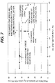
- the fraction of gaseous oxygen 23 used for post-combustion is lower, as can be seen in Figure 7.
- the fraction of gaseous oxygen 23 used for post-combustion is almost 50% when a portion of the oxygen 23 is injected through side tuyeres.
- the scatter in the data for operation with top-charged medium volatile coal is caused by variations in the lance gap and weight of char 28.
- the oxygen blowing rate was usually around 5500 Nm 3 /h.
- the amount of oxygen 23 available for post-combustion is determined by the amount of oxygen used for combustion of fixed carbon.
- the fixed carbon content of coal decreases with increasing volatile matter content.
- the carbon and hydrogen content of the volatile matter must be effectively burnt, such that the fixed carbon consumption decreases.
- Figure 8 illustrates the relationship between the fixed carbon used for combustion and the volatile matter input.
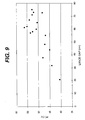
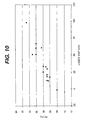
- the lance gap also affects the offgas PCD.
- the lance height is continuously recorded while the slag height is measured intermittently, using a probe attached to the sub-lance (not shown).
- 'A positive lance gap means that the surface of the slag 15 is below the lance tip.
- Figure 9 shows the data for operation with top-charged coke breeze
- Figure 10 shows the data for operation with top-charged medium volatile coal. From Figure 9 it can be seen that to obtain offgas PCD levels in excess of 50%, the lance gap must be greater than about 55 cm. With medium volatile coal, in order to obtain PCD levels in excess of 35%, the lance gap must be greater than about 50 cm. This information is important for operating purposes, since it can be used to infer the weight of char 28 in the smelter 1.
- the lower PCD may be attributed to excess char 28 present in the smelter 1.
- Lowering the carbon-to-iron ore ratio input to smelter 1 can then decrease the required amount of char 28 and return the PCD to the preferred range. The effect of the weight of char 28 on the PCD is discussed in the following paragraphs.
- the relationship between the weight of char 28 and the offgas PCD is based on the reaction between CO 2 and H 2 O with char particles 27. The extent to which these reactions occur between the offgas 31 and char 28 plays an important role in determining the final PCD of the offgas 31.
- the reactions, which result in the production of CO and H 2 are shown below: CO 2(g) + C (s) ⁇ 2 CO (g) H 2 O (g) + C (s) ⁇ H 2(g) + CO (g)
- the relationship between the change in the offgas PCD as a function of the excess weight of char 28 can be derived using the individual rate equations for reactions (3) and (4).
- the excess char weight of char 28 is related to the excess interfacial area for the gas-char reactions through the average diameter of char particles 27.
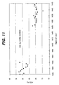
- Figure 11 shows the results of an experiment conducted to establish the effect of weight of char 28 on the offgas PCD.
- a medium volatile coal at about 30% PCD
- about 950 kg of coke breeze was added over a 30 minute period.
- Both the height and temperature of slag 15 were measured prior to the addition of coke breeze.
- the height of slag 15, as well as the slag temperature were again measured.
- the lance was then repositioned such that the lance gap was the same as that prior to the coke addition.
- the offgas PCD decreased to about 20%, which was about 10% lower than that prior to the coke addition. Accordingly, in this experiment it was observed that the offgas PCD change was about 1% for 100 kg of excess char. This observation was confirmed in subsequent pilot plant trials and the relationship between the change in the offgas PCD and the change in weight of char 28 is shown in Figure 12.
- the configuration of the central lance tip also has an effect on the offgas PCD levels.
- the lance has two separate oxygen circuits, i.e., a primary circuit and a secondary circuit.
- the primary circuits have approximately 3 to 4 nozzles, with an exit angle of approximately 10° to 15° from the vertical axis.
- the secondary circuits preferably have approximately 6 to 8 nozzles, with exit angles being in the range of approximately 30° to 45°.
- the primary oxygen jets were operating in the sonic or supersonic range, while the secondary oxygen jets were operating in subsonic range.
- the oxygen lance used had four primary nozzles (10° straight bore) and eight secondary nozzles (4@32° and 4@36°). The primary and secondary nozzles were at the same elevation in all lances except one. This lance was termed the "step lance," wherein the secondary nozzles were 60 cm above the primary nozzles.
- the lance selected for continued use was designed for an oxygen flowrate of around 5500 Nm 3 /h.
- the velocity of the primary oxygen jets, at a furnace pressure of approximately 0.7 kg/cm 2 gauge and a flowrate of 2450 Nm 3 /h, was estimated to be around Mach 1.15.
- the information relevant to the offgas post-combustion degree may be used in the following manner to maintain stable operation of the smelter 1.
- the velocity of the primary oxygen jets is preferably in the sonic range, while that of the secondary jets is preferably subsonic.
- the offgas PCD obtainable can be quantified based on the volatile matter input, the char-to-slag weight ratio, and the lance gap.
- the lance can be repositioned in the range required for the desired PCD.
- the weight of char 28 in the slag 15 can be changed by altering the coal-to-iron input ratio. The excess or deficiency of char 28 can be confirmed by the slag FeO% content prior to making the change in the material feedrates.
- the foaming slag 15 has important implications in the smelting process. Foaming plays a role in determining the required smelter reactor volume for a desired production rate of hot metal 4. Also, it is desirable to maintain a stable foam height, since it affects the post-combustion degree and rate of heat transfer. In addition, operation of the smelter reactor 1 can be temporarily interrupted if the slag 15 foams out of the smelter reactor 1 and into the offgas ducts.
- the volume of slag foam was found to be proportional to the volumetric offgas flow rate. Alterna- tively, this may be stated as the height of the foamed slag being proportional to the superficial gas velocity.
- the foaming phenomenon is represented by the foam index, which is a measure of the travel time of the gas through the slag 15. More specifically, the foam index is defined as the ratio of the foam height to the superficial gas velocity.
- the foam index has units of time (seconds) and was found to be directly proportional to the viscosity, inversely proportional to the surface tension, and inversely proportional to slag density and bubble diameter.
- FIG. 13 shows the relationship between the foam index and the lance gap. As can be seen in Figure 13, at higher lance gaps, the foam index decreases. This implies that with other conditions being held constant, a lower lance gap results in a higher foam height. This effect can be attributed to additional gas passing through the slag 15 at lower lance gaps.
- the relationship between the offgas flow rate and the foam volume is shown in Figure 14 under stable operating conditions.
- the solid line represents the predicted relationship for a foam index of 0.5 seconds. With proper operating conditions, such as adequate lance gap and char weight, the foam index can be controlled to below 0.5 seconds.
- the size of the char particles 27 was found to be an important factor in controlling the slag foam.
- the top-charged coal size used in the smelter was "Stoker Coal". More than 80% (by weight) of the top-charged coal was finer than 1 inch in average diameter, while less than 10% of the coal was finer than 3.175mm (1/8 inch) in average diameter.
- fine coal was injected into the slag 15 through side tuyeres.
- the injected coal rate was varied with up to 63% (by weight) of the total fuel amount being injected.
- the injected coal was 100% finer than 2 mm and 50% finer than 0.35 mm.
- the slag 15 did not foam out of the smelter reactor 1 when adequate char 28 was present in the slag 15.
- the fine coal injection rate was increased to 63% of the total fuel, slopping occurred. This was not due to the lack of char 28 in the slag 15, since the carbon balances showed that the total fuel supply was adequate to maintain the normal amount of char 28.
- char particles 27 was a factor in controlling the slag foam.
- the optimum size of char particles 27 can be achieved by charging coarse coal, e.g., "Stoker Coal” that has an average diameter in the range of about 3.175mm (1/8 inch) to about 25.4mm (1 inch). This may result, for example, in an average diameter char size of approximately 6 mm. Fine coal which is 100% finer than 2 mm can, however, be injected, but preferably this will not exceed about 40% of the total fuel input.
- the particle diameter will preferably be approximately 6 mm, which can be obtained by using "Pea Coke".
- the foam index can be taken to be 0.5 seconds for determining the required volume of smelter reactor 1.
- a volume is estimated that allows for additional volume in the event of process deviations.
- the lance tip is preferably kept at least above the slag surface, such that the foam index is below 0.5 seconds.
- the fuel charged to the smelter be such as to result in the average diameter of the char particles 27 being somewhere in the range of about 3 to 9 mm, most preferably about 5 to 7 mm.
- heat generated in the smelter reactor 1 is recovered by heat transfer to the raw material stream, to the slag 15, to the char 28, and to spatter and iron droplets 19.
- the thermal efficiency in the smelter reactor 1 is dependent on the lance gap, weight of char 28, and blowing practice. Since the thermal efficiency is not a directly measurable quantity, indicators are used to infer the extent of heat recovery. These indicators include the heat losses to the water-cooled regions of the smelter 1, the rate of temperature rise in the thermocouples installed in the refractory bricks 7, the temperature of offgas 31 in the duct, the temperature of hot metal 4, and the thermal efficiency calculated from the heat balance of the process.
- the main objective of the control scheme is to maintain stable process operation, while obtaining the maximum possible production rate of hot metal 4 at the minimum possible fuel and oxygen rates.
- stable operation refers to substantially consistent PCD, slag FeO content, temperature of hot metal 4, carbon content of hot metal 4, and slag height, such that the slag 15 does not overflow from the smelter reactor and disrupt operation.
- the oxygen blowing rate is typically fixed. Material is charged to the smelter 1 in such a manner that the temperature of hot metal 4 is maintained with the desired range.
- the energy balance of the process determines the total solid input for a given oxygen blowing rate.
- the individual coal and ore feedrates are based on the offgas post-combustion degree and the carbon balance.
- neither the energy generated nor the weight of char 28 in the slag 15 is a directly measurable parameter.
- the state of the process with regard to the energy and materials balance can be deduced.
- the PCD is obtained from the analysis of offgas 31. If the offgas analysis system fails or is working improperly, inaccurate estimations of the quantity of heat generated are produced. Consequently, there can be a loss of temperature control. However, if temperature measurements of hot metal 4 are available on a regular basis, these measurements can be combined with the energy balance to deduce the offgas PCD. Accordingly, a stable process operation can be maintained. Similarly, if the raw material feedrates are not accurately measured, then the total solid input to the smelter will adversely affect the quantity for heat generated. This has the potential to adversely affect the temperature of hot metal 4. However, if the temperature measurements of hot metal 4 using the sub-lance are regularly obtained, the error in the measurements in the total solid input to the smelter 1 can be deduced and appropriate changes can be made.
- Deviations in the slag foam height from that desired can occur due to problems with the carbon balance or inadequate control of the amount of slag 15 tapped from the smelter 1. Further errors in the carbon balance can also result if the carbon content in hot metal 4 is below that desired. Errors in the carbon balance can also arise due to incorrect estimation of parameters used in the materials balance, such as the amount of carbon dust, the carbon content in the raw materials, or inaccurate measurement of the material feedrates. Such errors can result in a loss of slag foam control and/or hot metal carbon content control.
- the carbon balance can not be closed, thereby affecting the amount of char 28 in the slag 15.
- foam height measurements, slag FeO% measurements, and hot metal temperature measurements are available on a regular basis, it is believed to be possible to deduce the PCD and maintain a stable process operation.
- the amount of carbon dust is higher than that used in the materials balances, then a decrease in the weight of char 28 will occur. This can be determined from the higher slag FeO% and higher foam height. Appropriate changes to the fuel rate can then be made to return the process to a stable operating mode.
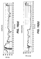
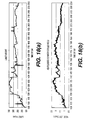
- Figures 15 through 18 represent operating parameters from a pilot plant trial with top-charged medium volatile coal as the fuel. Hematite pellets and agglomerated steel plant waste oxides were used as the iron-bearing feed 17 in this trial. Type D2 agglomerate waste oxides were charged to the smelters. Further, blast furnace dust was injected into the slag 15. Table 1, below, shows the chemical composition of agglomerate D2 and blast furnace dust.
- Figures 15(a) through 15(d) show the offgas post-combustion degree, the total solid input, the total heat losses to the cooling water circuits, and the measured sub-lance temperature.
- the temperature of hot metal 4 was below the target range of 1500°C to 1550°C.
- temperature control of hot metal 4 was much easier and the degree of control is demonstrated by the measurements.
- the lance height, as well as the heat losses to the individual water cooling circuits, are shown in Figures 18(a) through 18(d).
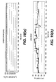
- Figures 19 and 20 illustrate operating parameters during a pilot plant trial with top-charged coke breeze as the fuel source.
- Hematite pellets and agglomerated steel plant waste oxides were used as the iron bearing feed 17 in this trial.
- Type C agglomerate waste oxides were charged to the smelter 1.
- Table 1, above, shows the chemical composition of agglomerate C.
- the oxygen flowrate, lance height, offgas post-combustion degree, and fuel rate are shown in Figures 19(a) through 19(d).
- the offgas PCD was above 50% for most of the trial, except for a brief period following the fourth cast. During this cast, about 7.3 tonnes of slag was cast, which is almost twice the normal amount.
- the temperature of hot metal 4 can be seen to decrease after the addition of agglomerated waste oxides began. After a few sub-lance temperature measurements were taken, the deviation corrected, which resulted in the stabilization of the temperature at the new level.
- the increase in the temperature of hot metal 4 after the fourth cast was a result of a change in the energy balance due to the variations in the PCD. Compensation of solid input to the smelter 1 lagged by a short time period, resulting in the temperature of hot metal 4 taking a little longer to stabilize.
- Example mean residence time calculations were conducted for operations with top-charged low volatile coal and hematite ore.
- the coal input was 7850 kg/h, while the ore feedrate was 9246 kg/h.
- the PCD was taken to be around 35%.
- the mean residence times calculated for FeO, carbon, and the offgas 31 in the smelter reactor 1 are discussed below.
- the FeO input to the smelter 1 is calculated assuming the iron ore contains 87.48% Fe 2 O 3 and 5% H 2 O. Assuming FeO losses of around 5% of the total input, the amount of FeO actually entering the smelter reactor can be calculated to be 6761 kg/h. For a slag weight of 7 tons, containing 5% FeO, the amount of FeO present in the smelter reactor 1 is 350 kg. If this amount of FeO is to be maintained, the mean residence time is be calculated to be 3.1 minutes. The mean residence time varies directly with the weight of slag 15 and FeO content, and varies inversely with the amount of FeO lost as dust. For example, if there were no FeO losses, then the mean residence time is 2.95 minutes. Clearly, the mean residence time of FeO in the smelter reactor 1 is small.
- the carbon input to the smelter is calculated assuming coal contains 69.86% fixed carbon and 2.15% moisture. Assuming fixed carbon losses of around 7.5%, the amount of fixed carbon that actually enters the smelter reactor 1 is calculated to be 4964 kg/h. If 1200 kg of char 28, assumed to be fixed carbon, is to be maintained in the smelter reactor 1, then the mean residence time for fixed carbon is calculated to be 14.5 minutes. The mean residence time for carbon also varies inversely with the fixed carbon losses from the system. If there were no fixed carbon losses as dust, the mean residence time is calculated at 13.4 minutes. It is clear that the mean residence for fixed carbon is higher than that for iron oxide.
- the offgas flowrate from the process for the above mode of operation is around 14750 Nm 3 /h. At a temperature of 1650 °C and a pressure of 1.5 atm, this corresponds to a volumetric gas flowrate of around 19.24 m 3 /s.
- the total smelter reactor volume is 22.5 m 3 . Therefore, the residence time of the process gas is 1.17 seconds, if the entire smelter reactor volume is taken into account.
- the process temperature can vary over a 50 Centigrade degrees range in a one-hour period.
- a 50 Centigrade degrees increase corresponds to an increased sensible heat of 0.36 Gcal/h.
- the total heat generated for the above mode of operation is 20.15 Gcal/h.
- the change in sensible heat of the metal 4 and slag 15 is equal to 1.8% of the total heat generated.
- the above mode of operation assumes a PCD of around 35%.
Landscapes
- Engineering & Computer Science (AREA)
- Chemical & Material Sciences (AREA)
- Manufacturing & Machinery (AREA)
- Materials Engineering (AREA)
- Metallurgy (AREA)
- Organic Chemistry (AREA)
- Manufacture Of Iron (AREA)
- Devices And Processes Conducted In The Presence Of Fluids And Solid Particles (AREA)
Claims (23)
- Procédé pour la production de fer fondu comprenant les étapes consistant:(a) à introduire une source d'oxyde de fer, un fondant, de l'oxygène, de l'azote et une source de carbone et d'hydrogène dans un récipient de fusion, au moins une partie dudit oxygène étant introduite en continu par une lance suspendue;(b) à maintenir les conditions dans ledit récipient de fusion pour entraíner (i) la réduction chimique d'au moins une partie de l'oxyde de fer, (ii) la création d'un bain de fer fondu et son agitation dans le bas du récipient de fusion, surmonté par une couche de laitier contenant FeO, moussant et (iii) la montée de monoxyde de carbone et d'hydrogène gazeux à travers le laitier;(c) à entraíner la réaction d'au moins une partie desdits monoxyde de carbone et hydrogène dans le récipient de fusion avec l'oxygène entrant, générant ainsi de la chaleur pour des réactions ayant lieu dans le récipient de fusion;(d) à libérer du récipient de fusion un dégagement gazeux qui contient CO, CO2, H2 et H2O;(e) à retirer au moins une partie dudit fer fondu et dudit laitier à partir du récipient de fusion;(f) à mesurer à maintes reprises, durant le procédé, les conditions de la hauteur de laitier, de la température du fer fondu, des teneurs en CO, CO2, H2 et H2O dans le dégagement gazeux, de la teneur en carbone du fer fondu et de la teneur en FeO dans le laitier; et(g) à ajuster par la suite une ou plusieurs variables du procédé de manière à aider à maintenir une ou plusieurs desdites conditions du procédé dans un intervalle prédéterminé, comme suit:i) quant à la hauteur de laitier, le maintien de celle-ci à plus de 1 mètre en dessous du cône du récipient de fusion;ii) quant à la température du fer fondu, le maintien de celle-ci dans l'intervalle d'approximativement 1450°C à approximativement 1550°C;iii) quant à la teneur en carbone du fer fondu, le maintien de celle-ci dans l'intervalle d'approximativement 4% à approximativement 4,5% (base en poids);iv) quant à la teneur en FeO dans le laitier, le maintien de celle-ci dans l'intervalle d'approximativement 2% à approximativement 5% (base en poids); etv) quant aux teneurs en CO, CO2, H2 et H2O dans le dégagement gazeux, le maintien de celles-ci dans une relation telle que le degré de post-combustion dans le dégagement gazeux est gardé dans l'intervalle d'approximativement 30% à approximativement 60%.
- Procédé suivant la revendication 1, dans lequel, dans l'étape (g), ladite variable ou lesdites variables de procédé sont choisies dans le groupe constitué (i) de la vitesse d'ajout de la source de carbone et d'hydrogène, (ii) de la vitesse d'ajout de la source d'oxyde de fer, (iii) de la vitesse d'ajout du fondant, (iv) de la vitesse d'ajout d'oxygène, (v) de la hauteur de la lance d'oxygène par rapport au laitier, (vi) de la vitesse à laquelle le bain de fer fondu est agité et (vii) de la vitesse à laquelle le fer fondu et le laitier sont retirés à partir du récipient de fusion.
- Procédé suivant la revendication 2, dans lequel la hauteur de lance d'oxygène par rapport au laitier est située de sorte que l'indice de mousse est inférieur à 0,5 seconde.
- Procédé suivant la revendication 1, dans lequel, dans l'étape (f), les mesures des teneurs en CO, CO2, H2 et H2O dans le dégagement gazeux sont utilisées pour déterminer jusqu'à quel point, dans l'étape (c), le monoxyde de carbone et l'hydrogène réagissent avec l'oxygène.
- Procédé suivant la revendication 4, dans lequel, après avoir effectué ladite détermination, l'ampleur de la réaction du monoxyde de carbone et de l'hydrogène avec l'oxygène dans l'étape (c) est modifiée par un ajustement d'une ou de plusieurs variables de procédé choisies dans le groupe constitué (i) de la hauteur de la lance d'oxygène par rapport au laitier, (ii) de la pression du système et (iii) de la vitesse d'ajout de la source de carbone et d'hydrogène.
- Procédé suivant la revendication 1, dans lequel ladite source de carbone et d'hydrogène comprend un ou plusieurs matériaux choisis dans le groupe constitué de poussier de coke, de charbon peu volatil, de charbon moyennement volatil et de charbon très volatil.
- Procédé suivant la revendication 6, dans lequel la source de carbone et d'hydrogène chargée dans le récipient de fusion comprend un matériau sous forme de particules présentant un diamètre moyen dans l'intervalle d'environ 3,175 mm (1/8 pouce) à environ 25,4 mm (1 pouce).
- Procédé suivant la revendication 1, dans lequel la source de carbone et d'hydrogène chargée dans le récipient de fusion comprend du charbon fin et du charbon non fin, dans lequel la quantité de charbon fin chargée dans le récipient de fusion ne dépasse pas 40% du poids combiné de charbon fin et de charbon non fin, sur une base de poids sec, ledit charbon non fin présentant un diamètre moyen dans l'intervalle d'environ 3,175 mm (1/8 pouce) à environ 25,4 mm (1 pouce).
- Procédé suivant la revendication 7, dans lequel la source de carbone et d'hydrogène donne dans le réacteur un 'produit de carbone' avec un diamètre moyen dans l'intervalle d'environ 3 mm à environ 9 mm.
- Procédé suivant la revendication 2, dans lequel, dans l'étape (a), la source de carbone et d'hydrogène est introduite à une vitesse qui maintient une concentration de produit de carbone dans le laitier dans l'intervalle d'environ 15 à 35 pour-cent, sur une base de poids sec.
- Procédé suivant la revendication 1, dans lequel, durant le procédé, le poids désiré de laitier pour le récipient de fusion de taille particulière qui est utilisé, conjointement à la taille de produit de carbone particulière et au rapport en poids du produit de carbone sur le laitier qui est employé, est déterminé en effectuant les étapes:i) de mesure du pourcentage en poids de FeO du laitier;ii) de mesure de la vitesse de retrait d'oxygène à partir du récipient de fusion;iii) de détermination du rapport de la vitesse de retrait d'oxygène sur le poids de laitier qui correspond au % de FeO dans le laitier; etiv) de calcul du poids de laitier désiré sur la base de ladite vitesse de retrait d'oxygène et du rapport de ladite vitesse de retrait d'oxygène sur le poids de laitier mesurés.
- Procédé suivant la revendication 1, dans lequel:dans l'étape (a), la source de carbone et d'hydrogène est choisie dans le groupe constitué de poussier de coke, de charbon peu volatil, de charbon moyennement volatil et de charbon très volatil;la hauteur de la lance d'oxygène, par rapport au laitier, est maintenue de sorte que l'indice de mousse est inférieur à 0,5 seconde;l'étape (f) comprend en outre la mesure du degré de formation de mousse du laitier, etles une ou plusieurs variables de procédé qui sont ajustées, dans l'étape (g), sont choisies dans le groupe constitué (i) de la vitesse d'ajout de la source de carbone et d'hydrogène, (ii) de la vitesse d'ajout de l'oxyde de fer, (iii) de la vitesse d'ajout du fondant, (iv) de la vitesse d'ajout de l'oxygène, (v) de la hauteur de la lance d'oxygène par rapport au laitier, (vi) de la vitesse à laquelle le bain de fer fondu est agité et (vii) de la vitesse à laquelle le fer fondu et le laitier sont retirés à partir du récipient de fusion.
- Procédé suivant la revendication 12, dans lequel, dans l'étape (a), la source de carbone et d'hydrogène est introduite à une concentration dans le laitier dans l'intervalle d'environ 15 à 35 pour-cent, sur une base de poids sec.
- Procédé suivant la revendication 13, dans lequel, dans l'étape (g), l'ajustement est effectué pour aider à maintenir la hauteur du laitier à plus de 1 mètre en dessous du cône du récipient de fusion.
- Procédé suivant la revendication 13 ou 14, dans lequel, dans l'étape (g), l'ajustement est effectué pour aider à maintenir la température du fer fondu dans l'intervalle d'approximativement 1450°C à approximativement 1550°C.
- Procédé suivant l'une quelconque des revendications 13 à 15, dans lequel, dans l'étape (g), l'ajustement est effectué pour aider à maintenir la teneur en carbone du fer fondu dans l'intervalle d'approximativement 4% à approximativement 4,5% (base en poids).
- Procédé suivant l'une quelconque des revendications 13 à 16, dans lequel, dans l'étape (g), l'ajustement est effectué pour aider à maintenir la teneur en FeO dans le laitier dans l'intervalle d'approximativement 2% à approximativement 5% (base en poids).
- Procédé suivant la revendication 13, dans lequel, dans l'étape (g), l'ajustement est effectué pour aider à maintenir le degré de post-combustion dans le dégagement gazeux dans l'intervalle d'approximativement 30% à approximativement 60%.
- Procédé suivant la revendication 18, dans lequel la source de carbone et d'hydrogène utilisée donne dans le réacteur un produit de carbone avec un diamètre moyen dans l'intervalle d'environ 3 mm à environ 9 mm.
- Procédé suivant la revendication 17, dans lequel, dans l'étape (g), l'ajustement est effectué pour aider à maintenir le degré de post-combustion dans le dégagement gazeux dans l'intervalle d'approximativement 30% à approximativement 40% lorsque du charbon est utilisé comme majorité (base de poids sec) de la source de carbone et d'hydrogène et dans l'intervalle d'approximativement 50% à approximativement 60% lorsque du coke est utilisé comme majorité (base de poids sec) de la source de carbone et d'hydrogène.
- Procédé suivant la revendication 20, dans lequel la source de carbone et d'hydrogène utilisée donne dans le réacteur un produit de carbone avec un diamètre moyen dans l'intervalle d'environ 3 mm à environ 9 mm.
- Procédé suivant la revendication 13, dans lequel, dans l'étape (g), l'ajustement est effectué pour aider à maintenir le degré de post-combustion dans le dégagement gazeux dans l'intervalle d'approximativement 30% à approximativement 50% lorsque du charbon est utilisé comme majorité (base de poids sec) de la source de carbone et d'hydrogène et dans l'intervalle d'approximativement 45% à approximativement 60% lorsque du coke est utilisé comme majorité (base de poids sec) de la source de carbone et d'hydrogène.
- Procédé suivant la revendication 22, dans lequel la source de carbone et d'hydrogène utilisée donne dans le réacteur un produit de carbone avec un diamètre moyen dans l'intervalle d'environ 3 mm à environ 9 mm.
Applications Claiming Priority (3)
| Application Number | Priority Date | Filing Date | Title |
|---|---|---|---|
| US1386096P | 1996-03-22 | 1996-03-22 | |
| US13860P | 1996-03-22 | ||
| PCT/US1997/004640 WO1997035038A1 (fr) | 1996-03-22 | 1997-03-21 | Fonctionnement stable d'un haut fourneau |
Publications (2)
| Publication Number | Publication Date |
|---|---|
| EP0827554A1 EP0827554A1 (fr) | 1998-03-11 |
| EP0827554B1 true EP0827554B1 (fr) | 2002-11-13 |
Family
ID=21762166
Family Applications (1)
| Application Number | Title | Priority Date | Filing Date |
|---|---|---|---|
| EP97916165A Expired - Lifetime EP0827554B1 (fr) | 1996-03-22 | 1997-03-21 | Fonctionnement stable d'un haut fourneau |
Country Status (6)
| Country | Link |
|---|---|
| US (1) | US6171364B1 (fr) |
| EP (1) | EP0827554B1 (fr) |
| AU (1) | AU696273B2 (fr) |
| CA (1) | CA2221808C (fr) |
| DE (1) | DE69717030T2 (fr) |
| WO (1) | WO1997035038A1 (fr) |
Families Citing this family (19)
| Publication number | Priority date | Publication date | Assignee | Title |
|---|---|---|---|---|
| EP1006201A4 (fr) * | 1997-02-19 | 2005-07-27 | Jfe Steel Corp | Procede pour determiner l'etat de formation de scories pendant la production d'acier au four electrique, et procede d'exploitation dudit four electrique |
| AUPO944697A0 (en) * | 1997-09-26 | 1997-10-16 | Technological Resources Pty Limited | A method of producing metals and metal alloys |
| AU755341B2 (en) * | 1997-12-26 | 2002-12-12 | Nkk Corporation | Refining method of molten iron and reduction smelting method for producing the molten iron |
| AUPP442698A0 (en) * | 1998-07-01 | 1998-07-23 | Technological Resources Pty Limited | A direct smelting process |
| AUPP442598A0 (en) * | 1998-07-01 | 1998-07-23 | Technological Resources Pty Limited | Direct smelting vessel |
| AUPP483898A0 (en) * | 1998-07-24 | 1998-08-13 | Technological Resources Pty Limited | A direct smelting process & apparatus |
| AUPQ152299A0 (en) * | 1999-07-09 | 1999-08-05 | Technological Resources Pty Limited | Start-up procedure for direct smelting process |
| AUPQ308799A0 (en) * | 1999-09-27 | 1999-10-21 | Technological Resources Pty Limited | A direct smelting process |
| AUPQ890700A0 (en) | 2000-07-20 | 2000-08-10 | Technological Resources Pty Limited | A direct smelting process and apparatus |
| US6519942B2 (en) | 2001-01-23 | 2003-02-18 | Reginald Wintrell | Systems and methods for harvesting energy from direct iron-making off gases |
| US6923843B1 (en) * | 2001-11-13 | 2005-08-02 | Nupro Corporation | Method for oxygen injection in metallurgical process requiring variable oxygen feed rate |
| AT412283B (de) * | 2003-05-16 | 2004-12-27 | Voest Alpine Ind Anlagen | Verfahren zum verwerten von schlacke |
| US7704445B2 (en) * | 2005-06-29 | 2010-04-27 | Process Technology International, Inc. | Systems and methods for accessing a furnace melt |
| US8277721B2 (en) * | 2005-06-29 | 2012-10-02 | Process Technology International, Inc. | Systems and methods for accessing a furnace melt |
| US7704444B2 (en) * | 2005-06-29 | 2010-04-27 | Process Technology International, Inc. | Method and apparatus for testing characteristics of a furnace melt |
| DE102006050888A1 (de) * | 2006-10-27 | 2008-04-30 | Siemens Ag | Verfahren zur Regelung des Kohlenmonoxid-Austrags bei einem metallurgischen Schmelzverfahren |
| JP5068116B2 (ja) * | 2007-08-06 | 2012-11-07 | 株式会社神戸製鋼所 | 連続溶解炉のスラグフォーミング抑制方法 |
| JP5166804B2 (ja) * | 2007-09-19 | 2013-03-21 | 株式会社神戸製鋼所 | 溶鉄製造方法 |
| JP6294152B2 (ja) * | 2014-05-15 | 2018-03-14 | 株式会社神戸製鋼所 | 粒状金属鉄の製造方法 |
Family Cites Families (34)
| Publication number | Priority date | Publication date | Assignee | Title |
|---|---|---|---|---|
| FR1309212A (fr) | 1961-08-05 | 1962-11-16 | Siderurgie Fse Inst Rech | Procédé et dispositif pour la mesure continue de la teneur en carbone d'un bain métallique en cours d'affinage |
| US3377158A (en) | 1965-04-28 | 1968-04-09 | Jones & Laughlin Steel Corp | Converter control systems and methods |
| NL6604026A (fr) | 1965-11-08 | 1967-05-09 | ||
| US3561743A (en) | 1967-10-17 | 1971-02-09 | Gen Electric | Use of stack gas as oxygen potential measurements to control the bof process |
| US3871871A (en) | 1967-12-11 | 1975-03-18 | Centre Nat Rech Metall | Monitoring and control of pig iron refining |
| US3820768A (en) | 1971-07-19 | 1974-06-28 | Pennsylvania Engineering Corp | Steel conversion method and apparatus |
| BE787872A (fr) | 1971-08-25 | 1973-02-23 | Westinghouse Electric Corp | Commande par calculateur d'un haut-fourneau utilisant des signaux de retroaction correcteurs |
| US3779744A (en) | 1972-04-05 | 1973-12-18 | Westinghouse Electric Corp | Modification and improvement to dynamic bof control |
| US4150973A (en) | 1976-02-24 | 1979-04-24 | Nippon Steel Corporation | Method of controlling molten steel temperature and carbon content in oxygen converter |
| FR2430980A1 (fr) | 1978-07-13 | 1980-02-08 | Penarroya Miniere Metall | Procede pour recuperer les metaux contenus dans les poussieres d'acieries et de hauts-fourneaux |
| SU789619A1 (ru) | 1979-02-27 | 1980-12-23 | Институт Металлургии | Способ переработки цинксодержащих пылей доменного и сталеплавильного производства |
| LU81859A1 (fr) | 1979-11-07 | 1981-06-04 | Arbed | Procede de conditionnement de la scorie au cours de l'affinage d'un bain de metal |
| US4474361A (en) | 1980-07-30 | 1984-10-02 | Nippon Steel Corporation | Oxygen-blown steelmaking furnace |
| LU83313A1 (de) * | 1981-04-22 | 1983-03-24 | Arbed | Verfahren und einrichtung zum direkten herstellen von fluessigem eisen |
| LU83826A1 (de) | 1981-12-09 | 1983-09-01 | Arbed | Verfahren und einrichtung zum direkten herstellen von fluessigem eisen |
| JPS59153848A (ja) | 1983-02-17 | 1984-09-01 | Chubu Kohan Kk | 溶融スラグを利用した製鋼ダスト中の金属回収方法 |
| JPS60215705A (ja) | 1984-04-11 | 1985-10-29 | Nippon Tekko Renmei | 溶融還元炉の操業方法 |
| FR2572096B1 (fr) | 1984-10-19 | 1987-02-13 | Usinor | Procede et installation pour le controle en continu des hauts fourneaux |
| JPS63153206A (ja) | 1986-12-16 | 1988-06-25 | Sumitomo Metal Ind Ltd | クロム鉱石溶融還元プロセスの温度制御方法 |
| JPS6431910A (en) | 1987-07-27 | 1989-02-02 | Nippon Steel Corp | Production of molten iron alloy |
| US4995906A (en) | 1987-12-18 | 1991-02-26 | Nkk Corporation | Method for smelting reduction of iron ore |
| JPH01247517A (ja) | 1988-03-30 | 1989-10-03 | Nippon Steel Corp | 溶融還元の操業方法 |
| JPH01252710A (ja) | 1988-03-31 | 1989-10-09 | Nippon Steel Corp | 鉄浴式溶融還元炉の操業方法 |
| JPH0723499B2 (ja) | 1988-04-13 | 1995-03-15 | 日本鋼管株式会社 | 溶融還元法 |
| EP0641863B1 (fr) | 1988-12-20 | 2001-05-30 | Nippon Steel Corporation | Appareil de commande d'un haut fourneau |
| JP2869987B2 (ja) | 1988-12-28 | 1999-03-10 | 日本鋼管株式会社 | 鉄鉱石の溶融還元方法 |
| JP2684209B2 (ja) | 1989-01-17 | 1997-12-03 | 新日本製鐵株式会社 | 溶融還元炉の操業方法 |
| JPH02221336A (ja) | 1989-02-21 | 1990-09-04 | Nkk Corp | Ni鉱石の溶融還元法 |
| ZA906892B (en) | 1989-09-04 | 1991-06-26 | Nippon Steel Corp | Method of operating in-bath smelting reduction furnace |
| US5203909A (en) | 1991-10-15 | 1993-04-20 | Ltv Steel Company, Inc. | Method and apparatus for slag free casting |
| NL9400936A (nl) | 1994-06-09 | 1996-01-02 | Hoogovens Groep Bv | Werkwijze voor het behandelen van zinkhoudend stof. |
| NL9401103A (nl) | 1994-07-01 | 1996-02-01 | Hoogovens Groep Bv | Werkwijze en inrichting voor het voorreduceren van ijzerverbindingen. |
| NL9500264A (nl) | 1995-02-13 | 1996-09-02 | Hoogovens Staal Bv | Werkwijze voor het produceren van vloeibaar ruwijzer. |
| NL9500600A (nl) | 1995-03-29 | 1996-11-01 | Hoogovens Staal Bv | Inrichting voor het produceren van vloeibaar ruwijzer door directe reductie. |
-
1997
- 1997-03-21 WO PCT/US1997/004640 patent/WO1997035038A1/fr not_active Ceased
- 1997-03-21 EP EP97916165A patent/EP0827554B1/fr not_active Expired - Lifetime
- 1997-03-21 DE DE69717030T patent/DE69717030T2/de not_active Expired - Lifetime
- 1997-03-21 CA CA002221808A patent/CA2221808C/fr not_active Expired - Lifetime
- 1997-03-21 AU AU23414/97A patent/AU696273B2/en not_active Expired
- 1997-03-21 US US08/821,445 patent/US6171364B1/en not_active Expired - Lifetime
Also Published As
| Publication number | Publication date |
|---|---|
| WO1997035038A1 (fr) | 1997-09-25 |
| AU2341497A (en) | 1997-10-10 |
| DE69717030D1 (de) | 2002-12-19 |
| EP0827554A1 (fr) | 1998-03-11 |
| CA2221808A1 (fr) | 1997-09-25 |
| US6171364B1 (en) | 2001-01-09 |
| DE69717030T2 (de) | 2003-07-24 |
| AU696273B2 (en) | 1998-09-03 |
| CA2221808C (fr) | 2003-05-20 |
Similar Documents
| Publication | Publication Date | Title |
|---|---|---|
| EP0827554B1 (fr) | Fonctionnement stable d'un haut fourneau | |
| CA2024466C (fr) | Methode d'exploitation d'un four de reduction pour la fusion en bain | |
| US8845779B2 (en) | Process for producing molten iron | |
| EP1059501B1 (fr) | Four à fusion directe | |
| US4504311A (en) | Process and apparatus for a direct formation of molten iron | |
| US4329171A (en) | Steel making method | |
| Raipala | Deadman and hearth phenomena in the blast furnace | |
| JPS58144409A (ja) | 固体冷却材料を容れた金属浴の精錬方法およびその装置 | |
| CA2296351C (fr) | Regulation d'un procede de reduction avec fusion | |
| US8475561B2 (en) | Method for producing molten iron | |
| JP5068116B2 (ja) | 連続溶解炉のスラグフォーミング抑制方法 | |
| EP0382900B1 (fr) | Procédé de production de fonte liquide | |
| JP2736555B2 (ja) | 金属の溶融還元法 | |
| US5882377A (en) | Process for smelting reduction of chromium ore | |
| KR100225249B1 (ko) | 슬로핑 발생 억제를 위한 잔류 슬래그량 조절방법 | |
| JP3580059B2 (ja) | クロム鉱石の溶融還元方法 | |
| Gaal | Study of direct iron smelting processes in the laboratory furnace | |
| JPH01283309A (ja) | 溶融還元炉の操業法 | |
| MXPA99010627A (en) | Method for controlling a smelting reduction process | |
| JP2565731B2 (ja) | 含鉄冷材の溶解方法 | |
| JPH0394009A (ja) | 金属の鉄浴式溶融還元法 | |
| JPH0995721A (ja) | 溶融還元炉におけるクロム鉱石粉の投入方法 | |
| JPH03111507A (ja) | 鉄系合金溶湯の製造法および装置 | |
| JPH02104608A (ja) | 二次燃焼方法 | |
| JPH0136523B2 (fr) |
Legal Events
| Date | Code | Title | Description |
|---|---|---|---|
| PUAI | Public reference made under article 153(3) epc to a published international application that has entered the european phase |
Free format text: ORIGINAL CODE: 0009012 |
|
| 17P | Request for examination filed |
Effective date: 19971031 |
|
| AK | Designated contracting states |
Kind code of ref document: A1 Designated state(s): DE FR GB NL |
|
| RIN1 | Information on inventor provided before grant (corrected) |
Inventor name: DOWNING, KENNETH, B. Inventor name: SARMA, BALU |
|
| 17Q | First examination report despatched |
Effective date: 19991208 |
|
| GRAG | Despatch of communication of intention to grant |
Free format text: ORIGINAL CODE: EPIDOS AGRA |
|
| GRAG | Despatch of communication of intention to grant |
Free format text: ORIGINAL CODE: EPIDOS AGRA |
|
| GRAH | Despatch of communication of intention to grant a patent |
Free format text: ORIGINAL CODE: EPIDOS IGRA |
|
| GRAH | Despatch of communication of intention to grant a patent |
Free format text: ORIGINAL CODE: EPIDOS IGRA |
|
| GRAA | (expected) grant |
Free format text: ORIGINAL CODE: 0009210 |
|
| AK | Designated contracting states |
Kind code of ref document: B1 Designated state(s): DE FR GB NL |
|
| REG | Reference to a national code |
Ref country code: GB Ref legal event code: FG4D |
|
| REF | Corresponds to: |
Ref document number: 69717030 Country of ref document: DE Date of ref document: 20021219 |
|
| ET | Fr: translation filed | ||
| PLBE | No opposition filed within time limit |
Free format text: ORIGINAL CODE: 0009261 |
|
| STAA | Information on the status of an ep patent application or granted ep patent |
Free format text: STATUS: NO OPPOSITION FILED WITHIN TIME LIMIT |
|
| 26N | No opposition filed |
Effective date: 20030814 |
|
| REG | Reference to a national code |
Ref country code: FR Ref legal event code: PLFP Year of fee payment: 20 |
|
| PGFP | Annual fee paid to national office [announced via postgrant information from national office to epo] |
Ref country code: NL Payment date: 20160310 Year of fee payment: 20 Ref country code: DE Payment date: 20160315 Year of fee payment: 20 |
|
| PGFP | Annual fee paid to national office [announced via postgrant information from national office to epo] |
Ref country code: GB Payment date: 20160316 Year of fee payment: 20 Ref country code: FR Payment date: 20160208 Year of fee payment: 20 |
|
| REG | Reference to a national code |
Ref country code: DE Ref legal event code: R071 Ref document number: 69717030 Country of ref document: DE |
|
| REG | Reference to a national code |
Ref country code: NL Ref legal event code: MK Effective date: 20170320 |
|
| REG | Reference to a national code |
Ref country code: GB Ref legal event code: PE20 Expiry date: 20170320 |
|
| PG25 | Lapsed in a contracting state [announced via postgrant information from national office to epo] |
Ref country code: GB Free format text: LAPSE BECAUSE OF EXPIRATION OF PROTECTION Effective date: 20170320 |