EP0827563B1 - Verstärkung von trägerteilen - Google Patents
Verstärkung von trägerteilen Download PDFInfo
- Publication number
- EP0827563B1 EP0827563B1 EP96900635A EP96900635A EP0827563B1 EP 0827563 B1 EP0827563 B1 EP 0827563B1 EP 96900635 A EP96900635 A EP 96900635A EP 96900635 A EP96900635 A EP 96900635A EP 0827563 B1 EP0827563 B1 EP 0827563B1
- Authority
- EP
- European Patent Office
- Prior art keywords
- layers
- resin
- fibre
- reinforcement
- fibres
- Prior art date
- Legal status (The legal status is an assumption and is not a legal conclusion. Google has not performed a legal analysis and makes no representation as to the accuracy of the status listed.)
- Expired - Lifetime
Links
- 230000002787 reinforcement Effects 0.000 title claims abstract description 49
- 229920005989 resin Polymers 0.000 claims abstract description 95
- 239000011347 resin Substances 0.000 claims abstract description 95
- 239000000463 material Substances 0.000 claims abstract description 45
- 238000009826 distribution Methods 0.000 claims abstract description 32
- 238000000034 method Methods 0.000 claims abstract description 32
- 239000000835 fiber Substances 0.000 claims abstract description 31
- 239000000758 substrate Substances 0.000 claims abstract description 23
- 230000035699 permeability Effects 0.000 claims abstract description 13
- 238000005728 strengthening Methods 0.000 claims abstract description 11
- 239000004744 fabric Substances 0.000 claims description 14
- 238000010276 construction Methods 0.000 claims description 12
- 210000000569 greater omentum Anatomy 0.000 claims description 7
- OKTJSMMVPCPJKN-UHFFFAOYSA-N Carbon Chemical compound [C] OKTJSMMVPCPJKN-UHFFFAOYSA-N 0.000 claims description 5
- 229910052799 carbon Inorganic materials 0.000 claims description 5
- 238000011068 loading method Methods 0.000 claims description 4
- 229920000728 polyester Polymers 0.000 claims description 4
- 229920003235 aromatic polyamide Polymers 0.000 claims description 3
- 239000011521 glass Substances 0.000 claims description 3
- -1 polyethylene Polymers 0.000 claims description 3
- 229920000742 Cotton Polymers 0.000 claims description 2
- 239000004698 Polyethylene Substances 0.000 claims description 2
- 239000004760 aramid Substances 0.000 claims description 2
- 239000000919 ceramic Substances 0.000 claims description 2
- 239000003822 epoxy resin Substances 0.000 claims description 2
- 229920000647 polyepoxide Polymers 0.000 claims description 2
- 229920000573 polyethylene Polymers 0.000 claims description 2
- 239000003566 sealing material Substances 0.000 claims description 2
- 229920001169 thermoplastic Polymers 0.000 claims description 2
- 239000004416 thermosoftening plastic Substances 0.000 claims description 2
- 229920001567 vinyl ester resin Polymers 0.000 claims description 2
- KXGFMDJXCMQABM-UHFFFAOYSA-N 2-methoxy-6-methylphenol Chemical compound [CH]OC1=CC=CC([CH])=C1O KXGFMDJXCMQABM-UHFFFAOYSA-N 0.000 claims 1
- 230000000977 initiatory effect Effects 0.000 claims 1
- 229920001568 phenolic resin Polymers 0.000 claims 1
- 239000005011 phenolic resin Substances 0.000 claims 1
- 229920001225 polyester resin Polymers 0.000 claims 1
- 239000004645 polyester resin Substances 0.000 claims 1
- 239000002759 woven fabric Substances 0.000 abstract description 3
- 239000002131 composite material Substances 0.000 description 9
- 229920002430 Fibre-reinforced plastic Polymers 0.000 description 8
- 239000011151 fibre-reinforced plastic Substances 0.000 description 8
- 239000012779 reinforcing material Substances 0.000 description 5
- 230000008439 repair process Effects 0.000 description 5
- 229910000831 Steel Inorganic materials 0.000 description 3
- 239000007788 liquid Substances 0.000 description 3
- 238000010422 painting Methods 0.000 description 3
- 230000037361 pathway Effects 0.000 description 3
- 238000007789 sealing Methods 0.000 description 3
- 239000010959 steel Substances 0.000 description 3
- XEEYBQQBJWHFJM-UHFFFAOYSA-N Iron Chemical compound [Fe] XEEYBQQBJWHFJM-UHFFFAOYSA-N 0.000 description 2
- 238000005260 corrosion Methods 0.000 description 2
- 230000007797 corrosion Effects 0.000 description 2
- 238000010438 heat treatment Methods 0.000 description 2
- 238000011065 in-situ storage Methods 0.000 description 2
- 238000004519 manufacturing process Methods 0.000 description 2
- 230000003014 reinforcing effect Effects 0.000 description 2
- 239000000565 sealant Substances 0.000 description 2
- 238000003466 welding Methods 0.000 description 2
- WZZBNLYBHUDSHF-DHLKQENFSA-N 1-[(3s,4s)-4-[8-(2-chloro-4-pyrimidin-2-yloxyphenyl)-7-fluoro-2-methylimidazo[4,5-c]quinolin-1-yl]-3-fluoropiperidin-1-yl]-2-hydroxyethanone Chemical compound CC1=NC2=CN=C3C=C(F)C(C=4C(=CC(OC=5N=CC=CN=5)=CC=4)Cl)=CC3=C2N1[C@H]1CCN(C(=O)CO)C[C@@H]1F WZZBNLYBHUDSHF-DHLKQENFSA-N 0.000 description 1
- 229910001018 Cast iron Inorganic materials 0.000 description 1
- 238000004026 adhesive bonding Methods 0.000 description 1
- 239000002390 adhesive tape Substances 0.000 description 1
- AZDRQVAHHNSJOQ-UHFFFAOYSA-N alumane Chemical group [AlH3] AZDRQVAHHNSJOQ-UHFFFAOYSA-N 0.000 description 1
- XAGFODPZIPBFFR-UHFFFAOYSA-N aluminium Chemical compound [Al] XAGFODPZIPBFFR-UHFFFAOYSA-N 0.000 description 1
- 239000004411 aluminium Substances 0.000 description 1
- 229910052782 aluminium Inorganic materials 0.000 description 1
- 239000003054 catalyst Substances 0.000 description 1
- 239000003795 chemical substances by application Substances 0.000 description 1
- 238000000576 coating method Methods 0.000 description 1
- 238000004891 communication Methods 0.000 description 1
- 238000009833 condensation Methods 0.000 description 1
- 230000005494 condensation Effects 0.000 description 1
- 238000007596 consolidation process Methods 0.000 description 1
- 238000007872 degassing Methods 0.000 description 1
- 238000001035 drying Methods 0.000 description 1
- 238000010292 electrical insulation Methods 0.000 description 1
- 229920006332 epoxy adhesive Polymers 0.000 description 1
- 238000011067 equilibration Methods 0.000 description 1
- 239000002657 fibrous material Substances 0.000 description 1
- 239000003365 glass fiber Substances 0.000 description 1
- LNEPOXFFQSENCJ-UHFFFAOYSA-N haloperidol Chemical compound C1CC(O)(C=2C=CC(Cl)=CC=2)CCN1CCCC(=O)C1=CC=C(F)C=C1 LNEPOXFFQSENCJ-UHFFFAOYSA-N 0.000 description 1
- 229910052742 iron Inorganic materials 0.000 description 1
- 238000012423 maintenance Methods 0.000 description 1
- 239000013521 mastic Substances 0.000 description 1
- 239000011159 matrix material Substances 0.000 description 1
- 229920003023 plastic Polymers 0.000 description 1
- 239000004033 plastic Substances 0.000 description 1
- 235000013824 polyphenols Nutrition 0.000 description 1
- 239000011148 porous material Substances 0.000 description 1
- 238000011417 postcuring Methods 0.000 description 1
- 238000002360 preparation method Methods 0.000 description 1
- 230000008569 process Effects 0.000 description 1
- 238000012545 processing Methods 0.000 description 1
- 239000012858 resilient material Substances 0.000 description 1
- 239000005060 rubber Substances 0.000 description 1
- 230000000087 stabilizing effect Effects 0.000 description 1
- 229910001220 stainless steel Inorganic materials 0.000 description 1
- 229920001187 thermosetting polymer Polymers 0.000 description 1
- 238000011144 upstream manufacturing Methods 0.000 description 1
- 125000000391 vinyl group Chemical group [H]C([*])=C([H])[H] 0.000 description 1
- 230000003313 weakening effect Effects 0.000 description 1
- 238000009736 wetting Methods 0.000 description 1
- 239000000080 wetting agent Substances 0.000 description 1
Images

Classifications
-
- E—FIXED CONSTRUCTIONS
- E04—BUILDING
- E04G—SCAFFOLDING; FORMS; SHUTTERING; BUILDING IMPLEMENTS OR AIDS, OR THEIR USE; HANDLING BUILDING MATERIALS ON THE SITE; REPAIRING, BREAKING-UP OR OTHER WORK ON EXISTING BUILDINGS
- E04G23/00—Working measures on existing buildings
- E04G23/04—Propping of endangered or damaged buildings or building parts, e.g. with respect to air-raid action
-
- E—FIXED CONSTRUCTIONS
- E04—BUILDING
- E04G—SCAFFOLDING; FORMS; SHUTTERING; BUILDING IMPLEMENTS OR AIDS, OR THEIR USE; HANDLING BUILDING MATERIALS ON THE SITE; REPAIRING, BREAKING-UP OR OTHER WORK ON EXISTING BUILDINGS
- E04G23/00—Working measures on existing buildings
- E04G23/02—Repairing, e.g. filling cracks; Restoring; Altering; Enlarging
- E04G23/0218—Increasing or restoring the load-bearing capacity of building construction elements
-
- E—FIXED CONSTRUCTIONS
- E04—BUILDING
- E04G—SCAFFOLDING; FORMS; SHUTTERING; BUILDING IMPLEMENTS OR AIDS, OR THEIR USE; HANDLING BUILDING MATERIALS ON THE SITE; REPAIRING, BREAKING-UP OR OTHER WORK ON EXISTING BUILDINGS
- E04G23/00—Working measures on existing buildings
- E04G23/02—Repairing, e.g. filling cracks; Restoring; Altering; Enlarging
- E04G23/0218—Increasing or restoring the load-bearing capacity of building construction elements
- E04G23/0225—Increasing or restoring the load-bearing capacity of building construction elements of circular building elements, e.g. by circular bracing
-
- E—FIXED CONSTRUCTIONS
- E04—BUILDING
- E04G—SCAFFOLDING; FORMS; SHUTTERING; BUILDING IMPLEMENTS OR AIDS, OR THEIR USE; HANDLING BUILDING MATERIALS ON THE SITE; REPAIRING, BREAKING-UP OR OTHER WORK ON EXISTING BUILDINGS
- E04G23/00—Working measures on existing buildings
- E04G23/02—Repairing, e.g. filling cracks; Restoring; Altering; Enlarging
- E04G23/0218—Increasing or restoring the load-bearing capacity of building construction elements
- E04G2023/0251—Increasing or restoring the load-bearing capacity of building construction elements by using fiber reinforced plastic elements
-
- Y—GENERAL TAGGING OF NEW TECHNOLOGICAL DEVELOPMENTS; GENERAL TAGGING OF CROSS-SECTIONAL TECHNOLOGIES SPANNING OVER SEVERAL SECTIONS OF THE IPC; TECHNICAL SUBJECTS COVERED BY FORMER USPC CROSS-REFERENCE ART COLLECTIONS [XRACs] AND DIGESTS
- Y10—TECHNICAL SUBJECTS COVERED BY FORMER USPC
- Y10T—TECHNICAL SUBJECTS COVERED BY FORMER US CLASSIFICATION
- Y10T428/00—Stock material or miscellaneous articles
- Y10T428/24—Structurally defined web or sheet [e.g., overall dimension, etc.]
- Y10T428/24033—Structurally defined web or sheet [e.g., overall dimension, etc.] including stitching and discrete fastener[s], coating or bond
-
- Y—GENERAL TAGGING OF NEW TECHNOLOGICAL DEVELOPMENTS; GENERAL TAGGING OF CROSS-SECTIONAL TECHNOLOGIES SPANNING OVER SEVERAL SECTIONS OF THE IPC; TECHNICAL SUBJECTS COVERED BY FORMER USPC CROSS-REFERENCE ART COLLECTIONS [XRACs] AND DIGESTS
- Y10—TECHNICAL SUBJECTS COVERED BY FORMER USPC
- Y10T—TECHNICAL SUBJECTS COVERED BY FORMER US CLASSIFICATION
- Y10T442/00—Fabric [woven, knitted, or nonwoven textile or cloth, etc.]
- Y10T442/30—Woven fabric [i.e., woven strand or strip material]
- Y10T442/3472—Woven fabric including an additional woven fabric layer
Definitions
- Suitable structures may comprise any engineering material including, for example, structural and stainless steels, aluminium, cast, iron, concrete, timber, and fibre reinforced plastics, and may be in any form, for example plate-form, tubular or of other hollow cross-section, or in the form of other common engineering sections.
- such structures are strengthened by the addition of new material of the same type as the existing structure, for example reinforcement of steel or aluminium structures by welding or mechanical fastening techniques, reinforcement of cast iron, timber or fibre-reinforced plastics structures by mechanical fastening techniques, and reinforcement of fibre-reinforced plastics structures by bonding.
- new material of a different type is to be added to a structure
- a combination of bonding and mechanical fastening may be used, for example in the attachment of steel plates to a concrete structure.
- these methods have problems associated with either the practicality of their implementation at the worksite or with the structural efficiency of the materials used.
- methods involving welding or mechanical fastening can often result in zones of increased stress which may cause weakening or failure of previously sound areas of the original structure.
- Advanced fibre reinforced polymer composites have properties which make them very well suited to the reinforcement by strengthening of existing structures.
- Typical fibres include the whole range of carbon fibres, some aramid fibres and some of the high performance glass fibres.
- the advantages of these materials compared with the common engineering materials from which most structures are manufactured are high specific properties, leading to low weight and compactness, creating a low burden on existing structures and providing easy handling. Additionally, the ability to use adhesive bonding to attach the reinforcing materials reduces stress concentrations in the original structure and the freedom from maintenance of the reinforcing materials reduces through life costs. Advanced fibre reinforced polymer composites are therefore considered to be Improved reinforcement materials.
- Advanced fibre reinforced polymer composites are usually manufactured in highly controlled workshop environments sometimes called "clean rooms”. Most manufacturing techniques for advanced fibre reinforced polymer composites are based on working in such environments.
- EP-A-0378232 describes one use of advanced fibre reinforced polymer composites to reinforce existing concrete structures. Because the method described results in a composite material having a low fibre volume fraction (and hence comparatively low stiffness and strength) and a low strength bondline, the method is limited in its application to concrete.
- the materials used in this process are a combination of a pre-preg, and a general purpose room temperature-setting epoxy adhesive.
- GB-A-1490102 describes a method for stabilizing artificial or natural structures which are developing cracks or other voids, thereby lowering the strength thereof and jeopardising the structure should the cracks or voids propagate further.
- the method involves introducing a liquid or semi-liquid hardenable material into the cracks or voids and to an exposed surface of the structure through a flexible porous sheet of a reinforcing material, by evacuating the cracks or voids and the porous sheet and introducing the hardenable material until all the evacuated voids have been filled, and causing or allowing the hardenable material to set.
- the flexible porous sheet is preferably a mesh or net, preferably a flexible glass mat.
- US-A-5218810 describes a method for reinforcement of concrete columns to render them resistant to asymmetric loading such as experienced during earthquakes.
- the method involves wrapping the outer surface of the column with a fabric layer and a resin matrix; the fabric may comprise upper and lower layers stitch-bonded together.
- a method for the strengthening of a substrate structural member comprises the steps of applying, to a surface of the substrate, layers comprising reinforcement material in the form of dry fibres having a high aspect ratio and directionally arranged according to the structural loading requirement of the substrate structural member, applying a reduced pressure to the material layers, introducing a curable resin to the layers such that the resin is drawn therethrough until the interstices therein are substantially filled with resin, and curing the resin.
- the substrate may optionally have a primer or sealer layer initially applied thereto.
- the reinforcement materials preferably include materials having different fibre construction density and permeability, in order to influence the resin distribution properties of the system.
- the layers may have fibres arranged in two or more directions in order to influence the strength and stiffness properties.
- the layers include a layer of a first material having a relatively low fibre construction density and high permeability as a resin distribution layer adjacent the substrate, with one or more further such layers elsewhere in the laminated system and intermediate layers of a second material having a higher fibre construction density as structural reinforcement layers.
- the fibres of the structural reinforcement layers have a high aspect ratio (length:width) and are arranged in directions to suit the structural loading requirements.
- the resin distribution layers generally have a more open disposition of fibres such that resin pathways therein permit resin flow in directions which are both substantially parallel to the principal axes of the longitudinally-disposed fibres of the reinforcement layers and substantially perpendicular to said principal axes.
- the construction of some of the layers of fabric may be designed to provide different levels of permeability in different directions to control resin flow.
- some layers with very low permeability may be included at the interface to the existing structure to promote good bonding to the existing structure, and more such layers at various intervals throughout reinforcements with many layers in order to promote even resin flow throughout.
- the high permeability layers may be either structural or non structural.
- the final layer may be a removable sealing material designed on removal to allow further applications of reinforcement material or painting without the need for surface preparation.
- the dry fibre reinforcement layers comprise from two to sixty layers of fibre-containing material.
- the fibre volume density may be as high as 50-60% of the cured laminated system.
- the bond strength of the resin is typically between 15-30 MPa in tensile shear and between 15-35 MPa in pure tension.
- the material of the resin distribution layers may per se contribute structural strength to the resulting reinforcement or may have no, or only limited, intrinsic structural strength in relation to the strength of the structural materials.
- the material of the structural reinforcement layers which is preferably a woven fabric material, may be selected from one or more of carbon fibres, glass or other vitreous fibre, thermoplastic fibre, aramid fibre, polyethylene and polyester fibres and ceramic fibre.
- the material of the resin distribution layers may also be formed from such materials if they are intended to provide structural strength.
- the fibres in both types of material are arranged, preferably substantially within the plane of the layer, in different directions, preferably between 2 and 4 directions, according to the applied load conditions and the fibres in the resin distribution layers are arranged to control flow of the resin. For example a biaxial weave pattern in the material would provide resin pathways in predominantly mutually orthogonal directions. If the resin distribution layers do not per se contribute structural strength, they may comprise non-woven fibrous material such as cotton. Where woven fabric materials are used, the fibre construction density is the weave density.
- the method of the invention can be carried out in situ thus avoiding the need for so-called clean room environments.
- the fibre reinforcements may, however, be assembled as a pre-form, which constitutes a further aspect of the invention, containing a plurality of layers of resin-permeable dry fibres having a high aspect ratio, the layers being loosely stitched together and including resin distribution layers having a relatively low fibre construction density and high permeability and strengthening layers having a relatively high fibre construction density and low permeability.
- the loose stitches allow the pre-form to be shaped to complex curvatures and provide through-thickness strength to the resulting reinforcement.
- the pre-form is made in a workshop and then despatched to the work site where the existing structure to which the reinforcement is to be applied is prepared by removing all loose material and surface coatings.
- a primer may be applied to the structure to seal the surface, enhance bonding to the surface or provide electrical insulation between a carbon fibre reinforcing material and the existing structure.
- the reduced pressure is generally applied at one end of the layers, in relation to the principal axes of the fibres, and the resin is introduced at the other end, whereby resin flows preferentially through the resin distribution layers, both in substantially longitudinal and substantially perpendicular (vertical) directions relative to the said principal axes, and thence to the reinforcement layers, until the fibres are wetted out, and the interstices are substantially filled or impregnated with resin.
- the layers are initially covered in use with a flexible, fluid-impermeable sheet member in releasable fluid-tight engagement with the substrate surface, surrounding the layers.
- a suction duct or manifold in communication with a vacuum pump is disposed under the sheet member at or adjacent one end of the layers,and a resin supply means disposed at or adjacent the other end.
- the sheet member will be drawn by suction into intimate and sealing engagement with at least the upper layer, thus consolidating the reinforcing fabric layers and forcing them into close contact with the substrate surface, and resin will be drawn initially through the resin distribution layers and thence to and through the structural reinforcement layer or layers.
- Resin continues to be drawn through the layers until the fibre materials are substantially fully wetted out and the interstices are substantially filled with resin; the resin is either allowed to cure as it continues to be drawn through, until the establishment of a gel structure prevents further flow, or is cured after the supply of resin is isolated, still under reduced pressure.
- the method of curing and the nature of the curing reaction depends on the type of resin, which itself is not critical to the performance of the invention provided that in the liquid state it is sufficiently low in viscosity to penetrate the layers and that in the cured state it has the requisite mechanical properties, resistance to corrosion or aggressive environments generally, and so on.
- the resin may be selected from thermosetting polyesters, epoxy resins, phenolics and vinyl esters among others, and the curing reaction may be addition or condensation polymerisation initiated by a catalyst, free radicals, heat or moisture. Processing at low temperatures may be improved by the addition of air release and wetting agents to the resin before use and by degassing the resin before use.
- the reduced pressure may assist in drying the wet fabric layers before introduction of resin.
- the interstices of the final or uppermost resin distribution layer are blocked at the downstream end region, adjacent the suction duct or manifold, to prevent a direct low-resistance flowpath from occurring between the resin supply means and the suction duct.
- the final or uppermost layer or layers it is desirable for the final or uppermost layer or layers to be constituted by a relatively highly porous material which may extend around the edges of the lower laminated layers to provide a resin supply distribution and equilibration zone between the resin supply means and the reinforcement layers, to ensure that even those layers the upstream ends of which are not in the direct resin flowpath receive an adequate supply of resin.
- a further layer comprising a removable peel or tear ply may be provided over the uppermost resin distribution layer, where there is a requirement for subsequent bonding to or painting of the finished reinforcement.
- a layer of an electrically-conductive fabric may be provided over the uppermost resin distribution layer or the ply, to provide for heating of the layers for the purpose of accelerated curing or in situ postcure; such a heating layer can either be removable or incorporated as a permanent element, should there be a requirement for elevated temperatures during the service life of the reinforced material.
- An overall caul sheet or plate may be provided immediately below the flexible fluid-impermeable sheet member, to consolidate the laminated system, to promote even distribution of the reduced pressure and, where appropriate, to hold the layers in place on a vertical or overhead surface during cure.
- a caul sheet may be formed from a rigid plastics material or a flexible, resilient material such as rubber, and should be of a thickness sufficient to prevent flow of resin from the resin supply means between the reinforcement layers and the fluid-impermeable sheet member, direct to the suction duct.
- the caul sheet may be profiled to provide channels for resin flow as an alternative to the uppermost, partially blocked resin distribution layer.
- the resin and fibre materials form a composite reinforcement, the resin acting as a bonding and consolidation agent between the fibre material layers and the substrate.
- the flexible sheet member, peel or tear ply, caul sheet, optionally the conductive fabric, the resin supply means and the suction duct, together with sealants or any other ancillary items of equipment, may all be removed from the thus-produced composite reinforcement.
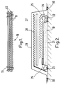
- the pre-form shown generally at 10 consists of layers of high-permeability fabric material 11 and layers of higher-density fabric material 12.
- the layers 11 act as resin distribution layers and the layers 12 act as structural reinforcement layers.
- the outer (lower-facing) layer 11 is intended to lie adjacent the substrate to be repaired or strengthened in use. The layers are loosely held together by stitching 13.
- the resin distribution layers 11 improve resin supply to the substrate and throughout the pre-form, whereas the structural reinforcement layers provide strength to the repair.
- Resin distribution layers 11 are formed from a biaxally woven polyester fibre; the initial or lower layer has a lower weave density than the central layer.
- the structural fibrous reinforcement layers 12 are formed from carbon fibres having mainly longitudinal fibres such that the flowpaths therein are predominantly longitudinally-oriented, whereas the layers 11 have predominantly transverse fibres such that the flowpaths are oriented to provide resin pathways having components directed perpendicularly to the plane of the layers and to the longitudinal direction.
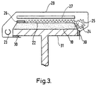
- the pre-form 10 is shown in position on one face of a plate substrate 21, optionally covered by a removable tear ply sheet 22.
- a suction channel 23 is disposed at one end of the pre-form and a resin supply pipe 24 is disposed at the other end, surrounded by a highly permeable resin distribution film layer 25 which extends across the top of the pre-form towards the suction channel 23.
- a resin block 26 is provided at the end adjacent the suction channel 23.
- a caul plate 27 is optionally disposed over the resin distribution layer 25 and is optionally overlaid with a conductive fabric layer 28.
- An impervious sheet 29 is placed over the entire assembly and is peripherally sealed to the substrate by use of double-sided adhesive tape or a mastic sealing compound 30. Connections to the conductive fabric and connections to a vacuum pump and resin reservoir (not shown) for the suction channel and resin supply pipe respectively are provided through the sheet 29 with suitable sealing.
- a suction is applied through the channel 23 and, when the desired reduced pressure has been achieved, resin is allowed to flow into the resin supply pipe 24. Resin is drawn therefrom and flows firstly through the resin distribution layers 25 and then into the pre-form layers, wetting out the fibres. When the desired quantity of resin has flowed into the system, the resin supply is stopped; alternatively, resin is allowed to continue to flow until gelling takes place.
- the conductive fabric may now be energised to generate heat for accelerating the curing stage or post-curing of the laminate.
- the pipes, caul sheet, impervious cover sheet, sealant tape and conductive fabric (unless required for service) may now be removed.
- the peelable tear ply layer may also be removed, either at this stage or before application of further reinforcement/resin distribution layers or painting.
- typical dimensions of the resulting composite reinforcement are 8m length, 500mm width and 35mm thickness.
- the reinforcement has excellent substrate adhesion and an excellent strength:weight ratio.
- Figure 3 and 4 show arrangements similar to that of Figure 2 as applied to the flange of a girder 31 ( Figure 3) and a tube 41 ( Figure 4).
- Typical dimensions for the strengthening of steel beams on an offshore oil production platform are 7m long by 0.2m wide reinforcing patches, each up to 54 layers thick; and for the repair of girth welds in pipelines using circumferential wraps of the reinforcing material, a patch 0.6m long by the circumference of the pipe, each wrap being up to 10 layers thick, may be used.
Landscapes
- Engineering & Computer Science (AREA)
- Architecture (AREA)
- Chemical & Material Sciences (AREA)
- Chemical Kinetics & Catalysis (AREA)
- Electrochemistry (AREA)
- Mechanical Engineering (AREA)
- Civil Engineering (AREA)
- Structural Engineering (AREA)
- Working Measures On Existing Buildindgs (AREA)
- Laminated Bodies (AREA)
- Reinforcement Elements For Buildings (AREA)
- Rod-Shaped Construction Members (AREA)
- Reinforced Plastic Materials (AREA)
- Forms Removed On Construction Sites Or Auxiliary Members Thereof (AREA)
- Moulds, Cores, Or Mandrels (AREA)
- Processing And Handling Of Plastics And Other Materials For Molding In General (AREA)
- Shaping Of Tube Ends By Bending Or Straightening (AREA)
- Moulding By Coating Moulds (AREA)
Claims (18)
- Verfahren zum Verstärken eines Substratbauelements (21), dadurch gekennzeichnet, daß das Verfahren die Schritte aufweistAufbringen von Schichten (12) auf eine Oberfläche (21) des Substrats, die Verstärkungsmaterial in Form von trockenen Faser aufweisen, die einen hohen Schlankheitsgrad haben und entsprechend den strukturellen Lasterfordernissen des Substratbauelements gerichtet angeordnet sindAnlegen eines reduzierten Drucks an die Materialschichten,Einführen eines härtbaren Harzes in die Schichten derart, daß das Harz hindurchgezogen wird, bis die Zwischenräume darin im wesentlichen mit Harz gefüllt sind, undHärten des Harzes.
- Verfahren nach Anspruch 1, bei welchem das Substrat eine anfänglich auf es aufgebrachte Schicht eines Primers oder Porenschließers hat.
- Verfahren nach Anspruch 1 oder Anspruch 2, bei welchem die Schichten Materialien mit unterschiedlicher Faseraufbaudichte und Permeabilität aufweisen, zu denen eine Schicht (11) eines ersten Materials mit einer relativ niedrigen Faseraufbaudichte und einer hohen Permeabilität angrenzend an das Substrat als Harzverteilungsschicht und eine oder mehrere weitere Schichten (12) mit einer höheren Faseraufbaudichte als strukturelle Verstärkungsschichten gehören.
- Verfahren nach einem vorhergehenden Anspruch, bei welchem die Fasern in den Verstärkungsmaterialien in unterschiedlichen Richtungen angeordnet sind.
- Verfahren nach Anspruch 3 oder Anspruch 4, bei welchem die strukturellen Verstärkungsschichten eine weitere Harzverteilungsschicht (11) in einer Zwischenposition aufweisen.
- Verfahren nach einem der Ansprüch 3 bis 5, bei welchem die Harzverteilungsschichten (11) eine offenere Faserverteilung als die strukturellen Verstärkungsschichten (12) aufweisen, so daß Harz in Richtungen strömt, die sowohl im wesentlichen parallel zu der Hauptachse der längs angeordneten Fasern und im wesentlichen senkrecht dazu sind.
- Verfahren nach einem vorhergehenden Anspruch, bei welchem das Harz eine Bindefestigkeit zwischen 15 und 30 MPa in Zugscherung und zwischen 15 und 35 MPa in reinem Zug hat.
- Verfahren nach einem vorhergehenden Anspruch, bei welchem die Faser aus Kohlestoffaser, Glas- oder einer anderen glasartigen Faser, aus thermoplatischer Faser, aus Aramidfaser, aus Polyethylen- und Polyesterfaser und aus Keramikfaser oder aus mehreren davon ausgewählt wird.
- Verfahren nach einem der Anspruch 3 bis 8, bei welchem das Material der Harzverteilungsschichten nicht gewebt ist und Baumwolle aufweist.
- Verfahren nach einem vorhergehenden Anspruch, bei welchem das Harz ein Polyestherharz, ein Epoxyharz, ein Phenolharz oder ein Vinylesterharz ist.
- Verfahren nach einem vorhergehenden Anspruch, bei welchem das Harz katalytisch, durch radikalischen Start oder durch Aufbringen von Wärme oder Feuchte gehärtet wird.
- Verfahren nach einem vorhergehenden Anspruch, bei welchem der reduzierte Druck auf ein Ende der Schichten bezüglich der Orientierungsrichtung der Hauptachsen der Fasern in dem faserenthaltenden Material aufgebracht und das Harz am anderen Ende eingeführt wird.
- Verfahren nach Anspruch 12, bei welchem das Harz über eine Harzverteilungsschicht (25) eingeführt wird, die am stromabseitigen Endbereich blockiert ist.
- Verfahren nach einem vorhergehenden Anspruch, welches die Verwendung einer entfernbaren Abschäl- oder Abreißlage (22), einer Schicht eines elektrisch leitenden Gewebes (28) und/oder einer Gesamt-Druckkissenbahn oder -platte (27) über den Verstärkungsschichten einschließt.
- Vorformling zur Verwendung bei der Verstärkung eines Substratbauelements, dadurch gekennzeichnet, daß der Vorformling eine Vielzahl von Schichten aus harzdurchläßigen trockenen Fasern mit einem hohen Schlankheitsgrad aufweist, wobei die Schichten lose zusammengeheftet sind und Harzverteilungsschichten (11) mit einer relativ niedrigen Faseraufbaudichte und hoher Permeabilität und Verstärkungsschichten (12) mit einer relativ hohen Faseraufbaudichte und einer niedrigen Permeabilität aufweisen.
- Vorformling nach Anspruch 15, bei welchem die Fasern in den Verstärkungsschichten in zwei bis vier unterschiedliche Richtungen fluchtend ausgerichtet sind.
- Vorformling nach Anspruch 15 oder Anspruch 16, bei welchem eine oder mehrere Harzverteilungsschichten für eine Anordnung bei der Verwendung an dem Substrat (21) und an einer oder mehreren Zwischenstellen durch die Schichten des Vorformlings vorgesehen sind.
- Vorformling nach einem der Ansprüche 15 bis 17 mit einem entfernbaren Dichtungsmaterial als Abschlußschicht.
Applications Claiming Priority (3)
| Application Number | Priority Date | Filing Date | Title |
|---|---|---|---|
| GBGB9501193.8A GB9501193D0 (en) | 1995-01-21 | 1995-01-21 | Reinforced material |
| GB9501193 | 1995-01-21 | ||
| PCT/GB1996/000121 WO1996022432A1 (en) | 1995-01-21 | 1996-01-22 | Reinforcement of structural members |
Publications (2)
| Publication Number | Publication Date |
|---|---|
| EP0827563A1 EP0827563A1 (de) | 1998-03-11 |
| EP0827563B1 true EP0827563B1 (de) | 1999-03-17 |
Family
ID=10768355
Family Applications (1)
| Application Number | Title | Priority Date | Filing Date |
|---|---|---|---|
| EP96900635A Expired - Lifetime EP0827563B1 (de) | 1995-01-21 | 1996-01-22 | Verstärkung von trägerteilen |
Country Status (14)
| Country | Link |
|---|---|
| US (1) | US5879778A (de) |
| EP (1) | EP0827563B1 (de) |
| JP (1) | JPH10513515A (de) |
| AT (1) | ATE177811T1 (de) |
| AU (1) | AU706549B2 (de) |
| CA (1) | CA2216631A1 (de) |
| DE (1) | DE69601791T2 (de) |
| DK (1) | DK0827563T3 (de) |
| ES (1) | ES2131924T3 (de) |
| GB (1) | GB9501193D0 (de) |
| GR (1) | GR3030285T3 (de) |
| NO (1) | NO307428B1 (de) |
| NZ (1) | NZ298854A (de) |
| WO (1) | WO1996022432A1 (de) |
Cited By (2)
| Publication number | Priority date | Publication date | Assignee | Title |
|---|---|---|---|---|
| US8281535B2 (en) | 2002-07-16 | 2012-10-09 | James Hardie Technology Limited | Packaging prefinished fiber cement articles |
| US8297018B2 (en) | 2002-07-16 | 2012-10-30 | James Hardie Technology Limited | Packaging prefinished fiber cement products |
Families Citing this family (18)
| Publication number | Priority date | Publication date | Assignee | Title |
|---|---|---|---|---|
| FR2747146B1 (fr) * | 1996-04-04 | 1998-07-10 | Freyssinet Int Stup | Procede de renforcement de structures de genie civil au moyen de fibres de carbone collees |
| US6357193B1 (en) * | 1998-12-17 | 2002-03-19 | Diversi-Plast Products, Inc. | Roof batten |
| US6231533B1 (en) * | 1999-05-21 | 2001-05-15 | Ppg Industries Ohio, Inc. | Orthopedic splinting article |
| US7018674B2 (en) * | 2001-03-02 | 2006-03-28 | Omron, Corporation | Manufacturing methods and apparatuses of an optical device and a reflection plate provided with a resin thin film having a micro-asperity pattern |
| US20090176020A1 (en) * | 2003-06-20 | 2009-07-09 | Vaerewyck Gerard J | Apparatus and method for treating and impregnating porous structures |
| US20050136239A1 (en) * | 2003-08-29 | 2005-06-23 | Eichinger Jeffrey D. | Multifunctional cryo-insulation apparatus and methods |
| IT1336868B1 (it) | 2004-02-13 | 2006-12-14 | Bonelli Walter | Procedimento di resinatura sottovuoto con strato drenante per blocchi di marmo |
| CN100457821C (zh) * | 2005-08-08 | 2009-02-04 | 陈金奎 | 改性夹布酚醛支承环、导向环及其制造方法 |
| JP4638850B2 (ja) * | 2006-09-05 | 2011-02-23 | Jx日鉱日石エネルギー株式会社 | 炭素繊維による既存構造物の補強方法 |
| DE602007007905D1 (de) * | 2007-05-07 | 2010-09-02 | Siemens Ag | Verfahren zur Herstellung eine Windturbinenschaufel |
| WO2010045100A2 (en) * | 2008-10-15 | 2010-04-22 | 3M Innovative Properties Company | Reinforcement patches with unidirectionally-aligned fibers |
| US20100119862A1 (en) * | 2008-11-10 | 2010-05-13 | Conocophillips Company | Fiber Wrapped Pipe Weld Seam |
| US9890546B2 (en) * | 2009-11-13 | 2018-02-13 | Mohammad Reza Ehsani | Reinforcement and repair of structural columns |
| JP6151047B2 (ja) * | 2013-03-01 | 2017-06-21 | 槌屋ティスコ株式会社 | 複合構造体の施工方法及び複合構造体 |
| DE102016106402A1 (de) * | 2016-04-07 | 2017-10-12 | Saertex Multicom Gmbh | Verfahren zum Verstärken von Bauteilen mit Verstärkungsfasern |
| JP7075343B2 (ja) * | 2017-04-25 | 2022-05-25 | 東レ株式会社 | 構造物へのfrp材の接着構造および接着方法 |
| KR101994852B1 (ko) * | 2017-11-21 | 2019-07-01 | 한국건설기술연구원 | 매립된 격자보강재를 갖는 보강패널을 이용한 콘크리트 구조물 및 그 보수 및 보강 방법 |
| FR3119631B1 (fr) | 2021-02-09 | 2023-11-24 | Soletanche Freyssinet | Procédé de renforcement d’une structure |
Family Cites Families (8)
| Publication number | Priority date | Publication date | Assignee | Title |
|---|---|---|---|---|
| CA994616A (en) * | 1972-11-01 | 1976-08-10 | Balfour, Beatty And Company Limited | Artificial and natural structures |
| GB1490102A (en) * | 1975-09-08 | 1977-10-26 | Balfour Beatty Ltd | Artificial and natural structures |
| GB1602859A (en) * | 1977-11-21 | 1981-11-18 | Balfour Beatty Ltd | Method of filling a hole in the ground |
| DE2909179C2 (de) * | 1979-03-08 | 1982-06-24 | Harry 2350 Neumünster Haase | Verfahren zur Erhöhung der Tragfähigkeit bestehender Stahlbetonkonstruktionen wie Stahlbeton-Silos |
| FR2594871B1 (fr) * | 1986-02-25 | 1990-10-12 | Sika Sa | Procede permettant de renforcer des structures ou elements de structure, notamment en beton, beton arme, beton precontraint a l'aide d'armatures souples, dispositif de mise en place des armatures, et armatures mises en oeuvre dans ledit procede |
| EP0378232B1 (de) * | 1989-01-12 | 1993-04-28 | Mitsubishi Kasei Corporation | Verfahren zur Verstärkung von Betonstrukturen |
| US5043033A (en) * | 1991-01-28 | 1991-08-27 | Fyfe Edward R | Process of improving the strength of existing concrete support columns |
| US5218810A (en) * | 1992-02-25 | 1993-06-15 | Hexcel Corporation | Fabric reinforced concrete columns |
-
1995
- 1995-01-21 GB GBGB9501193.8A patent/GB9501193D0/en active Pending
-
1996
- 1996-01-22 JP JP8522134A patent/JPH10513515A/ja not_active Ceased
- 1996-01-22 NZ NZ298854A patent/NZ298854A/xx unknown
- 1996-01-22 WO PCT/GB1996/000121 patent/WO1996022432A1/en not_active Ceased
- 1996-01-22 DE DE69601791T patent/DE69601791T2/de not_active Expired - Fee Related
- 1996-01-22 EP EP96900635A patent/EP0827563B1/de not_active Expired - Lifetime
- 1996-01-22 DK DK96900635T patent/DK0827563T3/da active
- 1996-01-22 AT AT96900635T patent/ATE177811T1/de not_active IP Right Cessation
- 1996-01-22 ES ES96900635T patent/ES2131924T3/es not_active Expired - Lifetime
- 1996-01-22 AU AU44542/96A patent/AU706549B2/en not_active Ceased
- 1996-01-22 CA CA002216631A patent/CA2216631A1/en not_active Abandoned
- 1996-01-22 US US08/875,119 patent/US5879778A/en not_active Expired - Fee Related
-
1997
- 1997-07-18 NO NO973333A patent/NO307428B1/no unknown
-
1999
- 1999-05-20 GR GR990401369T patent/GR3030285T3/el unknown
Cited By (2)
| Publication number | Priority date | Publication date | Assignee | Title |
|---|---|---|---|---|
| US8281535B2 (en) | 2002-07-16 | 2012-10-09 | James Hardie Technology Limited | Packaging prefinished fiber cement articles |
| US8297018B2 (en) | 2002-07-16 | 2012-10-30 | James Hardie Technology Limited | Packaging prefinished fiber cement products |
Also Published As
| Publication number | Publication date |
|---|---|
| DK0827563T3 (da) | 1999-10-11 |
| NZ298854A (en) | 1999-02-25 |
| ES2131924T3 (es) | 1999-08-01 |
| DE69601791T2 (de) | 1999-07-22 |
| GR3030285T3 (en) | 1999-09-30 |
| NO973333L (no) | 1997-08-28 |
| AU4454296A (en) | 1996-08-07 |
| ATE177811T1 (de) | 1999-04-15 |
| JPH10513515A (ja) | 1998-12-22 |
| DE69601791D1 (de) | 1999-04-22 |
| NO973333D0 (no) | 1997-07-18 |
| CA2216631A1 (en) | 1996-07-25 |
| US5879778A (en) | 1999-03-09 |
| WO1996022432A1 (en) | 1996-07-25 |
| EP0827563A1 (de) | 1998-03-11 |
| NO307428B1 (no) | 2000-04-03 |
| AU706549B2 (en) | 1999-06-17 |
| GB9501193D0 (en) | 1995-03-15 |
Similar Documents
| Publication | Publication Date | Title |
|---|---|---|
| AU706549B2 (en) | Strengthening of structural members | |
| US7096890B2 (en) | Inversion liner and liner components for conduits | |
| US5505030A (en) | Composite reinforced structures | |
| US5649398A (en) | High strength fabric reinforced walls | |
| US7179517B2 (en) | Sheet moulding compound (SMC) with ventilating structure for entrapped gases | |
| US7478650B2 (en) | Inversion liner and liner components for conduits | |
| US6837273B2 (en) | Inversion liner and liner components for conduits | |
| JP7075343B2 (ja) | 構造物へのfrp材の接着構造および接着方法 | |
| CA2413730C (en) | Structure reinforcing method, structure-reinforcing reinforcing fiber yarn-containing material, reinforcing structure material and reinforced structure | |
| WO2008086738A1 (fr) | Technique d'amélioration d'un mécanisme de pression par combinaison de la coulée d'un polymère durcissable à l'aide d'une bride avec un matériau composite renforcé par des fibres | |
| TW201943561A (zh) | 構造物之補強用積層材料、補強方法及補強構造體 | |
| US4897135A (en) | Method of reconstructing pipe systems using fiberglass laminates | |
| CN102575700B (zh) | 粘合组件及包含该组件使用的组装和增强方法 | |
| US20120261052A1 (en) | Method of rehabilitating or remediating structures | |
| US3424203A (en) | In-place repairs for concrete irrigation pipe | |
| JP2011104786A (ja) | ライニング材 | |
| KR100405033B1 (ko) | 복합소재의 진공성형 부착에 의한 콘크리트 구조물의보강방법 | |
| JP3477118B2 (ja) | 版状コンクリート構造体の補強方法 | |
| JP2826742B2 (ja) | 繊維強化プラスチック板を用いた構築物の補強方法 | |
| JP4681748B2 (ja) | 構造物の補強方法 | |
| JP2022040589A (ja) | 真空含浸成形方法。 | |
| CA2192567C (en) | High strength fabric reinforced walls | |
| JP3636748B2 (ja) | 構造物の補強方法 | |
| Trombeva-Gavriloska et al. | CONTEMPORARY METHODS FOR RECONSTRUCTION OF CONCRETE STRUCTURES | |
| JPH01195025A (ja) | 炭素繊維強化プラスチック板による構築物の強化方法 |
Legal Events
| Date | Code | Title | Description |
|---|---|---|---|
| PUAI | Public reference made under article 153(3) epc to a published international application that has entered the european phase |
Free format text: ORIGINAL CODE: 0009012 |
|
| GRAG | Despatch of communication of intention to grant |
Free format text: ORIGINAL CODE: EPIDOS AGRA |
|
| 17P | Request for examination filed |
Effective date: 19970821 |
|
| AK | Designated contracting states |
Kind code of ref document: A1 Designated state(s): AT BE CH DE DK ES FR GB GR IE IT LI LU MC NL PT SE |
|
| 17Q | First examination report despatched |
Effective date: 19980313 |
|
| GRAG | Despatch of communication of intention to grant |
Free format text: ORIGINAL CODE: EPIDOS AGRA |
|
| GRAH | Despatch of communication of intention to grant a patent |
Free format text: ORIGINAL CODE: EPIDOS IGRA |
|
| GRAH | Despatch of communication of intention to grant a patent |
Free format text: ORIGINAL CODE: EPIDOS IGRA |
|
| GRAA | (expected) grant |
Free format text: ORIGINAL CODE: 0009210 |
|
| AK | Designated contracting states |
Kind code of ref document: B1 Designated state(s): AT BE CH DE DK ES FR GB GR IE IT LI LU MC NL PT SE |
|
| DAX | Request for extension of the european patent (deleted) | ||
| REF | Corresponds to: |
Ref document number: 177811 Country of ref document: AT Date of ref document: 19990415 Kind code of ref document: T |
|
| REG | Reference to a national code |
Ref country code: CH Ref legal event code: EP |
|
| REG | Reference to a national code |
Ref country code: IE Ref legal event code: FG4D |
|
| REF | Corresponds to: |
Ref document number: 69601791 Country of ref document: DE Date of ref document: 19990422 |
|
| REG | Reference to a national code |
Ref country code: CH Ref legal event code: NV Representative=s name: TROESCH SCHEIDEGGER WERNER AG |
|
| ET | Fr: translation filed | ||
| REG | Reference to a national code |
Ref country code: ES Ref legal event code: FG2A Ref document number: 2131924 Country of ref document: ES Kind code of ref document: T3 |
|
| REG | Reference to a national code |
Ref country code: PT Ref legal event code: SC4A Free format text: AVAILABILITY OF NATIONAL TRANSLATION Effective date: 19990528 |
|
| REG | Reference to a national code |
Ref country code: DK Ref legal event code: T3 |
|
| PLBE | No opposition filed within time limit |
Free format text: ORIGINAL CODE: 0009261 |
|
| STAA | Information on the status of an ep patent application or granted ep patent |
Free format text: STATUS: NO OPPOSITION FILED WITHIN TIME LIMIT |
|
| 26N | No opposition filed | ||
| REG | Reference to a national code |
Ref country code: GB Ref legal event code: IF02 |
|
| PGFP | Annual fee paid to national office [announced via postgrant information from national office to epo] |
Ref country code: PT Payment date: 20020116 Year of fee payment: 7 |
|
| PGFP | Annual fee paid to national office [announced via postgrant information from national office to epo] |
Ref country code: ES Payment date: 20020122 Year of fee payment: 7 |
|
| PGFP | Annual fee paid to national office [announced via postgrant information from national office to epo] |
Ref country code: SE Payment date: 20020123 Year of fee payment: 7 |
|
| PGFP | Annual fee paid to national office [announced via postgrant information from national office to epo] |
Ref country code: LU Payment date: 20020128 Year of fee payment: 7 Ref country code: DK Payment date: 20020128 Year of fee payment: 7 |
|
| PGFP | Annual fee paid to national office [announced via postgrant information from national office to epo] |
Ref country code: BE Payment date: 20020129 Year of fee payment: 7 |
|
| PGFP | Annual fee paid to national office [announced via postgrant information from national office to epo] |
Ref country code: AT Payment date: 20020207 Year of fee payment: 7 |
|
| PGFP | Annual fee paid to national office [announced via postgrant information from national office to epo] |
Ref country code: MC Payment date: 20020305 Year of fee payment: 7 |
|
| PG25 | Lapsed in a contracting state [announced via postgrant information from national office to epo] |
Ref country code: LU Free format text: LAPSE BECAUSE OF NON-PAYMENT OF DUE FEES Effective date: 20030122 Ref country code: AT Free format text: LAPSE BECAUSE OF NON-PAYMENT OF DUE FEES Effective date: 20030122 |
|
| PG25 | Lapsed in a contracting state [announced via postgrant information from national office to epo] |
Ref country code: SE Free format text: LAPSE BECAUSE OF NON-PAYMENT OF DUE FEES Effective date: 20030123 Ref country code: ES Free format text: LAPSE BECAUSE OF NON-PAYMENT OF DUE FEES Effective date: 20030123 |
|
| PG25 | Lapsed in a contracting state [announced via postgrant information from national office to epo] |
Ref country code: MC Free format text: LAPSE BECAUSE OF NON-PAYMENT OF DUE FEES Effective date: 20030131 Ref country code: DK Free format text: LAPSE BECAUSE OF NON-PAYMENT OF DUE FEES Effective date: 20030131 Ref country code: BE Free format text: LAPSE BECAUSE OF NON-PAYMENT OF DUE FEES Effective date: 20030131 |
|
| PG25 | Lapsed in a contracting state [announced via postgrant information from national office to epo] |
Ref country code: PT Free format text: LAPSE BECAUSE OF NON-PAYMENT OF DUE FEES Effective date: 20030731 |
|
| EUG | Se: european patent has lapsed | ||
| REG | Reference to a national code |
Ref country code: DK Ref legal event code: EBP |
|
| REG | Reference to a national code |
Ref country code: ES Ref legal event code: FD2A Effective date: 20030123 |
|
| PGFP | Annual fee paid to national office [announced via postgrant information from national office to epo] |
Ref country code: GR Payment date: 20041229 Year of fee payment: 10 |
|
| PGFP | Annual fee paid to national office [announced via postgrant information from national office to epo] |
Ref country code: IE Payment date: 20041230 Year of fee payment: 10 |
|
| PGFP | Annual fee paid to national office [announced via postgrant information from national office to epo] |
Ref country code: CH Payment date: 20050119 Year of fee payment: 10 |
|
| PGFP | Annual fee paid to national office [announced via postgrant information from national office to epo] |
Ref country code: NL Payment date: 20050126 Year of fee payment: 10 |
|
| PGFP | Annual fee paid to national office [announced via postgrant information from national office to epo] |
Ref country code: FR Payment date: 20050131 Year of fee payment: 10 |
|
| PGFP | Annual fee paid to national office [announced via postgrant information from national office to epo] |
Ref country code: DE Payment date: 20050330 Year of fee payment: 10 |
|
| PG25 | Lapsed in a contracting state [announced via postgrant information from national office to epo] |
Ref country code: IE Free format text: LAPSE BECAUSE OF NON-PAYMENT OF DUE FEES Effective date: 20060123 |
|
| PG25 | Lapsed in a contracting state [announced via postgrant information from national office to epo] |
Ref country code: LI Free format text: LAPSE BECAUSE OF NON-PAYMENT OF DUE FEES Effective date: 20060131 Ref country code: FR Free format text: LAPSE BECAUSE OF NON-PAYMENT OF DUE FEES Effective date: 20060131 Ref country code: CH Free format text: LAPSE BECAUSE OF NON-PAYMENT OF DUE FEES Effective date: 20060131 |
|
| PGFP | Annual fee paid to national office [announced via postgrant information from national office to epo] |
Ref country code: IT Payment date: 20060131 Year of fee payment: 11 |
|
| PG25 | Lapsed in a contracting state [announced via postgrant information from national office to epo] |
Ref country code: NL Free format text: LAPSE BECAUSE OF NON-PAYMENT OF DUE FEES Effective date: 20060801 Ref country code: DE Free format text: LAPSE BECAUSE OF NON-PAYMENT OF DUE FEES Effective date: 20060801 |
|
| REG | Reference to a national code |
Ref country code: CH Ref legal event code: PL |
|
| NLV4 | Nl: lapsed or anulled due to non-payment of the annual fee |
Effective date: 20060801 |
|
| REG | Reference to a national code |
Ref country code: IE Ref legal event code: MM4A |
|
| REG | Reference to a national code |
Ref country code: FR Ref legal event code: ST Effective date: 20060929 |
|
| GBPC | Gb: european patent ceased through non-payment of renewal fee |
Effective date: 20070122 |
|
| PG25 | Lapsed in a contracting state [announced via postgrant information from national office to epo] |
Ref country code: GB Free format text: LAPSE BECAUSE OF NON-PAYMENT OF DUE FEES Effective date: 20070122 |
|
| PG25 | Lapsed in a contracting state [announced via postgrant information from national office to epo] |
Ref country code: GR Free format text: LAPSE BECAUSE OF NON-PAYMENT OF DUE FEES Effective date: 20060802 |
|
| PGFP | Annual fee paid to national office [announced via postgrant information from national office to epo] |
Ref country code: GB Payment date: 20060106 Year of fee payment: 11 |
|
| PG25 | Lapsed in a contracting state [announced via postgrant information from national office to epo] |
Ref country code: IT Free format text: LAPSE BECAUSE OF NON-PAYMENT OF DUE FEES Effective date: 20070122 |