EP0827704A2 - Meuble d'assise avec siège et dossier synchronisés - Google Patents
Meuble d'assise avec siège et dossier synchronisés Download PDFInfo
- Publication number
- EP0827704A2 EP0827704A2 EP97112802A EP97112802A EP0827704A2 EP 0827704 A2 EP0827704 A2 EP 0827704A2 EP 97112802 A EP97112802 A EP 97112802A EP 97112802 A EP97112802 A EP 97112802A EP 0827704 A2 EP0827704 A2 EP 0827704A2
- Authority
- EP
- European Patent Office
- Prior art keywords
- seat
- backrest
- support frame
- slot
- pair
- Prior art date
- Legal status (The legal status is an assumption and is not a legal conclusion. Google has not performed a legal analysis and makes no representation as to the accuracy of the status listed.)
- Granted
Links
Images



Classifications
-
- A—HUMAN NECESSITIES
- A47—FURNITURE; DOMESTIC ARTICLES OR APPLIANCES; COFFEE MILLS; SPICE MILLS; SUCTION CLEANERS IN GENERAL
- A47C—CHAIRS; SOFAS; BEDS
- A47C1/00—Chairs adapted for special purposes
- A47C1/02—Reclining or easy chairs
- A47C1/031—Reclining or easy chairs having coupled concurrently adjustable supporting parts
- A47C1/032—Reclining or easy chairs having coupled concurrently adjustable supporting parts the parts being movably-coupled seat and back-rest
- A47C1/03294—Reclining or easy chairs having coupled concurrently adjustable supporting parts the parts being movably-coupled seat and back-rest slidingly movable in the base frame, e.g. by rollers
-
- A—HUMAN NECESSITIES
- A47—FURNITURE; DOMESTIC ARTICLES OR APPLIANCES; COFFEE MILLS; SPICE MILLS; SUCTION CLEANERS IN GENERAL
- A47C—CHAIRS; SOFAS; BEDS
- A47C1/00—Chairs adapted for special purposes
- A47C1/02—Reclining or easy chairs
- A47C1/031—Reclining or easy chairs having coupled concurrently adjustable supporting parts
- A47C1/032—Reclining or easy chairs having coupled concurrently adjustable supporting parts the parts being movably-coupled seat and back-rest
- A47C1/03205—Reclining or easy chairs having coupled concurrently adjustable supporting parts the parts being movably-coupled seat and back-rest having adjustable and lockable inclination
- A47C1/0325—Reclining or easy chairs having coupled concurrently adjustable supporting parts the parts being movably-coupled seat and back-rest having adjustable and lockable inclination by means of clamps or friction locking members
Definitions
- the invention relates to a seating element or the like, in particular upholstered furniture element, with a coupled backrest and seat adjustment with the features of the preamble of claim 1.
- a seating element is also a seatable
- reclining furniture e.g. B. an upholstered lounger with a raised back section or an appropriate hospital bed.
- a seating element is known (FIGS. 1, 2 of WO 95/25 452) in which the Backrest with the seat forms an angularly rigid unit, which on the support frame by one Swivel axis below the seat is pivotally attached so that the backrest when tipping back into the lying position tilts back and down while the seat at the rear end down and of course at the front edge pivots above. This is usually done against the force of a return spring.
- a return spring interferes with the angularly rigid connection of the backrest and seat adjustment, so there is no extended position of the backrest and seat. It also disturbs that the front Edge of the seat in the lying position is moved up significantly, which the Legs of the user is not particularly beneficial.
- a construction of a seating element (Fig. 3, 4 of the WO 95/25 452), in which the supporting frame is designed like a frame.
- the backrest is hinged to the rear part of the frame-like support frame with considerable distance above a point of articulation of the backrest at the rear Edge of the seat.
- the rear edge of the seat is by means of the backrest on Carried frame.
- the seat is in guided a shift guide that has only a slight upward inclination, so that the front edge of the seat is in the transition from the sitting position to the lying position forward, but only slightly upwards.
- a disadvantage of the seating element is the pivot connection of the backrest and the seat roughly at the apex of the two elements.
- the connection Both elements are structurally simple, but both elements wear regularly Upholstery.
- the upholstery surfaces of the upholstery used by the user are therefore somewhat above the seat or in front of the backrest and thus somewhat above or in front of the swivel axis between the backrest and the seat has the consequence that when changing from the sitting position to the lying position, the cushion pads distance from each other, which is very uncomfortable for users perceived "shirt pull-out effect".
- the seating element has a significant advantage over the previously known Seating elements realized in that the articulation point of the backrest on Support frame not above the pivot point of the backrest on the seat, but considerably is provided below it. This also happens via a lever mechanism, wherein a knee joint connection an additional superimposed inclination movement the backrest realized.
- the seat itself is at a considerable distance from the pivot point of the backrest on the support frame near its front edge on Support frame articulated. Because this pivot point is near the front edge of the seat, the front edge of the seat rises when changing from the sitting position less in the lying position than in the state of the art known seating elements.
- the starting point for the teaching of the present invention is therefore the second one above Spot explained, particularly widespread variant of a seating element, at which swivels the backrest on the rear part of the frame-like support frame is articulated at a clear distance above an articulation point of the backrest at the rear of the seat.
- the invention is based on the problem while maintaining this basic principle, which in itself has the advantage of greatest simplicity has to make the "shirt pull-out effect” previously explained as small as possible and to close the "hole” in the pelvis / back area so that good support the pelvis / back area is also realized in a lying position.
- such a seating element is in the seating position It is immanent that a person sits with his hip when sitting correctly always in approximately the same place on the seat. Where exactly this place depends, of course, on various influencing factors, for example on the height of the cushion, the weight of the person, the height of the person and physique - male or female. On the whole you can say that the hip pivot point of a user's body is always in a relative narrow area is located above the seat and in front of the backrest.
- connection of the backrest with the seat in the area of Angle crest does not have a simple swivel joint with a connecting axis is realized, but via a double joint.
- connection mechanism with connection axes and slot settings ensures that the backrest is articulated on the lower, seat End at the transition from the sitting position to the lying position opposite the seat to the front, shifted to its front edge. The direction of this shift is opposite to the direction of the shift when moving from the sitting position in the lying position leads to the fact that the upholstery pads are separated from each other remove.
- the invention is characterized in that the construction is relatively simple and can be set up inexpensively so that the suspension can be carried out as before, in principle, the support frames previously used for known seating furniture elements can continue to use, and that the articulation points are well hidden can.
- FIGS. 1 and 2 Seating furniture element or the like is, as a rule and according to the preferred embodiment, an upholstered furniture element, especially an upholstered armchair or part of a multi-seat upholstered couch. But that does not mean that the seating element is not in principle can also be realized without upholstery, for example as a garden seating element made of plastic or wood. As mentioned above, relates the invention relates to seating furniture elements in the most general understanding, that is, elements with seat and backrest, the adjustments of which are coupled.
- Two-seater sofas or three-seater sofas, possibly also around reclining furniture that is seatable are, for example, hospital beds with a raised back or act corresponding upholstered beds.
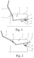
- the seating element shown in FIGS. 1 and 2 has a coupled backrest and Seat adjustment on.
- a backrest 2 and a seat 3 designed as an upholstered armchair.
- the backrest 2 is articulated on the support frame 1 on a pivot axis 4, this pivot axis 4 being continuous or arranged on both sides Axis sections can be formed, preferably by the latter.
- the backrest 2 is movable with the seat 3 in the area of the angle apex via a swivel joint connected.
- the backrest 2 leads to the support frame 1 from the highest, erect Position, the sitting position, in the lowest, stretched position, the lying position, a superimposed tilting and lowering movement.
- Fig. 1 does this in comparison with Fig. 2 clearly.
- the seat 3 leads from the sitting position to the lying position synchronizes a slight movement, namely the one already explained overlaid displacement and lifting movement.
- a lifting movement of the seat 3 in the transition from the sitting position to the lying position has the result that a user's weight shift when trying to get back into the sitting position erect, is used that the seat 3 by the higher weight of the User is pressed down and thereby the backrest 2, if necessary supported by a return spring, straightens up again. Without any relocation the seat 5 is in this type of seating element with coupled Backrest and seat adjustment is not obvious.
- the hip pivot 7 of the body of a seated average person indicated. He is in a certain position when sitting correctly Position above the seat 3, in the sitting position in a certain position in front of the backrest 2. As has already been explained in the general part of the description, the hip pivot point 7 shifts during the transition from the sitting position to the lying position compared to the seat 3 or not at all.
- the aim of the invention is a to achieve a correspondingly low displacement relative to the backrest 2, so as to reduce the "shirt pull-out effect".
- FIGS 3 and 4 show a seating element of the starting point for the teaching of the prior art.
- the basic concept of those met there The articulation of the backrest 2 and seat 3 should in principle be retained. Proceeding from this, the invention is shown in a first exemplary embodiment in FIGS 3 and 4 shown way. There is shown the position of the backrest 2 and Seat 3 in the sitting position in solid lines and in the reclining position in dash-dotted lines Lines.
- the connection of the backrest 2 with the seat 3 in the area of Angle apex has changed significantly. For the sake of completeness, it is allowed are pointed out that as a rule such a connection on each side of Backrest 2 and seat 3 is realized, that is to the right and left of backrest 2 and Seat 3, or only in one place, namely approximately in the middle.
- connection has two connection axes 8, 9, which are in two slot settings 10, 11 run. It can be seen that the first pair 8, 10 from the connecting axis 8 and slot hole 10 is arranged at the rear edge of the seat 3 and that the Backrest 2 extends up to here. It can also be seen that the second pair 9, 11 out Connection axis 9 and slot 11 at the rear edge of the seat 3 at a distance is arranged above the first pair 8, 10.
- the representation in Fig. 3 makes particularly clear that the backrest 2 in the transition from sitting position in Lying position below the pivot axis 4 is shifted more forward than the seat 3. The resulting relative movement between the lower edge of the backrest 2 and the seat 3 is by the first pair 8, 10 from the connecting axis 8 and slot setting 10 added.
- the "shirt pull-out effect” is significantly reduced, the "hole” in the lumbar region that occurs during the transition to the lying position is reduced to a comfortable level.
- the embodiment is further characterized in that the sitting position and the lying position by the end positions of the connecting axes 8, 9 in the slot settings 10, 11 are defined.
- FIG. 4 makes it clear that a specific position for the second pair 9, 11 is preferred brings particularly positive effects.
- the second pair 9, 11 from connecting axis 9 and In this exemplary embodiment, slot opening 11 is approximately in the middle the distance between the pivot axis 4 and the first pair 8, 10 arranged. If, as shown, the first pair 8, 10 is arranged approximately on the underside of the seat 3, it is further recommended that the second pair 9, 11 approximately at the top a cushion pad 12 is arranged on the seat 3.
- Fig. 4 shows how the front of the cushion cover 12 on the backrest 2 when transitioning to the lying position over the rear End of the cushion pad 12 of the seat 3 and thus the lumbar region supported by the user.
- connecting axes and slot settings to the two with each other coupled parts, namely backrest 2 and seat 3, is in principle free to determine.
- the exemplary embodiment shown is characterized by that the first connecting axis 8 on the backrest 2 and the first slot setting 10 is arranged on the seat 3, while the second connecting axis 9 on the seat 3 and the second slot setting 11 is arranged on the backrest 2.
- the second Pair 9, 11 of connecting axis 9 and slot 11 serves essentially the Compensation for the relative movement of the backrest 2 and seat 3 to each other The consequence of the displacement of the connecting axis 8 in the slot 10 is.
- Fig. 3 and 4 shows that here the first slot setting 10 runs straight and is aligned approximately parallel to the plane of the seat 3.
- the second slot setting 11 runs straight and, preferably, is oriented approximately perpendicular to the plane of the seat 3 in the sitting position.
- the slot 10 inclined to the level of the seat 3, namely To be arranged rising from the rear to the front end. Such an inclination leads to a changed movement of the backrest 2 relative to the seat 3 depending on the desired application, but also depending on the design and upholstery of backrest 2 and seat 3.
- Fig. 3 shows dashed lines on the front edge of the seat 3, the inclination the corresponding slide rail 6, which is part of the support mechanism. This tendency can be about 40 ° to the ground, the angle of inclination should be chosen that a user the front edge of the seat 3 when transitioning to the lying position does not get pressed too far into the back of the knee. A little raise there is pleasant, too much is not pleasant.
- the shift at the front of the Seat 3 largely follows the design of the connection area in the Angle apex.
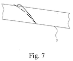
- Fig. 7 shows the area of the front edge of the seat 3 in a schematic representation and drawn in there the displacement of a certain point on the front Edge of the seat 3 at the transition from the sitting position to the lying position.
- the solid line shows the shift of this point in the embodiment with straight slot setting 10 according to FIG. 3, 4.
- This point is about 5 ° before reaching the lying position. This effect is as The user also "tilts" the seating element known from the prior art known as distracting.
- Fig. 7 makes it clear where the particular advantage of the arc-shaped concave slot setting 10 of the embodiment of FIGS. 5 and 6.
- the dash-dotted Line in Fig. 7 gives the course of the corresponding point when using an arc-concave Slotted backdrop 10 again.
- the "tipping effect" is practical here eliminates a smooth, comfortable movement of the backrest 2 when standing up the result is the lying position.
- Fig. 6 makes it clear that the parts associated with the backrest 2, in particular So the first connecting axis 8 and the second slot 11 in a backrest fitting 13 are summarized. Accordingly, the seat 3 assigned parts, in particular the second connecting axis 9 and the first Slotted hole backdrop 10 combined in a seat fitting 14.
- the backrest fitting 13 and the seat fitting 14 are together in the illustrated embodiment connected, thus form a single, manageable component which, not shown here, can be enclosed by a housing.
- each such a total fitting is arranged on the left and right of the support frame 1, wherein expediently used two mirror-symmetrically arranged overall fittings will. In principle, a single one arranged in the middle would also be conceivable Total fitting between backrest 2 and seat 3 or two individual fittings - Backrest fitting and seat fitting - approximately in the middle between the backrest 2 and seat 3.
- FIG. 3 shows, moreover, that even with this concept the backrest 2 is bent backwards approximately at the level of the pivot axis 4, what the comfortable lying position does.
- FIG. 8 shows an alternative solution of a likewise expediently designed "shirt pull-out effect" reducing seating element, in which the reference numerals explained above as far as reasonable. In this respect, additional needs are required No explanations.
- connection of the backrest 2 with the Seat 3 in the area of the angle apex on each side three connecting axes 15, 16, 17 and an elongated hole backdrop 18 that the first connecting axis 15 in the Slotted backdrop 18 runs and this pair 15, 18 in front of the rear edge of the seat 3rd is arranged that the second connecting axis 16 on the backrest 2 at a distance is arranged above the pair 15, 18 that at the rear edge of the seat 3rd the third connection axis 17 is arranged and that the second connection axis 16 and the third connecting axle 17 are connected to one another via an auxiliary link 19 are.
- the representation of the sitting position in solid lines and the lying position in dash-dotted lines shows what the auxiliary link 19 does here.
- the seat 3 is opposite the backrest during the transition to the lying position 2 withdrawn, part of the shift causing the "shirt pull-out" effect the backrest 2 opposite the seat is thus reversed made or compensated.
- FIG. 9 shows a last exemplary embodiment with a further variant, for it is provided that the connection of the backrest 2 with the seat 3 in the area of the angled apex on each side over one between the end of the backrest 2 and the end of the seat 3 extending, hinged on both sides
- Auxiliary link 20 is realized.
- This auxiliary link 20 created a similar to a knee joint Connection between the backrest 2 and seat 3, which is a pendulum movement of the Seat 3 allowed in the transition to the lying position, which also shows, as Fig. 9 shows the displacement of the backrest 2 partially compensated for the seat 3.
- FIGS. 1 and 2 The input of the special part of the description is to the representation in FIGS. 1 and 2 have been noted that the front edge of the seat 3 on a crossbar 5 is mounted by means of a slide rail 6.
- a known one is shown there Braking device 21, which allows a defined braking effect to be set, so that the movement of the seating element between the sitting position and lying position can influence sensitively or can also determine individual positions.
- Such a braking device 21 should of course also be measured in the seating element the invention can be implemented, for which reference is made to the prior art may.
- seating element in particular upholstered furniture element generally as single products armchairs, upholstered armchairs, recliners, but also multi-seaters Upholstered furniture, which then has the previously explained adjustability in each individual seat exhibit.
- Such seating furniture elements are also aircraft seats, for example or seats in comfortable coaches and other means of transport. Also for others Such seating elements can be used in relaxation areas.
Landscapes
- Health & Medical Sciences (AREA)
- Dentistry (AREA)
- General Health & Medical Sciences (AREA)
- Chairs For Special Purposes, Such As Reclining Chairs (AREA)
- Seats For Vehicles (AREA)
- Chairs Characterized By Structure (AREA)
- Chair Legs, Seat Parts, And Backrests (AREA)
Applications Claiming Priority (4)
| Application Number | Priority Date | Filing Date | Title |
|---|---|---|---|
| DE19636218 | 1996-09-06 | ||
| DE19636218 | 1996-09-06 | ||
| DE19639741A DE19639741C2 (de) | 1996-09-06 | 1996-09-27 | Sitzmöbelelement, insbesondere Polstermöbelelement, mit einer gekoppelten Rückenlehnen- und Sitzverstellung |
| DE19639741 | 1996-09-27 |
Publications (3)
| Publication Number | Publication Date |
|---|---|
| EP0827704A2 true EP0827704A2 (fr) | 1998-03-11 |
| EP0827704A3 EP0827704A3 (fr) | 2000-01-12 |
| EP0827704B1 EP0827704B1 (fr) | 2002-05-08 |
Family
ID=26029115
Family Applications (1)
| Application Number | Title | Priority Date | Filing Date |
|---|---|---|---|
| EP97112802A Expired - Lifetime EP0827704B1 (fr) | 1996-09-06 | 1997-07-25 | Meuble d'assise avec siège et dossier synchronisés |
Country Status (7)
| Country | Link |
|---|---|
| US (1) | US5860701A (fr) |
| EP (1) | EP0827704B1 (fr) |
| JP (1) | JP3162325B2 (fr) |
| CN (1) | CN1131692C (fr) |
| AT (1) | ATE217161T1 (fr) |
| CA (1) | CA2213760C (fr) |
| DE (2) | DE19639741C2 (fr) |
Cited By (3)
| Publication number | Priority date | Publication date | Assignee | Title |
|---|---|---|---|---|
| US6679556B1 (en) | 1999-03-01 | 2004-01-20 | Kjartan Alvestad | Arrangement for beds and other reclining or seating furniture |
| WO2008004583A1 (fr) | 2006-07-07 | 2008-01-10 | Maruichi Selling Inc. | Structure de chaise inclinable |
| CN102860684A (zh) * | 2012-09-10 | 2013-01-09 | 上海理工大学 | 手动多姿态椅 |
Families Citing this family (40)
| Publication number | Priority date | Publication date | Assignee | Title |
|---|---|---|---|---|
| NO306753B1 (no) * | 1995-12-18 | 1999-12-20 | Opsvik Peter As | Reguleringsanordning for stol |
| US6237872B1 (en) | 1997-02-14 | 2001-05-29 | Reuven Bar-Levav | Aircraft cabin environment |
| USD448277S1 (en) | 2000-09-28 | 2001-09-25 | Formway Furniture Limited | Castor |
| USD460300S1 (en) | 2000-09-28 | 2002-07-16 | Formway Furniture Limited | Slotted seat panel for a chair |
| USD463144S1 (en) | 2000-09-28 | 2002-09-24 | Formway Furniture Limited | Chair |
| AU783829B2 (en) | 2000-09-28 | 2005-12-08 | Formway Furniture Limited | A reclinable chair |
| USD446397S1 (en) | 2000-09-28 | 2001-08-14 | Formway Furniture Limited | Chair |
| USD445580S1 (en) | 2000-09-28 | 2001-07-31 | Formway Furniture Limited | Chair |
| USD448219S1 (en) | 2000-09-28 | 2001-09-25 | Formway Furniture Limited | Castored base for a chair |
| AUPR054400A0 (en) | 2000-09-29 | 2000-10-26 | Formway Furniture Limited | A castor |
| WO2002032264A1 (fr) * | 2000-10-16 | 2002-04-25 | Kokuyo Co., Ltd. | Chaise |
| US6609755B2 (en) * | 2001-06-15 | 2003-08-26 | Hon Technology Inc. | Ergonomic chair |
| KR100418735B1 (ko) * | 2001-08-31 | 2004-02-18 | 미래종합상사(주) | 의자의 등받이 구동 장치 |
| ES2192476B2 (es) * | 2002-01-18 | 2004-06-01 | Sebastian Aramburu Echevarria | Sillon reclinable. |
| NZ518944A (en) * | 2002-05-14 | 2004-09-24 | Formway Furniture Ltd | Height adjustable arm for chair with outer stem releasably lockable to inner stem by engagement of recesses |
| DE60200399T2 (de) * | 2002-07-24 | 2005-05-04 | Ciar S.P.A., Borgo Santa Maria | Sitzmöbel mit einem Sitz und einer Rückenlehne |
| US7458637B2 (en) * | 2004-06-10 | 2008-12-02 | Steelcase Inc. | Back construction with flexible lumbar |
| US7237841B2 (en) * | 2004-06-10 | 2007-07-03 | Steelcase Development Corporation | Back construction with flexible lumbar |
| US7422287B2 (en) * | 2005-03-08 | 2008-09-09 | Steelcase Inc. | Seating with shape-changing back support frame |
| USD555377S1 (en) | 2006-02-24 | 2007-11-20 | Steelcase Development Corporation | Seating unit |
| US20110025111A1 (en) * | 2007-12-20 | 2011-02-03 | David Wornell | Seating systems incorporating self-inflating adjustable supports |
| DE102011010099A1 (de) * | 2011-02-01 | 2012-08-02 | Bock 1 Gmbh & Co. Kg | Synchronmechanik |
| BR122015025310B1 (pt) | 2011-10-04 | 2021-01-12 | Formway Furniture Limited | cadeira |
| US9714095B2 (en) | 2011-10-07 | 2017-07-25 | Bombardier Inc. | Aircraft seat |
| US9073453B2 (en) | 2011-10-07 | 2015-07-07 | Bombardier Inc. | Aircraft seat |
| US9592914B2 (en) | 2011-10-07 | 2017-03-14 | Bombardier Inc. | Aircraft seat |
| US9714862B2 (en) | 2011-10-07 | 2017-07-25 | Bombardier Inc. | Aircraft seat |
| US10583926B2 (en) | 2014-09-25 | 2020-03-10 | Bombardier Inc. | Aircraft seat |
| US10106261B2 (en) * | 2015-06-29 | 2018-10-23 | Zodiac Seat US LLC | Ramp mount |
| CN105902003B (zh) * | 2016-05-20 | 2019-04-05 | 永艺家具股份有限公司 | 一种休闲椅 |
| DE202016105769U1 (de) * | 2016-10-14 | 2016-11-10 | Topstar Gmbh | Sitzmöbel |
| DE202016107139U1 (de) * | 2016-12-19 | 2017-04-25 | Dietmar Kaczikowski | Stuhl, vorzugsweise Drehstuhl |
| CA3086225A1 (fr) | 2017-12-21 | 2019-06-27 | Bombardier Inc. | Siege passager inclinable |
| US11589678B2 (en) | 2019-01-17 | 2023-02-28 | Hni Technologies Inc. | Chairs including flexible frames |
| WO2020204877A1 (fr) * | 2019-03-29 | 2020-10-08 | Safran Seats Usa Llc | Plateau inférieur articulé à panneau en sandwich plat |
| CN110664148A (zh) * | 2019-04-18 | 2020-01-10 | 北京大倪实业有限公司 | 一种折叠式座椅 |
| CA3057933A1 (fr) * | 2019-10-08 | 2021-04-08 | Steven Pearse | Fauteuil ayant un siege et un dossier basculants |
| US11178970B1 (en) * | 2020-09-29 | 2021-11-23 | L&P Property Management Company | High-leg hidden ottoman recliner seating mechanism |
| CA3178812A1 (fr) | 2021-10-08 | 2023-04-08 | Bombardier Inc. | Siege inclinable a configurations multiples |
| CN115534776B (zh) * | 2022-10-13 | 2026-02-10 | 宁波宝贝第一母婴用品有限公司 | 安全座椅 |
Family Cites Families (19)
| Publication number | Priority date | Publication date | Assignee | Title |
|---|---|---|---|---|
| GB768235A (en) * | 1953-10-21 | 1957-02-13 | John Watson | Improvements in or relating to chairs |
| US3337266A (en) * | 1966-02-01 | 1967-08-22 | Belvedere Products Inc | Compensating back chair |
| FR1596508A (fr) * | 1968-07-18 | 1970-06-22 | ||
| ZA756831B (en) * | 1975-10-29 | 1976-10-27 | Kiang Piao | Tv chair with double pillow case and two-step ottoman |
| DE2916897A1 (de) * | 1979-04-07 | 1980-11-06 | Otto Zapf | Sitzmoebel |
| CH641658A5 (en) * | 1979-11-14 | 1984-03-15 | Drabert Soehne | Chair, in particular for operating visual display units |
| DE8025516U1 (de) * | 1980-09-24 | 1981-01-15 | Zapf, Otto, 6240 Koenigstein | Sitzmoebel |
| FR2527061B1 (fr) * | 1982-05-19 | 1985-11-15 | Ami | Siege articule |
| IT8323779U1 (it) * | 1983-12-06 | 1985-06-06 | B & B Italia Spa | Sedia da lavoro composizione di seduta regolabile e schienale flessibile |
| DE3429186A1 (de) * | 1984-08-08 | 1986-02-20 | Uredat-Neuhoff, Angela, 4592 Lindern | Sitzmoebel, insbesondere buerostuhl |
| EP0198056B1 (fr) * | 1984-10-25 | 1991-01-09 | Konrad Neumüller | Support de siege pour chaises, surtout pour des chaises de travail |
| FR2575051B1 (fr) * | 1984-12-21 | 1987-02-27 | Linguanotto Ets | Siege, notamment siege de travail, a plusieurs positions |
| DE59006985D1 (de) * | 1989-12-29 | 1994-10-06 | Wilkhahn Wilkening & Hahne | Synchronverstelleinrichtung für bürostühle oder dergleichen. |
| US5131717A (en) * | 1990-09-28 | 1992-07-21 | The Pelton & Crane Company | Reclining chair having a movable seat back and a movable seat bottom |
| US5209549A (en) * | 1991-05-28 | 1993-05-11 | Chang I Shan | Adjustable rotation chair |
| JP2627240B2 (ja) * | 1993-02-24 | 1997-07-02 | 池田物産株式会社 | 車両用シート |
| DE9311345U1 (de) * | 1993-07-29 | 1993-09-23 | Eubel, Karl, 96242 Sonnefeld | Stuhl |
| DK9400143U3 (da) * | 1994-03-18 | 1994-07-22 | P Schultz & Co As | Beslag til synkron regulering af sæde og ryg i stole |
| US5636898A (en) * | 1994-04-15 | 1997-06-10 | Burns Aerospace Corporation | Seat with recline linkage |
-
1996
- 1996-09-27 DE DE19639741A patent/DE19639741C2/de not_active Expired - Fee Related
-
1997
- 1997-07-25 AT AT97112802T patent/ATE217161T1/de not_active IP Right Cessation
- 1997-07-25 EP EP97112802A patent/EP0827704B1/fr not_active Expired - Lifetime
- 1997-07-25 DE DE59707203T patent/DE59707203D1/de not_active Expired - Fee Related
- 1997-08-26 US US08/917,550 patent/US5860701A/en not_active Expired - Fee Related
- 1997-09-05 CA CA002213760A patent/CA2213760C/fr not_active Expired - Fee Related
- 1997-09-06 CN CN97121373.9A patent/CN1131692C/zh not_active Expired - Fee Related
- 1997-09-08 JP JP24303097A patent/JP3162325B2/ja not_active Expired - Fee Related
Cited By (5)
| Publication number | Priority date | Publication date | Assignee | Title |
|---|---|---|---|---|
| US6679556B1 (en) | 1999-03-01 | 2004-01-20 | Kjartan Alvestad | Arrangement for beds and other reclining or seating furniture |
| WO2008004583A1 (fr) | 2006-07-07 | 2008-01-10 | Maruichi Selling Inc. | Structure de chaise inclinable |
| EP2039265A4 (fr) * | 2006-07-07 | 2010-08-18 | Maruichi Selling Inc | Structure de chaise inclinable |
| CN102860684A (zh) * | 2012-09-10 | 2013-01-09 | 上海理工大学 | 手动多姿态椅 |
| CN102860684B (zh) * | 2012-09-10 | 2015-07-22 | 上海理工大学 | 手动多姿态椅 |
Also Published As
| Publication number | Publication date |
|---|---|
| US5860701A (en) | 1999-01-19 |
| JPH10165252A (ja) | 1998-06-23 |
| CA2213760C (fr) | 2002-01-15 |
| ATE217161T1 (de) | 2002-05-15 |
| DE19639741A1 (de) | 1998-03-19 |
| EP0827704A3 (fr) | 2000-01-12 |
| EP0827704B1 (fr) | 2002-05-08 |
| CA2213760A1 (fr) | 1998-03-06 |
| JP3162325B2 (ja) | 2001-04-25 |
| CN1131692C (zh) | 2003-12-24 |
| DE19639741C2 (de) | 1998-07-09 |
| CN1194125A (zh) | 1998-09-30 |
| DE59707203D1 (de) | 2002-06-13 |
| MX9706723A (es) | 1998-06-30 |
Similar Documents
| Publication | Publication Date | Title |
|---|---|---|
| EP0827704B1 (fr) | Meuble d'assise avec siège et dossier synchronisés | |
| EP0826327B1 (fr) | Meuble d'assise avec siège et dossier synchronisé | |
| EP0540711B1 (fr) | Siege de travail, notamment siege de bureau | |
| DE69122268T2 (de) | Stuhl für körperlich behinderte personen | |
| DE3930983C2 (de) | Sitzmöbel mit neigungsverstellbarer Sitzfläche | |
| DE69826554T2 (de) | Lehnstuhl | |
| DE3632131A1 (de) | Funktions-sitzmoebel | |
| DE2820063A1 (de) | Stuhl | |
| DE2057980A1 (de) | Kippsessel | |
| DE2026929A1 (de) | Stuhl mit sich automatisch anpassender Rückenlehne | |
| AT12867U1 (de) | Sitzmöbel | |
| DE3844128A1 (de) | Bettcouch | |
| DE202020101493U1 (de) | Winkelverstellanordnung eines Toiletten- und Duschstuhls | |
| DE102006039278B4 (de) | Verwandelbarer Sitz-/Liegestuhl | |
| DE8419826U1 (de) | Verstell-Stuhl | |
| DE4333219A1 (de) | Zurückneigbarer Stuhl | |
| DE4225286A1 (de) | Sitz- und Liegemöbel | |
| DE3402839C2 (de) | Klappsessel oder Liegestuhl | |
| DE8912125U1 (de) | Sitzmöbel, insbesondere Stuhl | |
| DE3239356A1 (de) | Sitz fuer einen stuhl, sessel oder dgl. | |
| EP4056072B1 (fr) | Siège | |
| DE29707354U1 (de) | Stuhl | |
| DE202007006432U1 (de) | Sitzmöbel mit schwenkbarer Rückenlehne | |
| DE202006006765U1 (de) | Ein- oder mehrsitziges Sitzmöbel | |
| DE4437731C2 (de) | Stuhl mit neigbarer Sitzfläche |
Legal Events
| Date | Code | Title | Description |
|---|---|---|---|
| PUAI | Public reference made under article 153(3) epc to a published international application that has entered the european phase |
Free format text: ORIGINAL CODE: 0009012 |
|
| AK | Designated contracting states |
Kind code of ref document: A2 Designated state(s): AT BE CH DE FR LI NL |
|
| PUAL | Search report despatched |
Free format text: ORIGINAL CODE: 0009013 |
|
| AK | Designated contracting states |
Kind code of ref document: A3 Designated state(s): AT BE CH DE DK ES FI FR GB GR IE IT LI LU MC NL PT SE |
|
| 17P | Request for examination filed |
Effective date: 19991223 |
|
| AKX | Designation fees paid |
Free format text: AT BE CH DE FR LI NL |
|
| GRAG | Despatch of communication of intention to grant |
Free format text: ORIGINAL CODE: EPIDOS AGRA |
|
| 17Q | First examination report despatched |
Effective date: 20011017 |
|
| GRAG | Despatch of communication of intention to grant |
Free format text: ORIGINAL CODE: EPIDOS AGRA |
|
| GRAG | Despatch of communication of intention to grant |
Free format text: ORIGINAL CODE: EPIDOS AGRA |
|
| GRAH | Despatch of communication of intention to grant a patent |
Free format text: ORIGINAL CODE: EPIDOS IGRA |
|
| GRAA | (expected) grant |
Free format text: ORIGINAL CODE: 0009210 |
|
| AK | Designated contracting states |
Kind code of ref document: B1 Designated state(s): AT BE CH DE FR LI NL |
|
| REF | Corresponds to: |
Ref document number: 217161 Country of ref document: AT Date of ref document: 20020515 Kind code of ref document: T |
|
| REG | Reference to a national code |
Ref country code: CH Ref legal event code: NV Representative=s name: KELLER & PARTNER PATENTANWAELTE AG Ref country code: CH Ref legal event code: EP |
|
| REF | Corresponds to: |
Ref document number: 59707203 Country of ref document: DE Date of ref document: 20020613 |
|
| ET | Fr: translation filed | ||
| PLBE | No opposition filed within time limit |
Free format text: ORIGINAL CODE: 0009261 |
|
| STAA | Information on the status of an ep patent application or granted ep patent |
Free format text: STATUS: NO OPPOSITION FILED WITHIN TIME LIMIT |
|
| 26N | No opposition filed |
Effective date: 20030211 |
|
| PGFP | Annual fee paid to national office [announced via postgrant information from national office to epo] |
Ref country code: FR Payment date: 20090716 Year of fee payment: 13 |
|
| PGFP | Annual fee paid to national office [announced via postgrant information from national office to epo] |
Ref country code: NL Payment date: 20090730 Year of fee payment: 13 Ref country code: DE Payment date: 20090923 Year of fee payment: 13 Ref country code: CH Payment date: 20090715 Year of fee payment: 13 Ref country code: AT Payment date: 20090715 Year of fee payment: 13 |
|
| PGFP | Annual fee paid to national office [announced via postgrant information from national office to epo] |
Ref country code: BE Payment date: 20090818 Year of fee payment: 13 |
|
| BERE | Be: lapsed |
Owner name: *JUNGJOHANN THOMAS Effective date: 20100731 |
|
| REG | Reference to a national code |
Ref country code: NL Ref legal event code: V1 Effective date: 20110201 |
|
| REG | Reference to a national code |
Ref country code: CH Ref legal event code: PL |
|
| REG | Reference to a national code |
Ref country code: FR Ref legal event code: ST Effective date: 20110331 |
|
| PG25 | Lapsed in a contracting state [announced via postgrant information from national office to epo] |
Ref country code: DE Free format text: LAPSE BECAUSE OF NON-PAYMENT OF DUE FEES Effective date: 20110201 Ref country code: LI Free format text: LAPSE BECAUSE OF NON-PAYMENT OF DUE FEES Effective date: 20100731 Ref country code: CH Free format text: LAPSE BECAUSE OF NON-PAYMENT OF DUE FEES Effective date: 20100731 |
|
| REG | Reference to a national code |
Ref country code: DE Ref legal event code: R119 Ref document number: 59707203 Country of ref document: DE Effective date: 20110201 |
|
| PG25 | Lapsed in a contracting state [announced via postgrant information from national office to epo] |
Ref country code: FR Free format text: LAPSE BECAUSE OF NON-PAYMENT OF DUE FEES Effective date: 20100802 Ref country code: NL Free format text: LAPSE BECAUSE OF NON-PAYMENT OF DUE FEES Effective date: 20110201 Ref country code: AT Free format text: LAPSE BECAUSE OF NON-PAYMENT OF DUE FEES Effective date: 20100725 |
|
| PG25 | Lapsed in a contracting state [announced via postgrant information from national office to epo] |
Ref country code: BE Free format text: LAPSE BECAUSE OF NON-PAYMENT OF DUE FEES Effective date: 20100731 |