EP0827773A1 - Kompressions- und Gastrocknungszentrale - Google Patents
Kompressions- und Gastrocknungszentrale Download PDFInfo
- Publication number
- EP0827773A1 EP0827773A1 EP97420159A EP97420159A EP0827773A1 EP 0827773 A1 EP0827773 A1 EP 0827773A1 EP 97420159 A EP97420159 A EP 97420159A EP 97420159 A EP97420159 A EP 97420159A EP 0827773 A1 EP0827773 A1 EP 0827773A1
- Authority
- EP
- European Patent Office
- Prior art keywords
- compression
- tubes
- compressor
- gas
- circuit
- Prior art date
- Legal status (The legal status is an assumption and is not a legal conclusion. Google has not performed a legal analysis and makes no representation as to the accuracy of the status listed.)
- Granted
Links
- 238000001035 drying Methods 0.000 title claims abstract description 23
- 230000006835 compression Effects 0.000 title claims description 20
- 238000007906 compression Methods 0.000 title claims description 20
- 238000004519 manufacturing process Methods 0.000 claims abstract description 10
- 238000009833 condensation Methods 0.000 claims abstract description 3
- 230000005494 condensation Effects 0.000 claims abstract description 3
- 239000003795 chemical substances by application Substances 0.000 claims description 11
- 238000005057 refrigeration Methods 0.000 claims description 10
- 238000002203 pretreatment Methods 0.000 claims description 8
- 239000012530 fluid Substances 0.000 claims description 5
- 239000007788 liquid Substances 0.000 claims description 4
- 239000003507 refrigerant Substances 0.000 claims description 4
- 239000007787 solid Substances 0.000 claims description 4
- 238000012546 transfer Methods 0.000 claims description 4
- 239000000203 mixture Substances 0.000 claims description 3
- 239000003638 chemical reducing agent Substances 0.000 claims description 2
- 238000009434 installation Methods 0.000 abstract description 22
- 239000012809 cooling fluid Substances 0.000 abstract 1
- XLYOFNOQVPJJNP-UHFFFAOYSA-N water Chemical compound O XLYOFNOQVPJJNP-UHFFFAOYSA-N 0.000 description 9
- 238000001816 cooling Methods 0.000 description 3
- 230000006378 damage Effects 0.000 description 3
- 230000007423 decrease Effects 0.000 description 3
- 125000006850 spacer group Chemical group 0.000 description 3
- 238000004378 air conditioning Methods 0.000 description 2
- 230000033228 biological regulation Effects 0.000 description 2
- 230000000694 effects Effects 0.000 description 2
- 238000011990 functional testing Methods 0.000 description 2
- 238000000034 method Methods 0.000 description 2
- 239000000243 solution Substances 0.000 description 2
- 238000012360 testing method Methods 0.000 description 2
- 241000894006 Bacteria Species 0.000 description 1
- 238000013459 approach Methods 0.000 description 1
- 230000015572 biosynthetic process Effects 0.000 description 1
- 238000007664 blowing Methods 0.000 description 1
- 239000012267 brine Substances 0.000 description 1
- 238000004140 cleaning Methods 0.000 description 1
- 238000011161 development Methods 0.000 description 1
- 238000009792 diffusion process Methods 0.000 description 1
- 238000001914 filtration Methods 0.000 description 1
- NBVXSUQYWXRMNV-UHFFFAOYSA-N fluoromethane Chemical compound FC NBVXSUQYWXRMNV-UHFFFAOYSA-N 0.000 description 1
- -1 for example Chemical compound 0.000 description 1
- JEIPFZHSYJVQDO-UHFFFAOYSA-N iron(III) oxide Inorganic materials O=[Fe]O[Fe]=O JEIPFZHSYJVQDO-UHFFFAOYSA-N 0.000 description 1
- 230000007257 malfunction Effects 0.000 description 1
- 239000000463 material Substances 0.000 description 1
- 238000002844 melting Methods 0.000 description 1
- 230000008018 melting Effects 0.000 description 1
- 239000002184 metal Substances 0.000 description 1
- 230000002028 premature Effects 0.000 description 1
- 239000004576 sand Substances 0.000 description 1
- HPALAKNZSZLMCH-UHFFFAOYSA-M sodium;chloride;hydrate Chemical compound O.[Na+].[Cl-] HPALAKNZSZLMCH-UHFFFAOYSA-M 0.000 description 1
- 230000009466 transformation Effects 0.000 description 1
Images

Classifications
-
- F—MECHANICAL ENGINEERING; LIGHTING; HEATING; WEAPONS; BLASTING
- F28—HEAT EXCHANGE IN GENERAL
- F28D—HEAT-EXCHANGE APPARATUS, NOT PROVIDED FOR IN ANOTHER SUBCLASS, IN WHICH THE HEAT-EXCHANGE MEDIA DO NOT COME INTO DIRECT CONTACT
- F28D7/00—Heat-exchange apparatus having stationary tubular conduit assemblies for both heat-exchange media, the media being in contact with different sides of a conduit wall
- F28D7/0008—Heat-exchange apparatus having stationary tubular conduit assemblies for both heat-exchange media, the media being in contact with different sides of a conduit wall the conduits for one medium being in heat conductive contact with the conduits for the other medium
-
- B—PERFORMING OPERATIONS; TRANSPORTING
- B01—PHYSICAL OR CHEMICAL PROCESSES OR APPARATUS IN GENERAL
- B01D—SEPARATION
- B01D5/00—Condensation of vapours; Recovering volatile solvents by condensation
- B01D5/0033—Other features
- B01D5/0039—Recuperation of heat, e.g. use of heat pump(s), compression
-
- B—PERFORMING OPERATIONS; TRANSPORTING
- B01—PHYSICAL OR CHEMICAL PROCESSES OR APPARATUS IN GENERAL
- B01D—SEPARATION
- B01D53/00—Separation of gases or vapours; Recovering vapours of volatile solvents from gases; Chemical or biological purification of waste gases, e.g. engine exhaust gases, smoke, fumes, flue gases, aerosols
- B01D53/26—Drying gases or vapours
- B01D53/265—Drying gases or vapours by refrigeration (condensation)
-
- F—MECHANICAL ENGINEERING; LIGHTING; HEATING; WEAPONS; BLASTING
- F28—HEAT EXCHANGE IN GENERAL
- F28F—DETAILS OF HEAT-EXCHANGE AND HEAT-TRANSFER APPARATUS, OF GENERAL APPLICATION
- F28F9/00—Casings; Header boxes; Auxiliary supports for elements; Auxiliary members within casings
- F28F9/007—Auxiliary supports for elements
- F28F9/013—Auxiliary supports for elements for tubes or tube-assemblies
- F28F9/0131—Auxiliary supports for elements for tubes or tube-assemblies formed by plates
Definitions
- the invention relates to a central compression and gas drying used in a production facility industrial compressed air and a production facility industrial compressed air equipped with such a power plant.
- Compressed air is a commonly used industrial fluid for driving pneumatic machines or as a means of blowing cleaning.
- the humidity it contains is however a source of problems because it is likely to generate rust, be incompatible with products treated and can lead to the development of bacteria. It is why many air generation facilities compressed air are equipped with an air dryer which is provided for remove most of its moisture from the air.
- Compressed air installations are generally consisting of a compressor, a pre-treatment unit intended to cool the compressed air which, at the compressor outlet, is at high temperature, and an air dryer per refrigeration. A filtration system is sometimes added to this facility.
- the air dryer is installed near the compressor and works in a high temperature atmosphere of makes heat rejected by the compressor. This harms the air dryer efficiency and leads to oversizing of it and a decrease in its lifespan. Moreover, the energy consumed by the air dryer under these conditions is important, which decreases the economic return of the installation. Also, in an art installation front, the air dryer, which is most often monobloc, is chosen according to the air flow through it, but does not cannot be adapted to outdoor weather conditions of the installation. Thus, for several installations including the air flow is fixed, identical air dryers will be used, that these installations are implemented in Scandinavia, Europe or Equatorial Africa. This weak adaptability of prior art installations to conditions external atmospheres again results in a premature wear of air dryers and / or excessive consumption of energy.
- the components used today are classic, but the installation formed of these components is made up independent elements assembled on site by a piping specially made for this purpose.
- the cost of a conventional installation can therefore be important depending on the time spent by the installer during its installation.
- the piping on site is generally done the most as quickly as possible so as not to disrupt the normal activity of industrial premises in which the installation is set up, so it's usually difficult, if not impossible, to carry out complete tests of the installation. he This sometimes results in malfunctions which, given pressures and temperatures reached in such installation, can be dangerous for personnel working near it.
- the invention aims to solve these problems and to propose a gas compression and drying plant which can be rationally installed, the air dryer of which is economical and optimally sized compared to the intended use of the compressor station and drying and which can be installed in a simple way.
- the invention relates to a central gas compression and drying for a production of industrial compressed air, this plant comprising a compressor, a pre-treatment unit and a dryer gas characterized in that said gas dryer comprises a heat exchanger arranged in the path of said gas, downstream and near said compressor, and a condensing unit independent, distant from said compressor and comprising a refrigeration compressor, condenser and expansion valve, said condensing unit being connected to said heat exchanger by a refrigerant circuit, this condensing unit forming an autonomous structure capable of being moved and installed as a unit.
- the independent condensing unit and autonomous can be chosen and dimensioned so as to optimize the operation of the gas dryer, in particular taking into account outdoor atmospheric conditions.
- This unit being distant from the compressor, it does not work not in the high temperature atmosphere that surrounds it, so its refrigeration efficiency is better than that of the installations known from the prior art.
- the independent condensing unit can be chosen from condensing units produced in very large series for domestic or industrial air conditioning systems. Given the economies of scale achieved in the production of these units, the marginal cost of each unit of condensation is low, so the economic performance Compression and drying plant the invention are improved.
- the use of a independent condensing unit allows for pre-assembly in the workshop, under suitable working conditions, and complete functional tests before shipment to the assembly site. Its installation can then take place from unitarily.
- the compressor, pre-treatment unit, heat exchanger and a condensate separator form an autonomous structure, suitable for being moved and installed individually.
- This aspect of the invention provides for a series assembly of components of the main line of the compression plant and drying, so that suitable tests can be put before it is shipped to the user site. This allows, in particular, to reduce the installation time on site and therefore the disturbances compared to the destination normal industrial premises in which the central of the invention.
- the exchanger heat includes a first circuit, in which the compressed gas circulates, and a second circuit, in which circulates the refrigerant, each circuit having the form of a group of parallel tubes and these circuits being arranged together in an intermediary agent that surrounds them and ensures heat transfer between the two circuits.
- the presence of the intermediate agent gives the heat exchanger central of the invention sufficient thermal inertia for avoid sudden changes in compressed air demand do not induce too large variations in its temperature outlet of the exchanger and, in particular, the passage of air at a temperature below 0 ° C at which the vapor of condensed water turns into ice.
- the solution proposed is simple, robust and of a certain reliability.
- the intermediate agent which ensures thermal diffusion at a chosen speed, attenuates variations in temperature of the air leaving the exchanger and therefore avoiding supercool the compressed air and cause destruction of the exchanger.
- the intermediate agent can be a liquid, a solid monobloc or particulate, a gas, a gel or a mixture of two at least of these bodies.
- the exchanger heat includes spacer plates from the two circuits, arranged perpendicular to the tubes of one of the circuits and parallel to the tubes of the other circuit and comprising orifices for the passage of the tubes to which they are perpendicular and depressions forming support sleeves tubes to which they are parallel.
- the invention also relates to an installation for industrial compressed air production including a central compression and drying as previously described.
- the compression and drying unit 1 shown in Figure 1 is for an air production installation industrial tablet, this plant includes a compressor 2 at the outlet of which a pre-treatment unit 3 is installed able to cool the gas leaving compressor 2, this gas can be at high temperature, of the order of 150 ° C.
- a heat exchanger 4 is connected to the output of the pre-treatment 3 on the main gas path line in the power plant 1.
- a condensate separator 5, placed at the outlet of the heat exchanger 4, is capable of separating the water produced in the exchanger 4 of the dried compressed gas.
- the heat fluid used is a fluorocarbon, such as, for example, CHCIF 2 or CH 2 -CF 3 , or any other fluid whose thermal properties are adapted to its function.
- the condensing unit 6 forms, with the exchanger 4 and the separator 5, a gas dryer.
- the unit 6 can be separated from the hot atmosphere in which the compressor 2 and the pre-treatment unit 3 work. The operation of the condensing unit 6 can thus take place under optimal conditions.
- the unit 6 can be placed outside the room in which the elements 2 to 5 are installed.
- exchanger 4 and unit 6 can be chosen and dimensioned independently, which optimizes their characteristics according to the conditions of use and, in particular, climatic conditions.
- unit 6 forms a structure autonomous able to be moved and installed as a unit.
- unit 6 can be produced in the workshop in good working conditions and tested, so that when it reaches its end-use site, we are sure that it is able to fulfill the function for which it is intended.
- unit 6 can be a condensing unit identical to that used in some installations of air conditioning and which are produced in very large series, so with relatively low costs.
- the compressor 2, unit 3, heat exchanger 4 and the separator condensates 5 are mounted on a common frame 11, so that form an autonomous structure capable of being moved and installed in a unitary way.
- This aspect of the invention also allows a reduction of assembly time on site and the possibility of perform a functional test of elements 2 to 5 before their shipment to their assembly site.
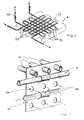
- the exchanger heat 4 includes a first circuit, formed of tubes 20, in which the compressed gas and a second circuit circulates, formed of tubes 21, in which the refrigerant circulates.
- the tubes 20 are parallel to each other and the tubes 21 are also parallel to each other.
- the tubes 20 and 21 are globally perpendicular.
- the circuits formed by the tubes 20 and 21 are arranged in an intermediary agent 23 who surrounds them and ensures the transfer between the tubes 20 and the tubes 21, that is to say between the two circuits.
- This intermediary agent is chosen in function of its thermal inertia to prevent variations of the flow of gas passing through the tubes 20 do not lead, in the event of low gas consumption, over-cooling of it, which would result in the formation ice in exchanger 4 and its possible destruction.
- the intermediate agent can be placed in the exchanger 4, which is provided with a closed enclosure, when the tubes 20 and 21 are in place. It can be a liquid, a solid, monobloc to particulate, gas or gel. He can be formed of a simple body, or of a mixture of those envisaged above.
- This intermediate agent can be produced on the basis of metal, plastic or any other suitable material, such as brine, sand, etc.
- spacer plates 25 are arranged in the exchanger heat 4 and keep tubes 20 and 21 at bay to avoid direct transfer of calories or frigories from one tube circuit to another.
- These plates 25, one of which is shown in Figure 3, are arranged perpendicularly to the tubes of a circuit, for example the tubes 20, and in parallel to the tubes of the other circuit, for example the tubes 21.
- the tubes 20 and 21 are shown only in the upper part of the plate 25.
- Each plate 25 comprises orifices 25a for the passage of the tubes to which it is perpendicular and depressions 25 b forming sleeve-supports for the tubes 21 to which it is parallel.
- the orifices 25 a have a shape similar to the outer surface of the tubes 20. If the tubes 20 are circular, which is generally the case, it can be provided that the orifices 25a are also circular.
- the depressions 25 b each form one half of a sleeve supporting the tubes 21. On a section corresponding to the path of a tube 21 along the plate 25, at least two depressions 25 b follow one another, being arranged on both sides and d 'other of the main surface of the plate 25.
- the tube 21 shown in Figure 3 passes in front of a first depression 25 b located on the left of Figure 3, then behind a second depression 25 b located in the central part and finally in front of a third depression 25 b located on the right.
- a sleeve is formed by the succession of two depressions because their cooperation limits the movements of the tube 21 both forward and backward of the plate 25 in the position of FIG. 3.
- the number of depressions arranged, on the path of a tube 21, in the width of the plate 25, is greater than or equal to two.
- Several sleeves can be formed over the width of the plate 25 by a succession of depressions alternately located on either side of the main surface of the plate 25.
- the geometry of the depressions 25 b is defined as a function of that of the tubes 21 so that they substantially match the external shape of the latter.
- the plates 25 are easy to manufacture, for example at using a press, and allow to perform the function spacing sought at low cost. Indeed, no room should only be reported on plates 25 to allow them to support two networks of tubes which are perpendicular between them.
Landscapes
- Engineering & Computer Science (AREA)
- Physics & Mathematics (AREA)
- Thermal Sciences (AREA)
- Chemical & Material Sciences (AREA)
- Mechanical Engineering (AREA)
- General Engineering & Computer Science (AREA)
- Chemical Kinetics & Catalysis (AREA)
- Analytical Chemistry (AREA)
- General Chemical & Material Sciences (AREA)
- Oil, Petroleum & Natural Gas (AREA)
- Drying Of Gases (AREA)
Applications Claiming Priority (2)
| Application Number | Priority Date | Filing Date | Title |
|---|---|---|---|
| FR9611044 | 1996-09-05 | ||
| FR9611044A FR2752920B1 (fr) | 1996-09-05 | 1996-09-05 | Centrale de compression et de sechage de gaz |
Publications (2)
| Publication Number | Publication Date |
|---|---|
| EP0827773A1 true EP0827773A1 (de) | 1998-03-11 |
| EP0827773B1 EP0827773B1 (de) | 2003-11-19 |
Family
ID=9495621
Family Applications (1)
| Application Number | Title | Priority Date | Filing Date |
|---|---|---|---|
| EP19970420159 Expired - Lifetime EP0827773B1 (de) | 1996-09-05 | 1997-09-03 | Kompressions- und Gastrocknungszentrale |
Country Status (3)
| Country | Link |
|---|---|
| EP (1) | EP0827773B1 (de) |
| DE (1) | DE69726230D1 (de) |
| FR (1) | FR2752920B1 (de) |
Cited By (1)
| Publication number | Priority date | Publication date | Assignee | Title |
|---|---|---|---|---|
| EP1093841A1 (de) * | 1999-10-21 | 2001-04-25 | Claude Restle | Stoff- und Wärmeaustauscher |
Citations (8)
| Publication number | Priority date | Publication date | Assignee | Title |
|---|---|---|---|---|
| FR1172210A (fr) * | 1956-02-07 | 1959-02-06 | Philips Nv | Procédé et dispositif pour chauffer et refroidir périodiquement un échangeur de chaleur |
| US4166449A (en) * | 1975-04-28 | 1979-09-04 | Depew Walter L | Heat storage vault |
| GB2074305A (en) * | 1980-04-19 | 1981-10-28 | Applegate G | Heat Exchangers |
| EP0067044A2 (de) * | 1981-06-05 | 1982-12-15 | Russell Finex Limited | Wärmeaustauscher |
| EP0473513A1 (de) * | 1990-08-28 | 1992-03-04 | Gec Alsthom Sa | Aggregat zur Klimatisierung und Erzeugung von Druckluft für ein Schienentriebfahrzeug |
| DE9401979U1 (de) * | 1994-02-07 | 1994-11-03 | Enigk, Hans-Joachim, Dipl.-Ing., 04860 Torgau | Heizkörper für Wohnräume o.dgl. |
| WO1995003103A1 (de) * | 1993-07-26 | 1995-02-02 | Hiross International Corporation B.V. | Einrichtung zur verringerung des feuchtigkeitsgehalts eines gasförmigen mediums |
| DE4342598A1 (de) * | 1993-12-14 | 1995-06-22 | Sabroe Gmbh Druckluft Und Gast | Vorrichtung zur Trocknung von Druckluft |
-
1996
- 1996-09-05 FR FR9611044A patent/FR2752920B1/fr not_active Expired - Fee Related
-
1997
- 1997-09-03 EP EP19970420159 patent/EP0827773B1/de not_active Expired - Lifetime
- 1997-09-03 DE DE69726230T patent/DE69726230D1/de not_active Expired - Lifetime
Patent Citations (8)
| Publication number | Priority date | Publication date | Assignee | Title |
|---|---|---|---|---|
| FR1172210A (fr) * | 1956-02-07 | 1959-02-06 | Philips Nv | Procédé et dispositif pour chauffer et refroidir périodiquement un échangeur de chaleur |
| US4166449A (en) * | 1975-04-28 | 1979-09-04 | Depew Walter L | Heat storage vault |
| GB2074305A (en) * | 1980-04-19 | 1981-10-28 | Applegate G | Heat Exchangers |
| EP0067044A2 (de) * | 1981-06-05 | 1982-12-15 | Russell Finex Limited | Wärmeaustauscher |
| EP0473513A1 (de) * | 1990-08-28 | 1992-03-04 | Gec Alsthom Sa | Aggregat zur Klimatisierung und Erzeugung von Druckluft für ein Schienentriebfahrzeug |
| WO1995003103A1 (de) * | 1993-07-26 | 1995-02-02 | Hiross International Corporation B.V. | Einrichtung zur verringerung des feuchtigkeitsgehalts eines gasförmigen mediums |
| DE4342598A1 (de) * | 1993-12-14 | 1995-06-22 | Sabroe Gmbh Druckluft Und Gast | Vorrichtung zur Trocknung von Druckluft |
| DE9401979U1 (de) * | 1994-02-07 | 1994-11-03 | Enigk, Hans-Joachim, Dipl.-Ing., 04860 Torgau | Heizkörper für Wohnräume o.dgl. |
Cited By (1)
| Publication number | Priority date | Publication date | Assignee | Title |
|---|---|---|---|---|
| EP1093841A1 (de) * | 1999-10-21 | 2001-04-25 | Claude Restle | Stoff- und Wärmeaustauscher |
Also Published As
| Publication number | Publication date |
|---|---|
| FR2752920A1 (fr) | 1998-03-06 |
| EP0827773B1 (de) | 2003-11-19 |
| DE69726230D1 (de) | 2003-12-24 |
| FR2752920B1 (fr) | 1998-10-09 |
Similar Documents
| Publication | Publication Date | Title |
|---|---|---|
| FR2468088A1 (fr) | Appareil d'echange de chaleur ayant deux circuits de refrigeration et son procede d'exploitation | |
| FR2715211A1 (fr) | Procédé d'exploitation d'un système de réfrigération et système de réfrigération fonctionnant selon ce procédé. | |
| FR2715212A1 (fr) | Procédé et appareil d'exploitation d'un système de réfrigération, caractérisés par une régulation du liquide de refroidissement du moteur. | |
| FR2715213A1 (fr) | Procédé et appareil d'exploitation d'un système de réfrigération, caractérisés par une régulation de la pression maximale de fonctionnement. | |
| FR2899960A1 (fr) | Dispositif de recuperation de chaleur d'echappement | |
| EP2633245B1 (de) | Wärmeaustauschsystem zwischen zuluft und abluft und verfahren mit einem solchen system | |
| CA2679351A1 (fr) | Dispositif et procede de refroidissement de boissons | |
| WO2016012501A1 (fr) | Installation de production de froid comprenant des moyens de condensation a la fois par air et par eau, ainsi que son procede de mise en œuvre | |
| FR2894014A1 (fr) | Unite solaire de production frigorifique pour installation de climatisation et procede de controle correspondant | |
| EP0827773B1 (de) | Kompressions- und Gastrocknungszentrale | |
| CA2088704A1 (fr) | Procede d'alimentation en frigories d'une enceinte refrigeree ouverte pour l'exposition et la vente en libre service de produits frais | |
| EP2739918B1 (de) | System und verfahren zur optimierung des betriebs eines wärmepumpensystems | |
| WO2015162344A1 (fr) | Moyens d' échange thermique liquide/gaz, notamment eau/air, et système de production d'eau à partir de l' humidité de l'air comprenant de tels moyens | |
| FR2493972A1 (fr) | Procede de degivrage d'appareils de traitement d'air a pompe a chaleur et dispositif pour l'execution du procede | |
| FR2460458A1 (fr) | Pompe a chaleur et procede pour son degivrage | |
| FR2505465A1 (fr) | Systeme de degivrage ameliore pour pompes a chaleur a cycle reversible | |
| EP3039353B1 (de) | System und verfahren zur lüftung und klimatisierung | |
| FR2466728A1 (fr) | Dispositif de deshumidification d'un fluide gazeux pour le sechage en cellule de materiaux ou produits | |
| FR2505999A1 (fr) | Procede et appareil de condensation de vapeur pour extraire de facon continue un condensat a partir d'un courant de gaz comprime | |
| FR2901015A1 (fr) | Batterie a air surchauffe dans le cadre d'un groupe frigorifique, pompe a chaleur. | |
| FR2524623A1 (fr) | Procede et dispositif pour le prerefroidissement d'une installation de production d'air a basse temperature | |
| WO2015104330A1 (fr) | Pompe à chaleur produisant du froid | |
| EP2461108B1 (de) | Wandheizvorrichtung, Ausstattung zum Aufheizen einer Flüssigkeit, Heizanlage eines Lokals und Anpassungsverfahren einer Wandheizvorrichtung | |
| FR2494822A1 (fr) | Procede de degivr | |
| FR2864609A1 (fr) | Installation thermique a configuration multiple, et echangeur adapte a cette installation. |
Legal Events
| Date | Code | Title | Description |
|---|---|---|---|
| PUAI | Public reference made under article 153(3) epc to a published international application that has entered the european phase |
Free format text: ORIGINAL CODE: 0009012 |
|
| AK | Designated contracting states |
Kind code of ref document: A1 Designated state(s): BE DE ES FR GB IT |
|
| 17P | Request for examination filed |
Effective date: 19980828 |
|
| AKX | Designation fees paid |
Free format text: BE DE ES FR GB IT |
|
| RBV | Designated contracting states (corrected) |
Designated state(s): BE DE ES FR GB IT |
|
| 17Q | First examination report despatched |
Effective date: 20020819 |
|
| GRAH | Despatch of communication of intention to grant a patent |
Free format text: ORIGINAL CODE: EPIDOS IGRA |
|
| GRAS | Grant fee paid |
Free format text: ORIGINAL CODE: EPIDOSNIGR3 |
|
| GRAA | (expected) grant |
Free format text: ORIGINAL CODE: 0009210 |
|
| AK | Designated contracting states |
Kind code of ref document: B1 Designated state(s): BE DE ES FR GB IT |
|
| PG25 | Lapsed in a contracting state [announced via postgrant information from national office to epo] |
Ref country code: IT Free format text: LAPSE BECAUSE OF FAILURE TO SUBMIT A TRANSLATION OF THE DESCRIPTION OR TO PAY THE FEE WITHIN THE PRESCRIBED TIME-LIMIT;WARNING: LAPSES OF ITALIAN PATENTS WITH EFFECTIVE DATE BEFORE 2007 MAY HAVE OCCURRED AT ANY TIME BEFORE 2007. THE CORRECT EFFECTIVE DATE MAY BE DIFFERENT FROM THE ONE RECORDED. Effective date: 20031119 Ref country code: GB Free format text: LAPSE BECAUSE OF FAILURE TO SUBMIT A TRANSLATION OF THE DESCRIPTION OR TO PAY THE FEE WITHIN THE PRESCRIBED TIME-LIMIT Effective date: 20031119 |
|
| REG | Reference to a national code |
Ref country code: GB Ref legal event code: FG4D Free format text: NOT ENGLISH |
|
| REF | Corresponds to: |
Ref document number: 69726230 Country of ref document: DE Date of ref document: 20031224 Kind code of ref document: P |
|
| PG25 | Lapsed in a contracting state [announced via postgrant information from national office to epo] |
Ref country code: DE Free format text: LAPSE BECAUSE OF FAILURE TO SUBMIT A TRANSLATION OF THE DESCRIPTION OR TO PAY THE FEE WITHIN THE PRESCRIBED TIME-LIMIT Effective date: 20040220 |
|
| PG25 | Lapsed in a contracting state [announced via postgrant information from national office to epo] |
Ref country code: ES Free format text: LAPSE BECAUSE OF FAILURE TO SUBMIT A TRANSLATION OF THE DESCRIPTION OR TO PAY THE FEE WITHIN THE PRESCRIBED TIME-LIMIT Effective date: 20040302 |
|
| GBV | Gb: ep patent (uk) treated as always having been void in accordance with gb section 77(7)/1977 [no translation filed] |
Effective date: 20031119 |
|
| PLBE | No opposition filed within time limit |
Free format text: ORIGINAL CODE: 0009261 |
|
| STAA | Information on the status of an ep patent application or granted ep patent |
Free format text: STATUS: NO OPPOSITION FILED WITHIN TIME LIMIT |
|
| 26N | No opposition filed |
Effective date: 20040820 |
|
| PGFP | Annual fee paid to national office [announced via postgrant information from national office to epo] |
Ref country code: BE Payment date: 20041208 Year of fee payment: 8 |
|
| PG25 | Lapsed in a contracting state [announced via postgrant information from national office to epo] |
Ref country code: BE Free format text: LAPSE BECAUSE OF NON-PAYMENT OF DUE FEES Effective date: 20050930 |
|
| BERE | Be: lapsed |
Owner name: *CTA Effective date: 20050930 |
|
| REG | Reference to a national code |
Ref country code: FR Ref legal event code: PLFP Year of fee payment: 20 |
|
| PGFP | Annual fee paid to national office [announced via postgrant information from national office to epo] |
Ref country code: FR Payment date: 20160928 Year of fee payment: 20 |