EP0827794A2 - Dispositif et procédé de coulée sous pression - Google Patents
Dispositif et procédé de coulée sous pression Download PDFInfo
- Publication number
- EP0827794A2 EP0827794A2 EP97115171A EP97115171A EP0827794A2 EP 0827794 A2 EP0827794 A2 EP 0827794A2 EP 97115171 A EP97115171 A EP 97115171A EP 97115171 A EP97115171 A EP 97115171A EP 0827794 A2 EP0827794 A2 EP 0827794A2
- Authority
- EP
- European Patent Office
- Prior art keywords
- die casting
- die
- piston
- control
- suction
- Prior art date
- Legal status (The legal status is an assumption and is not a legal conclusion. Google has not performed a legal analysis and makes no representation as to the accuracy of the status listed.)
- Granted
Links
Images


Classifications
-
- B—PERFORMING OPERATIONS; TRANSPORTING
- B22—CASTING; POWDER METALLURGY
- B22D—CASTING OF METALS; CASTING OF OTHER SUBSTANCES BY THE SAME PROCESSES OR DEVICES
- B22D17/00—Pressure die casting or injection die casting, i.e. casting in which the metal is forced into a mould under high pressure
- B22D17/20—Accessories: Details
- B22D17/32—Controlling equipment
-
- B—PERFORMING OPERATIONS; TRANSPORTING
- B22—CASTING; POWDER METALLURGY
- B22D—CASTING OF METALS; CASTING OF OTHER SUBSTANCES BY THE SAME PROCESSES OR DEVICES
- B22D17/00—Pressure die casting or injection die casting, i.e. casting in which the metal is forced into a mould under high pressure
- B22D17/08—Cold chamber machines, i.e. with unheated press chamber into which molten metal is ladled
- B22D17/10—Cold chamber machines, i.e. with unheated press chamber into which molten metal is ladled with horizontal press motion
-
- B—PERFORMING OPERATIONS; TRANSPORTING
- B22—CASTING; POWDER METALLURGY
- B22D—CASTING OF METALS; CASTING OF OTHER SUBSTANCES BY THE SAME PROCESSES OR DEVICES
- B22D17/00—Pressure die casting or injection die casting, i.e. casting in which the metal is forced into a mould under high pressure
- B22D17/14—Machines with evacuated die cavity
Definitions
- the invention relates to a die casting device comprising a die, a plunger to Pressing a casting material into the die and a gas extraction device with a vacuum generating device for extracting gas from the die.
- the invention further relates to a die casting method, in which a casting material by means of a press-in piston is pressed into a die and from the Die casting mold by means of a gas extraction device Vacuum gas is sucked off.
- Regulation of a vacuum in a die casting machine is the negative pressure on the mold over a Control valve controlled so that the vacuum in the die casting mold according to an adjustable curve with at least two periods is regulated.
- the negative pressure is generated by a vacuum pump connected to a Vacuum tank is connected via a switching valve is connected to the die.
- a die casting process is known from DE 36 05 529 C2, with an evacuation of the die there is a delay.
- the invention has for its object a die casting device with the features mentioned above to improve such that optimal gas extraction is reached during a casting process.
- This task is performed by the die casting device the features mentioned in the introduction solved that the injection piston with the vacuum generating device is coupled to the vacuum generation through the negative pressure generating device Taxes.
- the device according to the invention Since the vacuum generation when the injection piston is at a standstill automatically in the device according to the invention stops, no vacuum valve has to be provided as in the devices known from the prior art, that turns off the vacuum. As a result, the device according to the invention is absent also the complicated process of adjusting the valve closure to the system because the switch-off point of a vacuum valve from a number of difficult to determine Parameters such as fluctuations in the amount of casting material and also the own shutdown time of the vacuum valve, depends.
- press-in piston mechanically with the vacuum generating device is coupled. In this way, the movement of the press-in piston directly to generate the negative pressure insert in the vacuum generator.
- the vacuum generating device comprises at least one suction cylinder, which has a sliding suction piston for generating negative pressure has, the suction piston to the Injection piston is coupled.
- This allows one secondary vacuum system provided for the out devices and methods known from the prior art must be provided. The invention This makes the device clearer, inexpensive and easy to service.
- the press-in piston with the suction piston of the suction cylinder is connected so that the movement of the injection piston the displacement of the suction piston controls in the suction cylinder for generating negative pressure.
- a suction cylinder advantageously has one or more Vent valves on. This allows the Bleed the suction cylinder, especially for a light one Displaceability of the suction piston and traceability to ensure the suction piston in its initial position.
- a coupling of the injection piston to the suction piston leaves themselves in a structurally particularly simple way achieve that a piston rod of the press-in piston rigidly connected to a piston rod of the suction piston is.
- Die casting device is provided that the suction cylinder or cylinders on a guide device of the injection piston. That way the suction cylinders can be installed in a fixed position and it is secured, that the movement of the plunger on the movement of the suction piston is transferred without tilting.
- This also allows an existing die casting device with a suction cylinder as a vacuum generating device retrofit to the already existing die casting machine according to the gas extraction to control the method according to the invention.
- suction cylinder or cylinders in one Guide device of the press-in piston integrated. This is particularly advantageous if several suction cylinders are provided in this way for coupling to provide the suction piston to the injection piston.
- the die casting device has several Includes suction cylinders, which are related symmetrically arranged on a displacement guide of the press-in piston are. This enables a clean parallel Alignment of the respective displacements of the suction pistons and the press-in piston.
- a variant of an embodiment includes the die casting device according to the invention two suction cylinders. This can be done in a structurally simple manner a sufficiently large negative pressure generation by the Reach vacuum generating device.
- the gas extraction device has a control or regulating valve, by means of which a negative pressure application of the die is controllable or regulatable.
- a negative pressure application of the die is controllable or regulatable.
- the suction cylinders are chosen in such a size that they have a provide greater negative pressure than it actually does is needed.
- control or regulating valve is designed as a proportional valve, so that the air supply is easy can be controlled.
- At least one for gas extraction Separation device downstream of the die is, by which it is possible to prevent casting material in Gas extraction lines arrives. This makes it special not required the gas extraction lines to have to clean after each die casting process, so that Dead times of the die casting device are reduced.
- a filter can be used as the separation device be provided that the flow of casting material in gas suction lines downstream of the filter prevented.
- Particularly favorable casting results can be achieved if a washboard device as a separation device which flow inhibition elements are provided for casting material flowing into the washboard device having. In this way it can be achieved that the die during the press-in or shooting process of the injection piston can suck off gas and at Reaching a fill of the die casting flow of casting material in corresponding gas extraction lines is preventable.
- the Flow inhibiting elements related to the direction of flow, in the casting material flows into the separation device in are arranged essentially transversely. Thereby the Casting material flow velocity components that are perpendicular to the original flow direction, so reduce the resulting flow rate.
- the separation device has a control unit through which the admission of the Separation device with casting material can be monitored.
- This can be, for example, a level meter or act as a temperature sensor.
- this control unit is then, in particular, reaching the end of the casting process can be monitored, so that the negative pressure at the end of the pouring process on simple Way.
- the pressure sensor is in close to an opening of the die for suction of gas is arranged so that the pressure is essentially during the entire injection process of casting material can be monitored in the die.
- control and regulation unit with the pressure sensor in the die is connected and especially if the by the Pressure sensor measured pressure a controlled variable for regulating of negative pressure generation.
- control and Control unit with the control unit of the separation device and if that is connected by the Control unit of the separation device measured exposure with cast material is a standard. Thereby can be especially at the end of the casting process optimally monitor the gas extraction and, for example prevent when the die casting mold with casting material is filled, by means of the pouring suction device is sucked out of the die.
- control unit with the Control or regulating valve is connected, in particular a valve position of the control or regulating valve is a manipulated variable.
- pressurizing the die using a vacuum tank to apply a vacuum by means of the vacuum generating device is switchable.
- the negative pressure can be applied adapt optimally. For example can in an initial phase of the pressing process Cast material into the die using the vacuum tank applied with a constant negative pressure and at an appropriate time will apply to the negative pressure by the vacuum generating device switched, then the generation of negative pressure controlled by the injection piston and thus dependent from his state of motion.
- the die casting mold by the vacuum generating device independent via at least two connections can be acted upon with negative pressure. This leaves extract gas from the die at several points. This can be advantageous in certain configurations of the mold volume for special die-cast parts.
- each a suction cylinder is provided.
- the respective Suction cylinder is then connected to the associated Aspirated gas from the die.
- a control or regulating valve for the independent application of negative pressure the die casting mold over at least two connections are provided.
- the invention is also based on the object Die casting process with the features mentioned above to improve so that high quality in the manufactured Die casting is achievable.
- the die-casting method according to the invention already has this in connection with the die casting device according to the invention advantages mentioned.
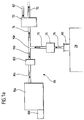
- An embodiment of a die casting device according to the invention which as a whole in FIG. 1 with 10 is referred to, comprises a stationary frame 12.
- the frame 12 are rigidly connected to it a first Holding element 14 and a second holding element 16 mounted.
- first holding element 14 and the second Holding element 16 are horizontally lying movement rails 18 arranged on which a die holding element 20 slidable in the horizontal direction is.
- the displacement movement is controlled by a hydraulic Drive 22 via between the first holding element 14 and the die holding element 20 arranged Toggle lever 24 causes.
- One is rigidly connected to the second holding element 16 immovable mold half 26 of a die casting mold 28.
- a movable mold half 30 of the die 28 is through the movable die holding element 20 held.
- a casting position 32 is the die holding element 20 shifted relative to the first holding element 14 so that opposite surfaces of the movable Mold half 30 and the immovable mold half 26 of the Die casting mold 28 abut one another to perform a die casting operation to enable.
- the toggle lever 24 By means of the toggle lever 24 the pouring position 32 secured.
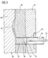
- a casting chamber 36 opens into the mold volume 34 which is a casting material 37, for example a metallic one Melt, the mold volume 34 can be fed.
- the Casting chamber 36 is, for example, a cylindrical one Tube 38 formed by the immovable Mold half 26 and the second holding element 16 therethrough extends.
- the cylindrical tube 38 has one on an upper one Side arranged inlet opening 40 through which a liquid casting material can be filled into the casting chamber 36 is.
- the casting material fed through the inlet opening 40 is displaceable by a in the cylindrical tube 38 Injection piston 42 via the casting chamber 36 fed to the mold volume 34.
- the press-in piston 42 a piston head 44 which is rigid with a linearly guided piston rod 46 is connected.
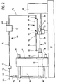
- the piston rod 46 is in a guide device 48 for linear guidance of the press-in piston 42 in the cylindrical Pipe 38 stored ( Figure 1, 2).
- the guide device 48 is held rigidly on a holder 50, which is rigidly mounted on the frame 12.
- the guide device 48 can be designed in particular as a guide and as a drive device, through which the piston rod 46 by means of a drive 52, for example a hydraulic drive, is displaceable is.
- the guide device 48 has one Path encoder 54, by means of which can be determined Travel the piston rod 46 and thus the piston head 44 covered from a starting position and for example through a movable in a guide 55 Ruler 57 is formed, the ruler 57 then the plunger 42 is connected ( Figure 4).
- Die casting device is on the guide device 48 a suction cylinder 56 is mounted (FIG 1, Figure 2).
- a cylinder axis of the suction cylinder 56 is parallel to the piston rod 46 of the press-in piston 42 aligned.
- the suction cylinder comprises a suction piston 58 with a suction piston head 59, which is in the suction cylinder 56 displaceable by means of a piston rod 60 is.
- the piston rod 60 is a form-locking element 62 with the piston rod 46 of the press-in piston 42 connected so that the linear movement of the piston rod 46, driven by the drive 52, on the suction piston 58 is transmitted.
- the suction cylinder 56 has a near its end, which is facing the die 28, one or several vent valves 63.
- the suction cylinder 56 with the suction piston 58 forms one Vacuum generating device 64 of a gas extraction device 66, by means of the gas from the mold volume 34 when molding material is pressed into the mold volume 34 is extractable.
- the suction cylinder 56 has one surface of the suction piston head 59 opposite end Suction opening 68 to which a gas suction line 70 connected.
- the gas extraction line 70 leads to a control or regulating valve 72, which is in particular can be a proportional valve, and another leads from the control or regulating valve 72 Gas extraction line 74 to a first output of a Two-way valve 150. From a second outlet this Two-way valve carries another gas extraction line 152 to an optional vacuum tank 154, which is connected to a vacuum pump 156 is.
- Fig. 1a leads the gas extraction line 74 from a first outlet a branch 158 to the control or regulating valve 72.
- Another gas extraction line 160 leads from a second exit of branch 158 to an entrance of check valve 162.
- From an exit of the check valve 162 leads a further gas extraction line 164 to the vacuum tank 154 with the vacuum pump 156.
- Die von the gas suction line 75 coming into the filter 76 opens into an entrance of junction 158.
- the connection of the Filter 76 with the die is as described above.
- the filter 76 serves to prevent intrusion of To prevent pouring material into the gas extraction line 74.
- control or regulating valve 72 Via the control or regulating valve 72 is via a Air supply 82 in the gas extraction line 74 and / or Air can be introduced into the gas extraction line 70 in order to in this way by the vacuum generating device 64 generated negative pressure on the respective need to make customizable in the die 28.
- control valve 72 and the Gas extraction line 70 are arranged stationary and the terminal board 80 with the movable mold half 30th connected is. It must then be provided that the Gas extraction lines 78 and 74 are flexible are to reach the pouring position 32 or a To allow opening of the die 28.
- a pressure sensor 84 arranged by means of a gas pressure can be determined.
- the pressure sensor 84 is near the connection board 80 arranged to gas evacuation through the gas suction device 66 to essentially complete Filling the mold volume 34 with casting material controllable or to make it controllable.
- the pressure sensor 84 outputs its sensor signals to a Control and regulation unit 86, with which over the control or regulating valve 72 the negative pressure application the die casting mold 28 by means of the gas extraction device 66 can be controlled or regulated. Is to the control or regulating valve 72 with the control and Control unit 86 connected to an air supply through the air supply 82 into the gas extraction line 74 and / or 70 to control or regulate.
- the two-way valve 150 (FIG. 1) or the check valve 162 (Fig. 1a) is also with the control unit 86 connected and controllable by this.
- the filter 76 has a control unit (in the Figure 1 not shown), the exposure of the filter 76 determined with casting material. It can happen For example, temperature sensors are one Measure the level in the filter. The signal found is sent to the control and regulation unit 86 passed on. The control unit regulates this by means of the pressure sensor 84 and the control unit of the filter 76 the gas pressure in the die 28 and the casting material application of the filter 76.
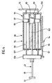
- FIG 4 includes the die casting device according to the invention a guide device 88 with a Press-in piston guide 90, in which a guide element 92 of the press-in piston 42 is guided linearly.
- a plurality of suction cylinders are in the guide device 88 94 integrated, which refers to the management direction of the Press-in piston 42 arranged symmetrically to one another are.
- the respective suction cylinders 94 are special constructed the same way and have the same dimensions on.
- each suction cylinder 94 there is a suction piston 96 with a suction piston head 97, held by a piston rod 98, slidably mounted.
- the piston rods 98 of the respective suction piston 96 are mutually a connecting element 100 rigidly connected, so that all suction pistons 96 in the respective suction cylinders 94 are moved at the same time and the same movement carry out.
- the connecting element 100 is rigid connected to a guide rod 102 of the press-in piston 42, whereby by means of the guide rod 102 and the Guide element 92 of the press-in piston 42 is guided. This causes a displacement and movement of the injection piston 42, caused by a drive (in the figure not shown), on the respective suction pistons 96 the associated suction cylinder 94 transmitted.
- the suction cylinder 94 have on one surface of the Suction piston heads 97 opposite ends each Suction openings 104 on that with the gas extraction line 70 are connected. This allows for several suction cylinders 94 at the same time by the movement of the injection piston 84 create a negative pressure through which the die 28 can act. Nearby the ends of the suction cylinders 94 which are the suction openings 104 are opposite, vent valves 107 to Vent the suction cylinder 94 provided.
- the gas extraction device 66 so is formed that gas in two or more places the die 28 can be sucked out of the mold volume 34 is.
- FIG. 4a leads from a suction opening 200 Suction cylinder 202 a gas extraction line 204 to one Control valve 206, which a Has air supply 208 and that with the control and Control unit 86 is connected.
- Another gas suction line leads from the control and regulating valve 206 210 to a filter 212, one of which further gas extraction line 214 to a connection board 216 leads over which the die 28 with negative pressure is acted upon.
- a gas extraction line 228 leads to a branch 230, from one of which a generation point a gas extraction line 232 to another filter 234 leads.
- Another gas extraction line leads from there 236 to another connection board 238.
- Das Terminal board 238 is in another place Die casting mold 28 arranged as the terminal board 216.
- junction point of junction 230 Another gas extraction line 240 to another filter 250 and from there leads another gas extraction line 252 to one arranged on the die 28 Terminal board 254.
- the die can be made in different ways Position - controlled or regulated by the tax or Control valve 206 via the terminal board 216 and controlled or regulated via the control or regulating valve 224 over the connection boards 238 and 254 - with negative pressure act and thereby can be with certain Types of die-cast parts a better casting result achieve as if gas extraction only on one Place of the die would be provided.
- the variant is in particular an independent pressurization across the terminal board 216 opposite the connection boards 238 and 254 possible.
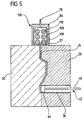
- Terminal board 80 includes a washboard device 106.
- the washboard device 106 acts as a separation device and can thereby cooperate with the filter 76 or replace it.
- An entrance opening 108 of the washboard device is with the mold volume 34 connected so that casting material 37 from the mold volume 34 flow into the washboard device 106 can when the mold volume 34 is filled with casting material is.
- In the washboard device 106 are arranged vertically Flow inhibiting elements 110 arranged, the Cast material flow through washboard device 106 inhibit.
- the Washboard device 106 includes a control unit 109, through which the casting material is applied to the Washboard device can be determined.
- the die casting device works as follows: By means of the hydraulic drive 22 and the toggle lever 24, the movable mold half 30 of the die casting mold 28 is brought into the casting position 32, so that the mold volume 34 has the shape of the casting to be cast.
- the injection piston is at the beginning of the die casting process 42 with its piston head 44 so that over the inlet opening 40 of the casting chamber 36 casting material, such as a molten metal, feedable is.
- the suction piston head 59 is in this initial position of the press-in piston 42 in the vicinity of the suction opening 68, to increase the volume of the volume between one Surface of the suction piston head 59 and the opposite End of the suction cylinder 56 when pressing in casting material to allow in the die casting mold 28.
- the press-in process of casting material through the plunger 42 in the mold volume 34 comprises several phases.
- a first phase the press-in piston with a Moving speed from about 0.1 to 0.2 m / s.
- a second phase is the speed of the injection piston increased to approximately 1 m / s to 6 m / s.
- Means of the displacement sensor 54 which is the linear displacement of the press-in piston 42 is monitored in the casting chamber 36 determines when the speed of the plunger 42 is to be increased.
- the method provides that in a Initial phase of the press-in or shot movement of the press-in piston 42 the mold volume 34 by means of the vacuum tank 154 by one generated by the vacuum pump 156 Vacuum is applied, which is essentially independent of the movement of the press-in piston 42 is.
- the two-way valve 150 is switched that the gas path from the gas extraction line 75 in the Gas extraction line 152 is open and the gas path is off of the gas suction line 75 into the gas suction line 74 is blocked (see FIG. 1).
- this in this embodiment of the invention Procedure opened in the initial phase to gas evacuation via the gas extraction lines 75, 160 and 164 to enable.
- the two-way valve 150 is on a gas exhaust path via the gas extraction lines 74 and 75 when the passage from the gas extraction line is blocked 75 to 152 ( Figure 1) switched or the check valve 162 ( Figure 1a) is closed so that the mold volume 34 with that generated by the vacuum generating device 64 Vacuum is applied.
- Switching the two-way valve 150 or locking of the check valve 162 is by the control and Control unit 86 controlled.
- suction piston 58 Since the suction piston 58 is rigidly coupled to the press-in piston 42 the movement of the injection piston becomes proportional transferred to the suction piston 58. Especially there is a change in the speed of the injection piston 42 directly to a proportional change in speed of the suction piston 58.
- the die casting method according to the invention can be used therefore increase the quality of die cast parts, as annoying Pressures of gas in the mold volume 34 are very high can be compensated quickly.
- the plunger 42 stops when the mold volume 34 is filled, the gas extraction through the gas suction device 66 essentially stopped. It is prevented by the gas extraction device Casting material from the mold volume 34 is pulled out.
- the vacuum generation by the vacuum generation device 64 essentially depends on the speed of the press-in piston 42 and the cross-sectional area of the suction cylinder 56 or the suction cylinder 94, where the essential size is the volume change of volume between one end of the suction piston head 59 and the opposite end of the suction cylinder 56 (or between the ends of the suction piston heads 97 and the ends of the suction cylinders 94).
- the control or regulating valve 72 is provided.
- Air supply via the air supply 82 into the gas extraction device 66 the mold volume 34 with a Apply smaller vacuum than that from the vacuum generating device 64 is delivered.
- This enables a structurally inexpensive adjustment the die casting device according to the invention and the invention Die casting process to a variety of configurations of mold volumes corresponding to one Numerous configurations of die-cast parts since then also with different die-cast parts different mold volumes 34 of the suction cylinders 56 or the suction cylinder 94 cannot be replaced must, but just a control or regulation the pressurization of the die 28 by the Control or regulating valve 72 takes place.
- the Pressurizing the mold volume 34 via the control and regulating unit 86 during a press-in process is regulated.
- the control and Control unit 86 as controlled variables by the Pressure sensor 84 measured pressure of the gas in the mold volume 34 and the pouring of the separating device 76 or 106.
- the control and regulation unit 86 uses this to determine the optimal pressurization the die 28.
- Control and regulation unit 86 calibration data by means of which the manipulated variable, i.e. the Air supply through the air supply 82 via the control or Control valve 72 in the gas extraction lines 70 and / or 74, is optimally adapted to the respective Mold volume 34 at predetermined press-in speeds of the press-in piston 42 and for a given size of the suction cylinder 56 or the suction cylinder 94.
- the pressure sensor 84 can then be pressed in Determine deviations from the optimal pressure values, and leaves via the control or regulating valve 72 itself, caused by the control and regulation unit 86, the pressurization of these deviations optimize.
- control device of the separation device filter 76 or washboard device 1066
- a casting material application reports the control or regulating valve 72 fully opens to the negative pressure in the Gas extraction device 66 to end.
- the Position sensor 54 signals to the control and regulation unit 86 supplies.
- a check valve or Slider 112 which or for example in the control and regulating valve 72 is integrated and by means of which the connection to the vacuum generating device 64 can be closed, the negative pressure can be applied of the mold volume 34 by means of Only switch on the control and regulating unit 86 when the plunger head 44 over the inlet port 40 is shifted to air intake through the inlet opening 40 to avoid.
Landscapes
- Engineering & Computer Science (AREA)
- Mechanical Engineering (AREA)
- Moulds For Moulding Plastics Or The Like (AREA)
- Injection Moulding Of Plastics Or The Like (AREA)
- Encapsulation Of And Coatings For Semiconductor Or Solid State Devices (AREA)
Applications Claiming Priority (2)
| Application Number | Priority Date | Filing Date | Title |
|---|---|---|---|
| DE19635996 | 1996-09-05 | ||
| DE19635996 | 1996-09-05 |
Publications (3)
| Publication Number | Publication Date |
|---|---|
| EP0827794A2 true EP0827794A2 (fr) | 1998-03-11 |
| EP0827794A3 EP0827794A3 (fr) | 1999-01-13 |
| EP0827794B1 EP0827794B1 (fr) | 2001-04-18 |
Family
ID=7804680
Family Applications (1)
| Application Number | Title | Priority Date | Filing Date |
|---|---|---|---|
| EP97115171A Expired - Lifetime EP0827794B1 (fr) | 1996-09-05 | 1997-09-02 | Dispositif et procédé de coulée sous pression |
Country Status (3)
| Country | Link |
|---|---|
| EP (1) | EP0827794B1 (fr) |
| AT (1) | ATE200638T1 (fr) |
| DE (1) | DE59703386D1 (fr) |
Cited By (8)
| Publication number | Priority date | Publication date | Assignee | Title |
|---|---|---|---|---|
| EP1457283A1 (fr) * | 2003-03-11 | 2004-09-15 | ELECTRONICS GmbH | Machine de coulée sous pression avec accéléromètre raccordé au piston |
| CN102101164A (zh) * | 2009-12-22 | 2011-06-22 | 贵阳广航铸造有限公司 | 一种慢成型压铸方法 |
| WO2012004192A1 (fr) * | 2010-07-03 | 2012-01-12 | Electronics Gmbh Vertrieb Elektronischer Geräte | Procédé pour remplir la cavité de moulage d'un dispositif de moulage sous pression, ensemble de soupapes et dispositif de moulage sous pression pour la mise en oeuvre du procédé |
| CN102398011A (zh) * | 2010-09-16 | 2012-04-04 | 上海胜僖汽车配件有限公司 | 一种压铸机 |
| CH705077A1 (fr) * | 2011-06-09 | 2012-12-14 | V D S Vacuum Diecasting Service S A | Dispositif de vanne pour l'évacuation d'air d'un moule. |
| CN102909335A (zh) * | 2012-11-20 | 2013-02-06 | 广东鸿泰科技股份有限公司 | 一种双向抽真空的高真空压铸装置 |
| EP2832418A1 (fr) * | 2013-07-31 | 2015-02-04 | Bühler AG | Dispositif de nettoyage |
| WO2017178434A3 (fr) * | 2016-04-11 | 2018-05-31 | Dexwet International AG | Procédé permettant de faire fonctionner une installation de coulée |
Families Citing this family (6)
| Publication number | Priority date | Publication date | Assignee | Title |
|---|---|---|---|---|
| DE202014000916U1 (de) | 2014-02-01 | 2014-08-04 | Electronics Gmbh | Vorrichtung zur Herstellung von Druckgussteilen |
| DE202014002705U1 (de) | 2014-03-27 | 2014-09-30 | Electronics Gmbh | Vorrichtung zur Überwachung und Fertigung von Druckgießteilen über den Füllvorgang in einem Formhohlraum |
| DE202014003156U1 (de) | 2014-04-12 | 2014-10-15 | Electronics Gmbh Vertrieb Elektronischer Geräte | Vorrichtung zur qualitativen Verbesserung an Druckgießteilen durch Materialverdichtung (Squeezing) |
| DE202016000411U1 (de) | 2016-01-22 | 2016-07-25 | Electronics Gmbh | Die-Cast Echtzeitsimulation |
| DE202016000872U1 (de) | 2016-02-08 | 2016-08-10 | Electronics Gmbh | Vorrichtung zur Standzeitkontrolle von Druckgieß- und Kunststoffformen |
| DE202017003496U1 (de) | 2017-07-03 | 2018-01-05 | Electronics Gmbh | Sensorprotektion |
Family Cites Families (4)
| Publication number | Priority date | Publication date | Assignee | Title |
|---|---|---|---|---|
| SU910345A1 (ru) * | 1980-07-28 | 1982-03-07 | Московское Ордена Ленина И Ордена Трудового Красного Знамени Высшее Техническое Училище Им. Н.Э.Баумана | Устройство дл вакуумировани пресс-форм лить под давлением |
| JPS60250867A (ja) * | 1984-05-24 | 1985-12-11 | Nippon Denso Co Ltd | ダイカスト方法及びダイカスト装置 |
| DE4239558A1 (de) * | 1992-11-25 | 1994-05-26 | Mueller Weingarten Maschf | Verfahren zur Unterdruck-Herstellung bei einer Druckgießmaschine |
| JPH08294763A (ja) * | 1995-04-25 | 1996-11-12 | Olympus Optical Co Ltd | 真空ダイカスト装置 |
-
1997
- 1997-09-02 AT AT97115171T patent/ATE200638T1/de not_active IP Right Cessation
- 1997-09-02 DE DE59703386T patent/DE59703386D1/de not_active Expired - Lifetime
- 1997-09-02 EP EP97115171A patent/EP0827794B1/fr not_active Expired - Lifetime
Cited By (10)
| Publication number | Priority date | Publication date | Assignee | Title |
|---|---|---|---|---|
| EP1457283A1 (fr) * | 2003-03-11 | 2004-09-15 | ELECTRONICS GmbH | Machine de coulée sous pression avec accéléromètre raccordé au piston |
| CN102101164A (zh) * | 2009-12-22 | 2011-06-22 | 贵阳广航铸造有限公司 | 一种慢成型压铸方法 |
| WO2012004192A1 (fr) * | 2010-07-03 | 2012-01-12 | Electronics Gmbh Vertrieb Elektronischer Geräte | Procédé pour remplir la cavité de moulage d'un dispositif de moulage sous pression, ensemble de soupapes et dispositif de moulage sous pression pour la mise en oeuvre du procédé |
| CN102398011A (zh) * | 2010-09-16 | 2012-04-04 | 上海胜僖汽车配件有限公司 | 一种压铸机 |
| CH705077A1 (fr) * | 2011-06-09 | 2012-12-14 | V D S Vacuum Diecasting Service S A | Dispositif de vanne pour l'évacuation d'air d'un moule. |
| CN102909335A (zh) * | 2012-11-20 | 2013-02-06 | 广东鸿泰科技股份有限公司 | 一种双向抽真空的高真空压铸装置 |
| CN102909335B (zh) * | 2012-11-20 | 2015-04-29 | 广东鸿泰科技股份有限公司 | 一种双向抽真空的高真空压铸装置 |
| EP2832418A1 (fr) * | 2013-07-31 | 2015-02-04 | Bühler AG | Dispositif de nettoyage |
| WO2015014532A1 (fr) * | 2013-07-31 | 2015-02-05 | Bühler AG | Dispositif de purification |
| WO2017178434A3 (fr) * | 2016-04-11 | 2018-05-31 | Dexwet International AG | Procédé permettant de faire fonctionner une installation de coulée |
Also Published As
| Publication number | Publication date |
|---|---|
| EP0827794B1 (fr) | 2001-04-18 |
| DE59703386D1 (de) | 2001-05-23 |
| EP0827794A3 (fr) | 1999-01-13 |
| ATE200638T1 (de) | 2001-05-15 |
Similar Documents
| Publication | Publication Date | Title |
|---|---|---|
| EP0827794B1 (fr) | Dispositif et procédé de coulée sous pression | |
| DE102007054520B4 (de) | Entlüftungseinrichtung für eine Druckgießvorrichtung | |
| DE2806051C2 (de) | Gießantrieb einer Druckgießmaschine | |
| EP0600324B1 (fr) | Procédé pour l'obtention de pression réduite dans une machine à couler sous préssion | |
| DE2603891C3 (de) | Antrieb zum Bewegen eines Einspritzkolbens einer Druckgießmaschine | |
| EP2536519A1 (fr) | Machine à coulée sous pression sous vide | |
| DE1249464B (de) | Druckgießverfahren und Druckgießmaschine | |
| EP2946852A1 (fr) | Installation de coulée sous pression à vide et procédé de fonctionnement d'une installation de coulée sous pression à vide | |
| DE3413665A1 (de) | Verfahren zur steuerung der spritzgeschwindigkeit eines spritzgusszylinders einer spritzgussmaschine | |
| DE3605529C3 (de) | Druckgießverfahren und Druckgießmaschine | |
| EP1516687B1 (fr) | Procédé de coulée sous pression sous vide ou de moulage par injection sous vide | |
| DE2505648C3 (de) | Steuervorrichtung für eine Druckgießmaschine | |
| WO2007107223A1 (fr) | PROCEDE DE REMPLISSAGE DE L'ESPACE CREUX DU MOULE D'UN DISPOSITIF DE MOULAGE SOUS PRESSION par un MATERIAU DE MOULAGE ET DISPOSITIF DE MOULAGE SOUS PRESSION POUR LA MISE EN ŒUVRE DU PROCEDE | |
| EP3492196A1 (fr) | Dispositif de moulage sous pression | |
| DE4419848C1 (de) | Warmkammer-Druckgießmaschine | |
| EP1284168B1 (fr) | Procédé d'opération d'une machine à couler sous pression en chambre chaude et machine à couler sous pression | |
| EP2588261B1 (fr) | Procédé pour remplir la cavité de moulage d'un dispositif de moulage sous pression, ensemble de soupapes et dispositif de moulage sous pression pour la mise en oeuvre du procédé | |
| DE4216773A1 (de) | Druckgußvorrichtung | |
| DE3238202C2 (fr) | ||
| DE3528328C2 (fr) | ||
| DE102021123470A1 (de) | Spritzgusswerkzeug und Verfahren zum Spritzgießen | |
| DE19514644A1 (de) | Preßverfahren für eine Einspritz- und Druckgußvorrichtung | |
| EP1057558B1 (fr) | Machine à coulée sous vide sous pression | |
| DE3249773C2 (en) | Device for manufacturing shaped cast parts | |
| DE202006019954U1 (de) | Druckgießvorrichtung |
Legal Events
| Date | Code | Title | Description |
|---|---|---|---|
| PUAI | Public reference made under article 153(3) epc to a published international application that has entered the european phase |
Free format text: ORIGINAL CODE: 0009012 |
|
| AK | Designated contracting states |
Kind code of ref document: A2 Designated state(s): AT CH DE FR IT LI |
|
| PUAL | Search report despatched |
Free format text: ORIGINAL CODE: 0009013 |
|
| AK | Designated contracting states |
Kind code of ref document: A3 Designated state(s): AT BE CH DE DK ES FI FR GB GR IE IT LI LU MC NL PT SE |
|
| 17P | Request for examination filed |
Effective date: 19990212 |
|
| AKX | Designation fees paid |
Free format text: AT CH DE IT LI |
|
| 17Q | First examination report despatched |
Effective date: 19990827 |
|
| GRAG | Despatch of communication of intention to grant |
Free format text: ORIGINAL CODE: EPIDOS AGRA |
|
| GRAG | Despatch of communication of intention to grant |
Free format text: ORIGINAL CODE: EPIDOS AGRA |
|
| GRAH | Despatch of communication of intention to grant a patent |
Free format text: ORIGINAL CODE: EPIDOS IGRA |
|
| RIN1 | Information on inventor provided before grant (corrected) |
Inventor name: SCHEEL, JUERGEN Inventor name: GAUERMANN, UWE Inventor name: GAUERMANN, JOERG |
|
| GRAH | Despatch of communication of intention to grant a patent |
Free format text: ORIGINAL CODE: EPIDOS IGRA |
|
| RBV | Designated contracting states (corrected) |
Designated state(s): AT BE CH DE IT LI |
|
| RBV | Designated contracting states (corrected) |
Designated state(s): AT CH DE FR IT LI |
|
| GRAA | (expected) grant |
Free format text: ORIGINAL CODE: 0009210 |
|
| ITF | It: translation for a ep patent filed | ||
| AK | Designated contracting states |
Kind code of ref document: B1 Designated state(s): AT CH DE FR IT LI |
|
| REF | Corresponds to: |
Ref document number: 200638 Country of ref document: AT Date of ref document: 20010515 Kind code of ref document: T |
|
| REG | Reference to a national code |
Ref country code: CH Ref legal event code: NV Representative=s name: ISLER & PEDRAZZINI AG Ref country code: CH Ref legal event code: EP |
|
| REF | Corresponds to: |
Ref document number: 59703386 Country of ref document: DE Date of ref document: 20010523 |
|
| REG | Reference to a national code |
Ref country code: CH Ref legal event code: PFA Free format text: ELECTRONICS GMBH,BEETHOVENSTRASSE 20,70794 FILDERSTADT (DE) TRANSFER- ELECTRONICS GMBH,HARTHAEUSER HAUPTSTRASSE 35,70794 FILDERSTADT (DE) |
|
| ET | Fr: translation filed | ||
| RAP2 | Party data changed (patent owner data changed or rights of a patent transferred) |
Owner name: ELECTRONICS GMBH |
|
| REG | Reference to a national code |
Ref country code: FR Ref legal event code: CA |
|
| PLBE | No opposition filed within time limit |
Free format text: ORIGINAL CODE: 0009261 |
|
| STAA | Information on the status of an ep patent application or granted ep patent |
Free format text: STATUS: NO OPPOSITION FILED WITHIN TIME LIMIT |
|
| 26N | No opposition filed | ||
| PGFP | Annual fee paid to national office [announced via postgrant information from national office to epo] |
Ref country code: AT Payment date: 20050905 Year of fee payment: 9 |
|
| PGFP | Annual fee paid to national office [announced via postgrant information from national office to epo] |
Ref country code: FR Payment date: 20050926 Year of fee payment: 9 |
|
| PG25 | Lapsed in a contracting state [announced via postgrant information from national office to epo] |
Ref country code: AT Free format text: LAPSE BECAUSE OF NON-PAYMENT OF DUE FEES Effective date: 20060902 |
|
| REG | Reference to a national code |
Ref country code: FR Ref legal event code: ST Effective date: 20070531 |
|
| REG | Reference to a national code |
Ref country code: CH Ref legal event code: PCAR Free format text: ISLER & PEDRAZZINI AG;POSTFACH 1772;8027 ZUERICH (CH) |
|
| PG25 | Lapsed in a contracting state [announced via postgrant information from national office to epo] |
Ref country code: FR Free format text: LAPSE BECAUSE OF NON-PAYMENT OF DUE FEES Effective date: 20061002 |
|
| PGFP | Annual fee paid to national office [announced via postgrant information from national office to epo] |
Ref country code: DE Payment date: 20091023 Year of fee payment: 13 |
|
| PGFP | Annual fee paid to national office [announced via postgrant information from national office to epo] |
Ref country code: IT Payment date: 20090912 Year of fee payment: 13 |
|
| PG25 | Lapsed in a contracting state [announced via postgrant information from national office to epo] |
Ref country code: IT Free format text: LAPSE BECAUSE OF NON-PAYMENT OF DUE FEES Effective date: 20100902 |
|
| REG | Reference to a national code |
Ref country code: DE Ref legal event code: R119 Ref document number: 59703386 Country of ref document: DE Effective date: 20110401 |
|
| PG25 | Lapsed in a contracting state [announced via postgrant information from national office to epo] |
Ref country code: DE Free format text: LAPSE BECAUSE OF NON-PAYMENT OF DUE FEES Effective date: 20110401 |
|
| PGFP | Annual fee paid to national office [announced via postgrant information from national office to epo] |
Ref country code: CH Payment date: 20160914 Year of fee payment: 20 |
|
| REG | Reference to a national code |
Ref country code: CH Ref legal event code: PL |