EP0827832B1 - Dispositif électrostatique d'enregistrement à jet d'encre - Google Patents
Dispositif électrostatique d'enregistrement à jet d'encre Download PDFInfo
- Publication number
- EP0827832B1 EP0827832B1 EP97114844A EP97114844A EP0827832B1 EP 0827832 B1 EP0827832 B1 EP 0827832B1 EP 97114844 A EP97114844 A EP 97114844A EP 97114844 A EP97114844 A EP 97114844A EP 0827832 B1 EP0827832 B1 EP 0827832B1
- Authority
- EP
- European Patent Office
- Prior art keywords
- ejection
- voltage
- pulse
- concentration
- circuit
- Prior art date
- Legal status (The legal status is an assumption and is not a legal conclusion. Google has not performed a legal analysis and makes no representation as to the accuracy of the status listed.)
- Expired - Lifetime
Links
Images



Classifications
-
- B—PERFORMING OPERATIONS; TRANSPORTING
- B41—PRINTING; LINING MACHINES; TYPEWRITERS; STAMPS
- B41J—TYPEWRITERS; SELECTIVE PRINTING MECHANISMS, i.e. MECHANISMS PRINTING OTHERWISE THAN FROM A FORME; CORRECTION OF TYPOGRAPHICAL ERRORS
- B41J2/00—Typewriters or selective printing mechanisms characterised by the printing or marking process for which they are designed
- B41J2/005—Typewriters or selective printing mechanisms characterised by the printing or marking process for which they are designed characterised by bringing liquid or particles selectively into contact with a printing material
- B41J2/01—Ink jet
- B41J2/015—Ink jet characterised by the jet generation process
- B41J2/04—Ink jet characterised by the jet generation process generating single droplets or particles on demand
- B41J2/06—Ink jet characterised by the jet generation process generating single droplets or particles on demand by electric or magnetic field
-
- B—PERFORMING OPERATIONS; TRANSPORTING
- B41—PRINTING; LINING MACHINES; TYPEWRITERS; STAMPS
- B41J—TYPEWRITERS; SELECTIVE PRINTING MECHANISMS, i.e. MECHANISMS PRINTING OTHERWISE THAN FROM A FORME; CORRECTION OF TYPOGRAPHICAL ERRORS
- B41J2/00—Typewriters or selective printing mechanisms characterised by the printing or marking process for which they are designed
- B41J2/005—Typewriters or selective printing mechanisms characterised by the printing or marking process for which they are designed characterised by bringing liquid or particles selectively into contact with a printing material
- B41J2/01—Ink jet
- B41J2/015—Ink jet characterised by the jet generation process
- B41J2/04—Ink jet characterised by the jet generation process generating single droplets or particles on demand
- B41J2/06—Ink jet characterised by the jet generation process generating single droplets or particles on demand by electric or magnetic field
- B41J2002/061—Ejection by electric field of ink or of toner particles contained in ink
Definitions
- the present invention relates to an electrostatic ink-jet recording apparatus, particularly to an electrostatic ink-jet recording apparatus for recording data by using an ink obtained by dispersing toner particles in a carrier solution and thereby making the toner particles flying in accordance with an electrostatic force.
- a conventional electrostatic ink-jet recording apparatus comprises an electrostatic ink-jet recording head and a counter electrode set at the back of recording paper to form an electric field between the counter electrode and the ink-jet recording head.
- the ink-jet recording head has an ink chamber for temporarily storing an ink solution supplied from an ink tank or the like.
- An ejection electrode is formed at an end of the ink chamber and driven to eject the ink.
- the front end of the ejection electrode faces the counter electrode.
- the ink solution in the ink chamber is supplied up to the front end of the ejection electrode due to the surface tension of the ink solution and thereby, ink meniscuses are formed at the front end of the ejection electrode.
- the ink solution used for the ink-jet recording head contains electrified toner particles for producing a color.
- the electrified toner particles are electrified into the positive polarity due to a zeta potential. However, while no voltage is applied to the ejection electrode, the ink solution is electrically kept neutral.
- the polarity of the zeta potential is determined by the characteristic of the electrified particle substance.
- the positive-polarity potential of the ink solution is raised.
- the electrified toner particles are moved to the front end of the ejection electrode through the ink solution due to the electric field working between the ejection electrode and the counter electrode.
- the electrified toner particles moved up to the front end of the ejection electrode are strongly attracted to the counter electrode side due to the electric field working between the front end of the ejection electrode and the counter electrode.
- a substrate 54 of an ink-jet recording head 53 is covered with an upper cover 53a and a lower cover 53b, and a slitted ejection opening 57 for holding ink 14 faces toward a counter electrode 56.
- a plurality of ejection electrodes 54a are printed on the surface of the substrate 54 along the ink jet direction in parallel. These electrodes 54a are connected to a not-illustrated voltage driving section so that high-voltage pulses are selectively applied to the ejection electrodes 54a at the time of recording.
- counter electrode 56 is arranged on the extension line of the ejection electrodes 54a through recording medium 58 to generate an electric field between the counter electrode 56 and the ejection electrodes 54a at the time of recording.
- the ejection electrodes 54a are acicular, an electric field is concentrated on the tip of the ejection electrodes 54a at the time of recording and electric charges are accumulated in the ink 14 nearby the ejection electrodes 54a.
- the toner potential of the ejection electrodes 54a must rise up to a potential high enough for the toner particles to fly.
- the toner particles potential exceeds an ejection potential capable of ejecting the toner particles, the toner particles fly toward the counter electrode 56.
- the toner particle potential fluctuates in the time until reaching the ejectable potential because a characteristic of the ink 14 such as toner concentration fluctuates. This causes a problem that ejection of toner particles having been ejected by applying a voltage to the ejection electrodes 54a for a predetermined time is stopped due to the fluctuation of the ink characteristic.
- ejection of toner particles is stopped when the potential of the toner particles does not reach the ejectable potential during a predetermined time for applying the ejecting voltage.
- a time until reaching the ejectable potential becomes too short in comparison with the predetermined time, a problem occurs that, though toner particles can be ejected for shorter time, the amount of toner particles to be ejected increases because a voltage is excessively applied and thus, the dot diameter increases on a recording medium.
- the document JP-A-62 124 567 discloses an electrostatic ink-jet recording apparatus wherein the height of the ejection voltage is controlled in accordance with the toner concentration in the ink.
- an electrostatic ink-jet recording apparatus of the present invention includes an ink chamber storing ink containing electrified toner particles and having an ejection opening at one end, an ejection electrode for ejecting the toner particles from the ejection opening, and a counter electrode faced with the ejection opening. Further, a toner concentration measurement device for measuring the toner particle concentration in the ink and a control circuit for controlling a voltage to be applied to the ejection electrode in accordance with the toner particle concentration are included.
- the electrostatic ink-jet recording apparatus shown in Figs. 1 and 2 has a recording head 3 having an upper cover 3a and a lower cover 3b and provided with an ink chamber 1 storing ink 14 containing electrified toner particles and having an ejection opening 7 at one end.
- a counter electrode 6 is faced with the ejection opening 7 through a recording medium 8.
- a toner concentration detection element 9 detects electrical potential of the ejection opening 7.
- a control unit 10 is provided with a concentration decision circuit 11 for deciding the detected electrical potential.
- the control unit 10 is further provided with a voltage control circuit 12 for controlling a voltage output to be applied to a plurality of ejection electrodes 4a respectively printed on upper surface of substrate 4 in accordance with the decision by the concentration decision section 11, and a voltage applying circuit 13 for applying a voltage to the ejection electrodes 4a in accordance with the output of the voltage control circuit 12.
- a voltage control circuit 12 for controlling a voltage output to be applied to a plurality of ejection electrodes 4a respectively printed on upper surface of substrate 4 in accordance with the decision by the concentration decision section 11, and a voltage applying circuit 13 for applying a voltage to the ejection electrodes 4a in accordance with the output of the voltage control circuit 12.
- the ink chamber 1 of the recording head 3 is filled with the ink 14.
- the ink 14 passes through the front end of the ejection electrode 4a through an ink incoming port 2 from a not-illustrated ink tank and returns to the ink tank from an ink outgoing port 5.
- Toner particles in the ink 14 are electrified to be positive and the counter electrode 6 is grounded.
- the toner particles in the ink 14 fly toward the counter electrode 6 when a positive voltage is applied by the ejection electrodes 4a and attach to the recording medium 8. Thereby, the toner particles are slowly decreased from the ink 14 whenever printing is performed.
- the recording medium 8 is moved from the upper side to the lower side in Fig. 2 (sub-scanning direction) by a not-illustrated mechanism. However, the recording head 3 moves in the horizontal direction (main-scanning direction). Thereby, it is possible to attach toner particles to the entire surface of the recording medium 8.
- the ink concentration detection device 9 is realized by a surface electrical potential sensor.
- the control unit 10 has the concentration decision circuit 11 for deciding the electrical potential detected by the toner concentration detection device 9 nearby the ejection opening 7.
- the voltage control circuit 12 for controlling a pulse voltage 12a output to be applied to the ejection electrodes 4a in accordance with a decision voltage 11a by the concentration decision circuit 11.
- the voltage applying circuit 13 for applying the pulse voltage 12a to the ejection electrodes 4a in accordance with the pulse voltage 12a of the voltage control circuit 12.
- the concentration decision circuit 11 outputs two values of the decision voltage 11a lower and higher than a reference potential by comparing the potential detected by the toner concentration detection device 9 nearby the ejection opening 7 with the reference potential.
- FIG. 3 is a block diagram showing the voltage control circuit 12.
- the voltage control circuit 12 has a CPU 16 for performing control in accordance with the decision voltage 11a of the concentration decision circuit 11.
- a pulse height change circuit 17 for changing the pulse voltage 12a to be applied to the ejection electrodes 4a.
- a pulse width change circuit 18 for changing pulse widths of the pulse voltage 12a to be applied to the ejection electrodes 4a, and a pulse frequency change circuit 19 for changing pulse intervals of the pulse voltage 12a to be applied to the ejection electrodes 4a.
- the voltage applying circuit 13 in Fig. 2 is a driver for controlling a voltage to be applied to the ejection electrodes 4a in accordance with a printing information 15 transmitted from a high-order unit and the pulse voltage 12a output from the voltage control circuit 12.
- Figure 8 is an illustration for showing that times until reaching a potential high enough for the toner particles of the ejection opening 7 of the recording head 3 to be ejected are changed due to ink characteristics such as ink viscousity, electrical potential for ejection e.t.c.
- ink characteristics such as ink viscousity, electrical potential for ejection e.t.c.
- FIG. 8 shows the state of a toner particle potential 21 of the ejection opening 7 when applying a voltage to the ejection electrodes 4a. That is, Fig.
- the pulse voltage 12a determined by a value already set by the control means 10 is applied by the voltage applying circuit 13.
- the toner concentration detection device 9 detects the potential nearby the ejection opening 7 when a voltage is applied to the ejection electrodes 4a by the voltage applying circuit 13.
- the potential detected by the toner concentration detection device 9 is compared with the reference potential to decide whether the potential is higher or lower than the reference potential by the concentration decision section 11.
- the reference potential is set to a potential for deciding whether the potential is high enough for toner particles to be ejected. A decided result is input to the voltage control circuit 12.
- a pulse voltage having a time longer than a set value is set by the pulse width change circuit 18 (in Fig. 3) and applied to the ejection electrodes 4a from the voltage applying circuit 13. Then, the potential of the ejection opening 7 at this time is detected by the toner concentration detection device 9 and the concentration decision section 11 decides whether the detected potential is higher or lower than the reference potential.
- the section 11 sets the pulse voltage to a longer pulse time and makes decision in the same manner as the above.
- pulse times to be applied to the ejection electrodes 4a are changed by the pulse width change circuit 18 until the potential of the ejection opening 7 becomes higher than the reference potential of the concentration decision circuit 11.
- the pulse time at this time is used as the time for applying a pulse voltage to the ejection electrodes 4a for actually printing the recording medium 8.
- cycles for supplying a voltage to the ejection for printing the recording medium 8 by the pulse frequency change circuit 19 are also changed. Thereby, stable printing can be performed any time even if ink characteristics are changed.
- the concentration decision circuit 11 decides whether the detected potential is higher than the reference potential.
- the time for applying a voltage to the ejection is shortened until the decision result by the concentration decision circuit 11 becomes lower than the reference potential.
- Another embodiment of the concentration decision circuit 11 makes it possible to output the potential detected by the toner concentration detection device 9 nearby the ejection opening 7 as a plurality of values by converting the potential from analog to digital values.
- the above-described embodiment decides the potential of the ejection opening 7 at two levels that the potential is lower and higher than the reference potential.
- this embodiment makes it possible to show a potential value of the ejection opening 7 in a certain range by one of 16 values obtained by using, for example, a 4-bit A-D converter and thereby, dividing the potential into 16 values.
- the potential of the ejection opening 7 and a proper voltage applying time corresponding to the potential and to be supplied to the ejection electrodes 4a are previously stored in a ROM table 20 as shown in Fig.
- the recording head 3 as shown in Fig. 1 has a plurality of ejection electrodes 4a.
- a memory is provided for a CPU 16 in a voltage control circuit 12 and an optimum voltage applying time for each ejection electrodes 4a or each group of several ejection electrodes 4a is obtained by the same procedure as the case of the above-described embodiment and stored in the memory.
- the stored time is used as the voltage applying time when actually printing the recording medium 8.
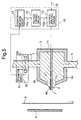
- FIG. 5 is a block diagram showing another embodiment of the present invention.
- the electrostatic ink-jet recording apparatus of this embodiment has a recording head 3 provided with an ink chamber 1 storing ink 14 containing electrified toner particles and having an ejection opening 7 at one end and ejection electrodes 4a for ejecting the toner particles from the ejection opening 7.
- a counter electrode 6 faces with the ejection opening 7 through a recording medium 8.
- a toner concentration detection device 9 for measuring the toner particle concentration in the ink 14.
- the control unit 10 is provided with a concentration decision circuit 11 for deciding a measured toner particle concentration.
- a voltage control circuit 12 for controlling a pulse voltage output to be applied to the ejection electrodes 4a in accordance with the decision by the concentration decision circuit 11.
- a voltage applying circuit 13 is provided for applying a voltage to the ejection electrodes 4a in accordance with the output of the voltage control circuit 12.
- the toner concentration detection device 9 measures an amount of toner for a certain time by a transmission-type optical sensor 91 and an integration circuit 92.
- the concentration decision section 11 decides a toner particle concentration measured by the toner concentration detection unit 9.
- the voltage control section 12 controls a pulse voltage 12a to be applied to the ejection electrodes 4a in accordance with a decision voltage 11a by the concentration decision circuit 11.
- the voltage applying circuit 13 for applying the pulse voltage 12a to the ejection electrodes 4a in accordance with the pulse voltage 12a of the voltage control circuit 12.
- the toner concentration detection device 9 time-measures an amount of toner by a transmission-type optical sensor 91 and an integration circuit 92.
- the concentration measured by the toner concentration detection device 9 is shown by one of 16 divided values by using, for example, a 4-bit A-D converter of the concentration decision circuit 11.
- the relation between the toner particle concentration in the ink 14 and the time required to eject toner particles from the ejection opening 7 is previously stored in the ROM table 20 as shown in Fig. 4 in the voltage control circuit 12. For example, by using the 4-bit A-D converter, voltage applying times of 16 levels are specified. A toner concentration is detected by the toner concentration detection device 9 before starting printing to convert the concentration into a digital value by the concentration decision circuit 11. Pulse widths are changed by the pulse width change circuit 18 correspondingly to the digital value and a voltage is applied to the ejection electrodes 4a by the voltage applying circuit 13.
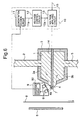
- FIG. 6 is a block diagram showing still another embodiment of the present invention.
- This embodiment is a variation of foregoing embodiment as shown in Fig. 5.
- a toner concentration detection device 9 is disposed toward an ejection opening 7 and constructed by a reflection-type optical sensor 91 and an integration circuit 92.
- This composition enables to detect toner concentration on ejection opening 7 by intensity of reflection light.
- an electrostatic ink-jet recording apparatus of the present invention makes it possible to obtain an almost constant dot diameter and a stable printing quality independently of the change of ink characteristics by measuring a toner potential of an ejection opening, determining a time until reaching a potential high enough for toner particles to be ejected in accordance with the measurement result, and applying a voltage to ejection electrodes for a proper time.
- a recording head having a plurality of ejection electrodes makes it possible to obtain an almost constant dot diameter and a stable printing quality independently of the change of ink characteristics by measuring the toner potential of an ejection opening every ejection electrode or every several groups, determining a time until reaching a potential high enough for toner particles to be ejected in accordance with the measurement result, and applying a voltage to the ejection electrodes for a proper time.
- the toner concentration in ink is measured, a time until reaching a potential high enough for toner particles to be ejected is determined in accordance with the measurement result, and a time for applying a voltage to ejection electrodes is determined.
Landscapes
- Particle Formation And Scattering Control In Inkjet Printers (AREA)
- Printers Or Recording Devices Using Electromagnetic And Radiation Means (AREA)
Claims (16)
- Dispositif d'enregistrement à jet d'encre électrostatique comprenant :(a) une chambre d'encre (1) stockant de l'encre contenant des particules de toner électrisées et comportant une ouverture d'éjection (7) à une extrémité ;(b) une électrode d'éjection (4a) pour éjecter lesdites particules de toner à partir de ladite ouverture d'éjection (7) ;(c) une contre-électrode (6) faisant face à ladite ouverture d'éjection (7) à travers un support d'enregistrement (8) ;(d) un circuit de détection de concentration de toner (9) pour mesurer ladite concentration de particules de toner dans ladite encre ; et(e) un circuit de commande (10) pour commander une impulsion de tension d'éjection à appliquer à ladite électrode d'éjection, ledit circuit de commande comprenant :(e1) un circuit de comparaison qui compare une tension correspondant à ladite concentration de particules de toner détectée par ledit circuit de détection de concentration de toner (9) avec une tension de référence ;(e2) un circuit de modification de durée d'impulsion (18) qui modifie une durée d'impulsion de ladite impulsion de tension d'éjection sur la base d'un résultat de comparaison délivré par ledit circuit de comparaison (11, 16).
- Dispositif selon la revendication 1, dans lequel ledit circuit de détection de concentration de toner (9) comporte des moyens de détection de potentiel pour détecter un potentiel électrique de ladite ouverture d'éjection.
- Dispositif selon la revendication 2, dans lequel lesdits moyens de détection de potentiel sont disposés adjacents à ladite électrode d'éjection.
- Dispositif selon la revendication 1, 2 ou 3, dans lequel ledit circuit de détection de concentration de toner (9) comporte des moyens de détection d'intensité de lumière (91) pour détecter une intensité de lumière d'une lumière qui pénètre à travers ladite encre.
- Dispositif selon la revendication 4, dans lequel lesdits moyens de détection d'intensité de lumière (91) détectent ladite intensité de lumière de ladite lumière qui pénètre à travers ladite encre dans un orifice d'entrée (2) de ladite chambre d'encre (1).
- Dispositif selon l'une quelconque des revendications 1 à 3, dans lequel ledit circuit de détection de concentration de toner (9) comporte des moyens de détection d'intensité de lumière pour détecter une intensité de lumière d'une lumière réfléchie par ladite encre.
- Dispositif selon la revendication 6, dans lequel lesdits moyens de détection d'intensité de lumière (91) sont disposés adjacents à ladite ouverture d'éjection (7).
- Dispositif selon l'une quelconque des revendications 1 à 7, dans lequel ledit circuit de commande (10) comprend :des moyens de décision de concentration (11) pour lire un potentiel électrique détecté sur une base d'une sortie provenant dudit circuit de détection de concentration de toner (9) et pour décider ensuite d'une sortie après comparaison du potentiel électrique détecté avec un potentiel de référence,des moyens de commande de tension (12) pour commander ladite tension d'éjection à appliquer à ladite électrode d'éjection (4a) conformément à une décision prise par lesdits moyens de décision de concentration (11), etdes moyens d'application de tension (13) pour appliquer ladite tension d'éjection commandée par lesdits moyens de commande de tension (12) à ladite électrode d'éjection (4a) conformément à des informations d'impression.
- Dispositif selon la revendication 8, dans lequel lesdits moyens de décision de concentration (11) délivrent deux valeurs supérieure et inférieure à un potentiel de référence en comparant une concentration détectée avec ledit potentiel de référence.
- Dispositif selon la revendication 8, dans lequel lesdits moyens de décision de concentration (11) sortent une concentration en tant que pluralité de valeurs en convertissant ledit potentiel détecté d'une valeur analogique en une valeur numérique.
- Dispositif selon la revendication 10, dans lequel
lesdits moyens de commande de tension (12) comprennent une table de mémoire morte (20) pour mémoriser au moins l'une de valeurs prédéterminées de hauteur d'impulsion, de durée d'impulsion et/ou de fréquence d'impulsion d'une tension d'impulsion à appliquer à ladite électrode d'éjection, et lisent une valeur optimale de ladite tension d'impulsion dans ladite table de mémoire morte conformément auxdites valeurs desdits moyens de décision de concentration et délivrent ladite valeur. - Dispositif selon l'une quelconque des revendications 8 à 11, dans lequel lesdits moyens de commande de tension (12) changent et délivrent des hauteurs d'impulsion, des durées d'impulsion et des fréquences d'impulsion d'une tension d'impulsion à appliquer à ladite électrode d'éjection (4a) conformément à ladite sortie desdits moyens de décision de concentration (11).
- Dispositif selon l'une quelconque des revendications 1 à 12, dans lequel ledit circuit de détection de concentration (9) délivre une valeur de concentration en tant que valeur numérique correspondant à l'une d'une pluralité de valeurs numériques, lesdits moyens de concentration délivrant ladite valeur numérique en effectuant une conversion analogique-numérique dudit potentiel détecté.
- Dispositif selon la revendication 13, dans lequel lesdits moyens de commande de tension comprennent une table de mémoire morte (20) pour mémoriser au moins l'une de valeurs prédéterminées de hauteur d'impulsion, de durée d'impulsion et/ou de fréquence d'impulsion d'une tension d'impulsion à appliquer à ladite électrode d'éjection (4a), lesdites valeurs prédéterminées de hauteur d'impulsion, de durée d'impulsion et de fréquence d'impulsion correspondant à des valeurs respectives parmi lesdites valeurs numériques, et
dans lequel lesdits moyens de commande de tension (12) lisent une valeur optimale de ladite tension d'impulsion dans ladite table de mémoire morte (20) conformément à ladite valeur numérique délivrée par ledit circuit de détection de concentration et délivrent ladite valeur. - Dispositif selon l'une quelconque des revendications 1 à 14, dans lequel ledit circuit de commande comprend :un processeur (16) qui génère une première tension d'éjection basée sur une sortie dudit circuit de comparaison, ledit processeur commandant ledit circuit de modification de durée d'impulsion pour modifier une durée d'impulsion de ladite première tension d'éjection lorsque ladite concentration de particules de toner détectée par ledit circuit de détection de concentration de toner est différente d'une valeur fixée, ledit circuit de commande appliquant ladite première tension d'éjection à ladite électrode d'éjection, etdans lequel ledit circuit de détection de concentration de toner (9) détecte une deuxième concentration de particules de toner en conséquence de l'application de ladite première tension d'éjection à ladite électrode d'éjection, ledit circuit de comparaison comparant une tension correspondant à ladite deuxième concentration de particules de toner à ladite tension de référence, et ledit processeur générant une deuxième tension d'éjection avec une durée d'impulsion modifiée davantage, ledit circuit de commande appliquant ladite deuxième tension d'éjection à ladite électrode d'éjection pour une impression réelle si ladite deuxième concentration de particules de toner est supérieure à ladite valeur fixée, ou générant des signaux d'éjection supplémentaires avec des durées d'impulsion modifiées davantage jusqu'à une correspondance avec ladite valeur de référence.
- Dispositif selon l'une quelconque des revendications 1 à 15, dans lequel ledit circuit de commande comprend :un circuit de modification de fréquence d'impulsion (19) qui modifie une fréquence à laquelle des tensions d'éjection sont appliquées à l'électrode d'éjection pour impression, ledit circuit de modification de fréquence d'impulsion modifiant ladite fréquence sur la base de la durée d'impulsion modifiée par ledit circuit de modification de durée d'impulsion (18).
Applications Claiming Priority (6)
| Application Number | Priority Date | Filing Date | Title |
|---|---|---|---|
| JP22711696A JP2885716B2 (ja) | 1996-08-28 | 1996-08-28 | 静電式インクジェット記録装置 |
| JP22711596A JP2826528B2 (ja) | 1996-08-28 | 1996-08-28 | 静電式インクジェット記録装置 |
| JP22711696 | 1996-08-28 | ||
| JP22711596 | 1996-08-28 | ||
| JP227116/96 | 1996-08-28 | ||
| JP227115/96 | 1996-08-28 |
Publications (3)
| Publication Number | Publication Date |
|---|---|
| EP0827832A2 EP0827832A2 (fr) | 1998-03-11 |
| EP0827832A3 EP0827832A3 (fr) | 1999-02-03 |
| EP0827832B1 true EP0827832B1 (fr) | 2002-12-04 |
Family
ID=26527521
Family Applications (1)
| Application Number | Title | Priority Date | Filing Date |
|---|---|---|---|
| EP97114844A Expired - Lifetime EP0827832B1 (fr) | 1996-08-28 | 1997-08-27 | Dispositif électrostatique d'enregistrement à jet d'encre |
Country Status (3)
| Country | Link |
|---|---|
| US (1) | US6113219A (fr) |
| EP (1) | EP0827832B1 (fr) |
| DE (1) | DE69717566T2 (fr) |
Families Citing this family (1)
| Publication number | Priority date | Publication date | Assignee | Title |
|---|---|---|---|---|
| EP1552922A1 (fr) * | 2004-01-09 | 2005-07-13 | Kodak Polychrome Graphics, LLC | Fabrication de plaques flexographiques par impression par jet d'encre |
Family Cites Families (4)
| Publication number | Priority date | Publication date | Assignee | Title |
|---|---|---|---|---|
| JPS56127461A (en) * | 1980-03-12 | 1981-10-06 | Matsushita Electric Ind Co Ltd | Direct recording device |
| JPS62124567A (ja) * | 1985-11-26 | 1987-06-05 | Matsushita Graphic Commun Syst Inc | 液体現像静電記録装置 |
| DE69230111T2 (de) * | 1991-12-18 | 2000-01-20 | Tonejet Corp. Pty. Ltd., Eastwood | Methode und vorrichtung zur herstellung von diskreten agglomeraten von einem teilchenförmigen material |
| JP3315268B2 (ja) * | 1994-09-22 | 2002-08-19 | 株式会社東芝 | 画像形成装置 |
-
1997
- 1997-08-27 US US08/917,769 patent/US6113219A/en not_active Expired - Fee Related
- 1997-08-27 DE DE69717566T patent/DE69717566T2/de not_active Expired - Fee Related
- 1997-08-27 EP EP97114844A patent/EP0827832B1/fr not_active Expired - Lifetime
Also Published As
| Publication number | Publication date |
|---|---|
| DE69717566D1 (de) | 2003-01-16 |
| EP0827832A3 (fr) | 1999-02-03 |
| US6113219A (en) | 2000-09-05 |
| EP0827832A2 (fr) | 1998-03-11 |
| DE69717566T2 (de) | 2003-04-10 |
Similar Documents
| Publication | Publication Date | Title |
|---|---|---|
| KR100249877B1 (ko) | 각각의 잉크 방출 개구에 대응하여 복수개의 잉크 방출 히터를 갖는 잉크젯 헤드를 이용하는 잉크젯 장치 | |
| US6357846B1 (en) | Ink jet recording apparatus and recording method using the same | |
| US5880751A (en) | Ink jet recording apparatus and ink droplet amount ejection control method therefor | |
| KR0137615B1 (ko) | 잉크 제트 기록 방법 및 장치(Ink Jet Recording Method and Apparatus) | |
| JP3639330B2 (ja) | インク・ジェット・プリンタ | |
| EP0461936B1 (fr) | Méthode de commande pour tête à jet d'encre | |
| JP3152243B2 (ja) | 高周波数ドロップオンデマンド型インクジェットシステム | |
| JP2003311971A (ja) | 連続流インクジェット印刷機において一定の液滴体積を維持するための装置と方法 | |
| EP0864424B1 (fr) | Dispositif d'enregistrement à jet d'encre et méthode de commande d'une quantité d'encre déchargée après une interruption dans l'enregistrement | |
| US5300969A (en) | Ink jet recording method and apparatus for maintaining efficient ink viscosity | |
| JP2947237B2 (ja) | 画像記録装置 | |
| US20100149235A1 (en) | Liquid-ejection testing method, liquid-ejection testing device and computer readable medium | |
| US20060125868A1 (en) | Liquid-ejection testing method, liquid-ejection testing device, and computer-readable medium | |
| US6113219A (en) | Electrostatic ink jet recording apparatus capable of realizing stable ejection of ink | |
| EP0688130B1 (fr) | Procédé et tête d'impression pour la reproduction de représentations à tonalités et à gradients | |
| EP0315206B1 (fr) | Imprimante par points | |
| EP1138490B1 (fr) | Tête d'impression à jet d'encre et dispositif d'impression à jet d'encre | |
| EP0838335A2 (fr) | Appareil d'enregistrement à jet d'encre | |
| US6331041B1 (en) | Inkjet printing apparatus | |
| EP0758584B1 (fr) | Imprimante par jet d'encre utilisant une encre contenant des particules de pigment | |
| US6198493B1 (en) | Recording apparatus | |
| US7134328B2 (en) | Liquid-ejection testing method, liquid-ejection testing device, and computer-readable medium | |
| JP2885716B2 (ja) | 静電式インクジェット記録装置 | |
| US5808632A (en) | Recording apparatus and method using ink jet recording head | |
| JP2826528B2 (ja) | 静電式インクジェット記録装置 |
Legal Events
| Date | Code | Title | Description |
|---|---|---|---|
| PUAI | Public reference made under article 153(3) epc to a published international application that has entered the european phase |
Free format text: ORIGINAL CODE: 0009012 |
|
| AK | Designated contracting states |
Kind code of ref document: A2 Designated state(s): DE FR GB |
|
| PUAL | Search report despatched |
Free format text: ORIGINAL CODE: 0009013 |
|
| AK | Designated contracting states |
Kind code of ref document: A3 Designated state(s): AT BE CH DE DK ES FI FR GB GR IE IT LI LU MC NL PT SE |
|
| 17P | Request for examination filed |
Effective date: 19990707 |
|
| AKX | Designation fees paid |
Free format text: DE FR GB |
|
| 17Q | First examination report despatched |
Effective date: 20000203 |
|
| GRAG | Despatch of communication of intention to grant |
Free format text: ORIGINAL CODE: EPIDOS AGRA |
|
| GRAG | Despatch of communication of intention to grant |
Free format text: ORIGINAL CODE: EPIDOS AGRA |
|
| GRAG | Despatch of communication of intention to grant |
Free format text: ORIGINAL CODE: EPIDOS AGRA |
|
| GRAH | Despatch of communication of intention to grant a patent |
Free format text: ORIGINAL CODE: EPIDOS IGRA |
|
| GRAH | Despatch of communication of intention to grant a patent |
Free format text: ORIGINAL CODE: EPIDOS IGRA |
|
| GRAA | (expected) grant |
Free format text: ORIGINAL CODE: 0009210 |
|
| AK | Designated contracting states |
Kind code of ref document: B1 Designated state(s): DE FR GB |
|
| REG | Reference to a national code |
Ref country code: GB Ref legal event code: FG4D |
|
| REF | Corresponds to: |
Ref document number: 69717566 Country of ref document: DE Date of ref document: 20030116 |
|
| ET | Fr: translation filed | ||
| PLBE | No opposition filed within time limit |
Free format text: ORIGINAL CODE: 0009261 |
|
| STAA | Information on the status of an ep patent application or granted ep patent |
Free format text: STATUS: NO OPPOSITION FILED WITHIN TIME LIMIT |
|
| 26N | No opposition filed |
Effective date: 20030905 |
|
| PGFP | Annual fee paid to national office [announced via postgrant information from national office to epo] |
Ref country code: FR Payment date: 20060808 Year of fee payment: 10 |
|
| PGFP | Annual fee paid to national office [announced via postgrant information from national office to epo] |
Ref country code: GB Payment date: 20060823 Year of fee payment: 10 |
|
| PGFP | Annual fee paid to national office [announced via postgrant information from national office to epo] |
Ref country code: DE Payment date: 20060824 Year of fee payment: 10 |
|
| GBPC | Gb: european patent ceased through non-payment of renewal fee |
Effective date: 20070827 |
|
| REG | Reference to a national code |
Ref country code: FR Ref legal event code: ST Effective date: 20080430 |
|
| PG25 | Lapsed in a contracting state [announced via postgrant information from national office to epo] |
Ref country code: DE Free format text: LAPSE BECAUSE OF NON-PAYMENT OF DUE FEES Effective date: 20080301 |
|
| PG25 | Lapsed in a contracting state [announced via postgrant information from national office to epo] |
Ref country code: FR Free format text: LAPSE BECAUSE OF NON-PAYMENT OF DUE FEES Effective date: 20070831 |
|
| PG25 | Lapsed in a contracting state [announced via postgrant information from national office to epo] |
Ref country code: GB Free format text: LAPSE BECAUSE OF NON-PAYMENT OF DUE FEES Effective date: 20070827 |