EP0828036A2 - Dach und Montagesystem dafür - Google Patents
Dach und Montagesystem dafür Download PDFInfo
- Publication number
- EP0828036A2 EP0828036A2 EP97114923A EP97114923A EP0828036A2 EP 0828036 A2 EP0828036 A2 EP 0828036A2 EP 97114923 A EP97114923 A EP 97114923A EP 97114923 A EP97114923 A EP 97114923A EP 0828036 A2 EP0828036 A2 EP 0828036A2
- Authority
- EP
- European Patent Office
- Prior art keywords
- roof
- roof panel
- solar battery
- end engaging
- engaging portion
- Prior art date
- Legal status (The legal status is an assumption and is not a legal conclusion. Google has not performed a legal analysis and makes no representation as to the accuracy of the status listed.)
- Granted
Links
Images


Classifications
-
- E—FIXED CONSTRUCTIONS
- E04—BUILDING
- E04D—ROOF COVERINGS; SKY-LIGHTS; GUTTERS; ROOF-WORKING TOOLS
- E04D13/00—Special arrangements or devices in connection with roof coverings; Protection against birds; Roof drainage ; Sky-lights
-
- H—ELECTRICITY
- H10—SEMICONDUCTOR DEVICES; ELECTRIC SOLID-STATE DEVICES NOT OTHERWISE PROVIDED FOR
- H10F—INORGANIC SEMICONDUCTOR DEVICES SENSITIVE TO INFRARED RADIATION, LIGHT, ELECTROMAGNETIC RADIATION OF SHORTER WAVELENGTH OR CORPUSCULAR RADIATION
- H10F19/00—Integrated devices, or assemblies of multiple devices, comprising at least one photovoltaic cell covered by group H10F10/00, e.g. photovoltaic modules
- H10F19/80—Encapsulations or containers for integrated devices, or assemblies of multiple devices, having photovoltaic cells
-
- E—FIXED CONSTRUCTIONS
- E04—BUILDING
- E04D—ROOF COVERINGS; SKY-LIGHTS; GUTTERS; ROOF-WORKING TOOLS
- E04D1/00—Roof covering by making use of tiles, slates, shingles, or other small roofing elements
- E04D1/36—Devices for sealing the spaces or joints between roof-covering elements
- E04D1/365—Sealing strips between lateral sides of roof-covering elements
-
- E—FIXED CONSTRUCTIONS
- E04—BUILDING
- E04D—ROOF COVERINGS; SKY-LIGHTS; GUTTERS; ROOF-WORKING TOOLS
- E04D3/00—Roof covering by making use of flat or curved slabs or stiff sheets
- E04D3/36—Connecting; Fastening
- E04D3/361—Connecting; Fastening by specially-profiled marginal portions of the slabs or sheets
-
- E—FIXED CONSTRUCTIONS
- E04—BUILDING
- E04D—ROOF COVERINGS; SKY-LIGHTS; GUTTERS; ROOF-WORKING TOOLS
- E04D3/00—Roof covering by making use of flat or curved slabs or stiff sheets
- E04D3/36—Connecting; Fastening
- E04D3/366—Connecting; Fastening by closing the space between the slabs or sheets by gutters, bulges, or bridging elements, e.g. strips
-
- H—ELECTRICITY
- H02—GENERATION; CONVERSION OR DISTRIBUTION OF ELECTRIC POWER
- H02S—GENERATION OF ELECTRIC POWER BY CONVERSION OF INFRARED RADIATION, VISIBLE LIGHT OR ULTRAVIOLET LIGHT, e.g. USING PHOTOVOLTAIC [PV] MODULES
- H02S20/00—Supporting structures for PV modules
- H02S20/20—Supporting structures directly fixed to an immovable object
- H02S20/22—Supporting structures directly fixed to an immovable object specially adapted for buildings
- H02S20/23—Supporting structures directly fixed to an immovable object specially adapted for buildings specially adapted for roof structures
-
- H—ELECTRICITY
- H02—GENERATION; CONVERSION OR DISTRIBUTION OF ELECTRIC POWER
- H02S—GENERATION OF ELECTRIC POWER BY CONVERSION OF INFRARED RADIATION, VISIBLE LIGHT OR ULTRAVIOLET LIGHT, e.g. USING PHOTOVOLTAIC [PV] MODULES
- H02S40/00—Components or accessories in combination with PV modules, not provided for in groups H02S10/00 - H02S30/00
- H02S40/30—Electrical components
- H02S40/36—Electrical components characterised by special electrical interconnection means between two or more PV modules, e.g. electrical module-to-module connection
-
- E—FIXED CONSTRUCTIONS
- E04—BUILDING
- E04D—ROOF COVERINGS; SKY-LIGHTS; GUTTERS; ROOF-WORKING TOOLS
- E04D1/00—Roof covering by making use of tiles, slates, shingles, or other small roofing elements
- E04D1/34—Fastenings for attaching roof-covering elements to the supporting elements
- E04D2001/3452—Fastenings for attaching roof-covering elements to the supporting elements characterised by the location of the fastening means
- E04D2001/3458—Fastenings for attaching roof-covering elements to the supporting elements characterised by the location of the fastening means on the upper or lower transverse edges of the roof covering elements
-
- F—MECHANICAL ENGINEERING; LIGHTING; HEATING; WEAPONS; BLASTING
- F24—HEATING; RANGES; VENTILATING
- F24S—SOLAR HEAT COLLECTORS; SOLAR HEAT SYSTEMS
- F24S25/00—Arrangement of stationary mountings or supports for solar heat collector modules
-
- Y—GENERAL TAGGING OF NEW TECHNOLOGICAL DEVELOPMENTS; GENERAL TAGGING OF CROSS-SECTIONAL TECHNOLOGIES SPANNING OVER SEVERAL SECTIONS OF THE IPC; TECHNICAL SUBJECTS COVERED BY FORMER USPC CROSS-REFERENCE ART COLLECTIONS [XRACs] AND DIGESTS
- Y02—TECHNOLOGIES OR APPLICATIONS FOR MITIGATION OR ADAPTATION AGAINST CLIMATE CHANGE
- Y02B—CLIMATE CHANGE MITIGATION TECHNOLOGIES RELATED TO BUILDINGS, e.g. HOUSING, HOUSE APPLIANCES OR RELATED END-USER APPLICATIONS
- Y02B10/00—Integration of renewable energy sources in buildings
- Y02B10/10—Photovoltaic [PV]
-
- Y—GENERAL TAGGING OF NEW TECHNOLOGICAL DEVELOPMENTS; GENERAL TAGGING OF CROSS-SECTIONAL TECHNOLOGIES SPANNING OVER SEVERAL SECTIONS OF THE IPC; TECHNICAL SUBJECTS COVERED BY FORMER USPC CROSS-REFERENCE ART COLLECTIONS [XRACs] AND DIGESTS
- Y02—TECHNOLOGIES OR APPLICATIONS FOR MITIGATION OR ADAPTATION AGAINST CLIMATE CHANGE
- Y02E—REDUCTION OF GREENHOUSE GAS [GHG] EMISSIONS, RELATED TO ENERGY GENERATION, TRANSMISSION OR DISTRIBUTION
- Y02E10/00—Energy generation through renewable energy sources
- Y02E10/50—Photovoltaic [PV] energy
-
- Y—GENERAL TAGGING OF NEW TECHNOLOGICAL DEVELOPMENTS; GENERAL TAGGING OF CROSS-SECTIONAL TECHNOLOGIES SPANNING OVER SEVERAL SECTIONS OF THE IPC; TECHNICAL SUBJECTS COVERED BY FORMER USPC CROSS-REFERENCE ART COLLECTIONS [XRACs] AND DIGESTS
- Y10—TECHNICAL SUBJECTS COVERED BY FORMER USPC
- Y10S—TECHNICAL SUBJECTS COVERED BY FORMER USPC CROSS-REFERENCE ART COLLECTIONS [XRACs] AND DIGESTS
- Y10S136/00—Batteries: thermoelectric and photoelectric
- Y10S136/291—Applications
Definitions
- the present invention relates to a horizontal-roofing roof, a joint for horizontal-roofing roof, and a mounting method of horizontal-roofing roof and, more particularly, to a roof integrated with solar battery and a mounting method thereof.
- the solar battery is installed by use of some frame on the existing roof, and conventional solar battery modules can thus be used as they are.
- the installation cost is high and the appearance is poor. Therefore, the latter method is drawing attention recently.
- Japanese Laid-open Patent Application No. 59-152670 discloses electrical connection of horizontal roofing, but it has a problem that once solar battery modules have been laid, it becomes impossible to measure an output of solar battery of each module and that checking works thereof require work amounts substantially equal to total replacement.
- the present invention solved the above problems and provides a horizontal-roofing roof panel, a combination roofing panel and solar battery, a joint for horizontal-roofing roof, and a mounting method of horizontal-roofing roof, for realizing partial replacement of roof panel in the event of occurrence of a failure in the roof panel, especially, in the combination solar battery and roof panel.
- the present invention provides means capable of specifying a faulty combination solar battery and roof panel in the event of occurrence of a failure.
- the present invention provides means that can prevent occurrence of troubles such as wiring errors due to complexity of wiring works upon mounting of combination solar battery and roof panels and that allows a worker to easily deal with a wiring error in the event of occurrence thereof.
- the present invention solved the problems discussed above by use of the following means.
- the roof panel according to the present invention With the horizontal-roofing roof panel according to the present invention after mounted, when the lower-end engaging portion is removed and when the keep members of joint on the both sides are removed, the roof panel becomes fixed only on the upper side, so that the flexible roof panel can be turned up after mounted. As a result, only some retaining clips can be removed even after mounting of roof. Therefore, the invention realizes such special action that the roof panels horizontally roofed become partly replaceable even after mounted.
- the joint according to the present invention has the opening portion at least in the bottom member, the output of each solar battery can be checked readily through the opening portion by removing the cover member of joint even after mounting of roof, whereby a faulty combination solar battery and roof panel can be specified readily.
- the engaging portions of the roof panel are formed in double wall structure against the sheathing roof board, whereby water going through gaps of screw can be returned to the lower roof panel, thus maintaining the flashing equivalent to that heretofore.
- the fastener according to the present invention further has a merit of preventing rain or the like from directly hitting the fastener, because the roof panels are fastened at an opening portion deep inside of the interconnecting portion of roof. Therefore, the invention has the function to overcome a problem that screws are drawn out by snow in the areas of high snowfall, for example.
- the horizontal-roofing roof panel according to the present invention it becomes possible to turn up an intermediate portion of the horizontal-roofing roof and thus to perform the electric wiring work easily for the solar battery of each section with access to the terminal portion on the back side of roof panel. Therefore, even if there is a connection error upon mounting of roof, the wiring can be rearranged thereafter.
- the horizontal-roofing roof panel according to the present invention permits the intermediate portion of roof panel to be turned up, the terminal portion on the back side of roof panel or the like can be checked readily even after mounting of roof, and it is also possible to repair the terminal portion or the like as well as the wiring at the working site.
- Fig. 1 shows a typical example of the horizontal-roofing roof panel in the present invention, which is composed mainly of backing 101, solar battery element 102, sealing material 103, junction box 104, and wire member 105.
- Numeral 106 designates a lower-end engaging portion of a roof panel located upstream and 107 an upper-end engaging portion of a roof panel located downstream.
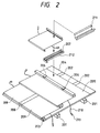
- Fig. 2 shows a mounting example of the combination solar battery and roof in the present embodiment, wherein reference numeral 201 designates structural members of purlins, 202 rafters, 203 an eave arabesque, 204 sheathing roof boards which are a roof bed material, 205 an asphalt roofing, 206 retaining clips, 207 a drip plate which is a joint bottom member, 208 a joint cover which is a joint cover member, 209 roof panels, 210 a wiring member, 211 a keep plate which is a joint keep member, and 212 an opening portion.
- reference numeral 201 designates structural members of purlins, 202 rafters, 203 an eave arabesque, 204 sheathing roof boards which are a roof bed material, 205 an asphalt roofing, 206 retaining clips, 207 a drip plate which is a joint bottom member, 208 a joint cover which is a joint cover member, 209 roof panels, 210 a wiring member, 211 a keep plate which is a joint keep
- roof the roof panels of the present invention directly on the rafters or on beams corresponding to the rafters without provision of sheathing roof boards.
- the engaging portion of the roof panel according to the present invention are shown in Fig. 3.
- the upper-end engaging portion of the lower roof panel is fixed to the sheathing roof board 204 through the retaining clip 206 by a nail or a drill screw or the like.
- the retaining clip is shaped as shown in Fig. 3, wherein an inside claw thereof is firmly engaged with a part of the upper-end engaging portion 107 of the lower roof panel. Then the lower-end engaging portion 106 of the upper roof panel is coupled with the upper-end engaging portion 107 of the lower roof panel and an outside claw of the retaining clip 206 is inserted into a recess of the lower-end engaging portion 106 of the upper roof panel.
- the upper-end engaging portion of the upper roof panel is also fixed by the retaining clip 206 in the same manner. Then the engaging portions are bored and fastened by a fastener 214. These procedures are repeated.
- the engaging portions may be preliminarily bored at production facilities.
- a specific example of the fastener 214 is a blind rivet, which is used suitably.
- the blind rivet has sufficient mechanical strength, while it can be broken readily by drill to be removed; and a new rivet can be remounted easily by a dedicated device.
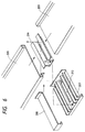
- Fig. 6 Details of the connecting part in the horizontal direction of the roof panel according to the present invention are shown in Fig. 6.
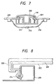
- Fig. 7 is a cross-sectional view showing the assembled relation of the roof panel, the joint drip plate, the keep plate and the joint cover after the members of Fig. 6 are assembled.
- Fig. 8 is a cross-sectional view showing the assembled relation of the roof panel, the joint drip plate and the joint cover after the members of Fig. 6 are assembled.
- a joint drip plate 207 is placed below an adjacent area between two adjacent roof panels 209 and functions to guide rainwater flowing into the adjacent area onto the roof panel located downstream.
- the joint drip plate 207 has a plurality of flange portions of a fin shape for more certain flashing.
- a keep plate 211 is placed on the joint drip plate 207 and a joint cover 208 is placed so as to cover the keep plate 211.
- the keep plate 211 and joint drip plate 207 each are provided with an opening portion 212 through which the wire members 210 can be drawn out.
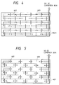
- Fig. 4 is a drawing to show connection of back wire 402 between the roof panels in the roof according to the present embodiment, wherein the roof panels constitute solar battery strings in each of which adjacent combination solar battery and roof panels are connected in series in order from the positive electrode to the negative electrode or from the negative electrode to the positive electrode.
- a plurality of solar battery strings are provided, generation voltages thereof are equal, and each voltage is set so as to be an input voltage (for example, 200 V) of inverter.
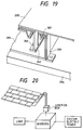
- Outputs of the plural solar battery strings are collected independently of each other into a DC combiner box and are connected in parallel therein (Fig. 20).
- a breaker is provided at a preliminary section before the contact point of the parallel connection of each solar battery string.
- the solar battery string can be electrically disconnected to be subjected to maintenance.
- Hatched members of 401 etc. are roof panels, so called as dummy plates, having no solar battery element. These members are used to supplement incomplete portions produced because of dimensional differences between the dimensions of roof panel and the length of the roof occurring in roofing of roof, and they are also used for works such as gable finish or ridge finish at the edge portions and used as a collecting place of wires from the plural roof panels.
- two horizontal strings form a basic unit as to the output of each solar battery, and the output is guided below the dummy plates formed near the edge of roof and then through the ridge or through the eaves to be connected to the DC combiner box inside of the house.
- a power inverter device is connected to the DC combiner box and the power is then supplied to a load inside of the house or to the system electric power.
- Fig. 5 shows another installation mode using two types of combination solar battery and horizontal-roofing roof panels the positive electrodes and the negative electrodes of which are arranged symmetric with each other.
- wires can be laid in a simple arrangement and the total length of the wires from the solar battery elements can be decreased, thus achieving effects of reduction in cost of wiring material and reduction in power loss.
- Fig. 9 shows a fixing state by use of a bolt in the present invention, in which reference numeral 900 designates a retaining clip and 901 a screw receiving member.
- Described below are the members constituting the roof panel and the members associated with the mounting of roof panel.
- the backing 101 needs to have such flexural rigidity as to permit the portion forming the lower-end engaging portion 106 to be turned up and then to be brought back into the original state.
- This flexural rigidity is determined preferably so that human power can turn up the base.
- the displacement amount x for disengaging the seam joint needs to be at least 1 cm. Therefore, the flexural rigidity E of the backing is preferably smaller than 1.6 ⁇ 10 4 kgcm 2 . However, this value varies up and down slightly depending upon the shape of the lower-end engaging portion.
- the material for the backing can be selected from steel sheets, sheets of nonferrous metals, or plastics.
- steel sheets include surface-treated steel sheets, coated steel sheets, alloys or special steels containing another element, and composite steel sheets laminated with a heat-insulating material or the like.
- the material is selected from hot-dip galvanized steel sheets, galphan, galvalium steel sheets, hot-dip aluminized steel sheets, copper-plated steel sheets, polyvinyl chloride precoated steel plates, fluorocarbon resin steel sheets, stainless steel sheets, high damping steel sheets, heat-insulating galvanized sheet iron, atmosphere corrosion resisting steel, and the aforementioned coated steel sheets; or from the nonferrous metals, such as copper sheets, aluminum alloy sheets, zinc alloy sheets, lead sheets, titanium sheets, and the aforementioned coated color sheets.
- the type of the solar battery element 102 used in the present invention may be of any form, either single crystal, polycrystal, fine crystal, or amorphous.
- the solar battery element may be either of an Si based material or of a compound based material.
- the amorphous solar battery element is preferable because of possession of flexibility. Since the amorphous solar battery element recovers its degradation by heat, it is suitable for use on the roof.
- Fig. 10 shows a cross-sectional view of a non-monocrystal silicon solar battery as an example of the flexible solar battery element.
- Substrate 300 is a member for mechanically supporting semiconductor layer 302 in the case of the thin-film solar battery like amorphous silicon and it is also used as an electrode in some cases.
- the substrate needs to have such heat resistance as to resist heating temperatures upon film formation of the semiconductor layer 302, but may be electrically conductive or insulative.
- conductive materials include thin plates of metals such as Fe, Ni, Cr, Al, Mo, Au, Nb, Ta, V, Ti, Pt, and Pb; thin plates alloys thereof, for example, thin plates of brass, stainless steel, or the like; composites thereof; carbon sheets, galvanized steel sheets, and so on.
- metals such as Fe, Ni, Cr, Al, Mo, Au, Nb, Ta, V, Ti, Pt, and Pb
- thin plates alloys thereof for example, thin plates of brass, stainless steel, or the like
- composites thereof carbon sheets, galvanized steel sheets, and so on.
- the electrically insulating materials include films or sheets of heat-resisting synthetic resins such as polyester, polyethylene, polycarbonate, cellulose acetate, polypropylene, polyvinyl chloride, polyvinylidene chloride, polystyrene, polyamide, polyimide, and epoxy; thin plates of composites thereof with glass fiber, carbon fiber, boron fiber, metal fiber, or the like; materials obtained by depositing a metal thin film of different material and/or an insulating thin film of SiO 2 , Si 3 N 4 , Al 2 O 3 , AlN, or the like on a surface of a thin plate of these metals, a resin sheet, or the like by a surface coating treatment such as a sputtering process, a vapor deposition process, a plating process, or the like; glasses, ceramics, and so on.
- synthetic resins such as polyester, polyethylene, polycarbonate, cellulose acetate, polypropylene, polyvinyl chloride, polyvinylidene chlor
- Lower electrode (back reflecting layer) 301 is one electrode for extracting power generated in the semiconductor layer 302, which is required to have such a work function as to be an ohmic contact to the semiconductor layer 302.
- the material for the lower electrode may be selected from the so-called single metals or alloys such as Al, Ag, Pt, Au, Ni, Ti, Mo, W, Fe, V, Cr, Cu, stainless steel, brass, nichrome, SnO 2 , In 2 O 3 , ZnO, and ITO; transparent conductive oxides (TCO), and so on.
- the surface of the lower electrode 301 is preferably smooth, but it may be texturized where irregular reflection of light is expected. It is also called as a back reflecting layer.
- the lower electrode 301 does not have to be provided in particular.
- a fabrication process of the lower electrode 301 may employ such a method as plating, vapor deposition, or sputtering, which is selected properly as occasion demands.
- the semiconductor layer 302 of the solar battery element is of the semiconductor pin junction.
- a semiconductor material for making the i-layer may be selected from the so-called IV-based and IV-alloy-based amorphous semiconductors such as a-Si:H, a-Si:F, a-Si:H:F, a-SiGe:H, a-SiGe:F, a-SiGe:H:F, a-SiC:H, a-SiC:F, and a-SiC:H:F.
- a semiconductor material for making the p-layer or the n-layer can be obtained by doping the semiconductor material for making the i-layer described above with a valence electron controller.
- the raw material of the valence electron controller for obtaining the p-type semiconductor is selected from compounds containing the III element in the periodic table. Examples of the III element include Al, Ga, In, and so on.
- the valence electron controller for obtaining the n-type semiconductor may be selected from compounds containing the V-element in the periodic table. Examples of the V-element include P, N, As, and S.
- a film-forming process of the amorphous silicon semiconductor layer is selected from the well-known methods such as the vapor deposition process, the sputtering process, the RF plasma enhanced CVD process, the microwave plasma enhanced CVD process, the ECR process, the thermal CVD process, and the LPCVD process as occasion demands.
- the RF plasma enhanced CVD process for decomposing the stock gas by RF plasma and depositing silicon on the substrate is preferably used as an industrially employed process.
- the RF plasma enhanced CVD has a problem that the decomposition efficiency of stock gas is low, approximately 10 %, and a problem that the deposition rate is slow, approximately from 1 ⁇ /sec to 10 ⁇ /sec, and the microwave plasma enhanced CVD process is drawing attention as a film-forming method that can solve such problems.
- a reactor for carrying out the above film formation can be selected from well-known devices such as batch type devices or continuous film-forming devices as occasion demands.
- the so-called tandem cell or triple cell including a laminate of two or more semiconductor junctions can be applied to the solar battery of the present invention in order to increase the spectral sensitivity and the voltage.
- Upper electrode (transparent conductive film) 303 is an electrode for extracting electromotive force generated in the semiconductor layer 302, which is paired with the aforementioned lower electrode.
- the upper electrode needs to be transparent, because it is located on the light incidence side, and it is also called as a transparent conductive film.
- the upper electrode 303 desirably has the transmittance of light not less than 85 % for efficient absorption of light from the sun, a fluorescent lamp, or the like in the semiconductor layer 302, and further, electrically, it desirably has a sheet resistance value not more than 100 ⁇ / ⁇ for making electric current generated by light flow horizontally relative to the semiconductor layer 302.
- materials having such characteristics include metal oxides such as SnO 2 , In 2 O 3 , ZnO, CdO, CdSnO 4 , and ITO (In 2 O 3 + SnO 2 ).
- a fabrication process of the upper electrode 303 is properly selected from the resistance heating vapor deposition process, the electron beam heating vapor deposition process, the sputtering process, the spray process, and so on as occasion demands.
- an etching line of 304 can be formed by removing a part of the above transparent conductive film 303 by a desired method selected from the conventionally known etching techniques, for example, such as chemical etching, printing etching, and electrochemical etching.
- collector electrode 305 is formed by patterning a metal or a conductive paste by a method of sputtering, vapor deposition, printing, or bonding, or by fixing a metal line onto the transparent conductive film with a conductive paste.
- the amorphous solar battery itself, fabricated in this way, has high flexibility and it is a flexible solar battery having the characteristics suitable for the present invention.
- the location of the solar battery on the roof panel is preferably defined only within the working width in respect of simultaneous processing with the roof panel.
- the longitudinal direction of the collector electrode 305 is desirably determined to be a direction coincident with the longitudinal direction of the horizontal-roofing roof. This can prevent separation of the collector electrode.
- sealing material 103 are EVA (ethylene-vinyl acetate), EEA (ethylene-ethylacrylate), PVB (polyvinyl butyral), and so on in terms of the adhesive property with the solar battery element, weatherability, and buffer effect. For enhancing mechanical characteristics, it is used in some cases together with a filler such as nonwoven glass fabric or silica.
- EVA ethylene-vinyl acetate
- EEA ethylene-ethylacrylate
- PVB polyvinyl butyral
- a filler such as nonwoven glass fabric or silica.
- fluorine based resins are preferably applied for the surface film 110 in respect of weatherability.
- fluorine based resins include polymers of tetrafluoroethylene, TFE (TEFLON or the like available from duPont), copolymers of tetrafluoroethylene with ethylene, ETFE (TEFZEL or the like available from duPont), polyfluorovinyl (TEDLAR or the like available from duPont), polychlorofluoroethylene, CTFE (Neoflon available from Daikin Kogyo), and so on.
- An ultraviolet absorber well known may be added to these resins so as to improve the weatherability.
- a more preferred film is a film the surface of which is roughened by a method of corona discharge treatment or the like, in order to improve the adhesive property with the bonding layer. Further, a non-oriented film is more preferable so as to be ready for various types of bending.
- the sealing method includes stacking the backing, the filler, the solar battery element, the filler, and the surface film and then pressing the stack in a vacuum under heat and pressure by a vacuum laminator. After sealing, edges of the backing are bent into the shape of the roof panel.
- the junction box 104 is a box for housing the terminal for drawing the power out.
- the material for the junction box 104 needs to be excellent in the heat resistance, water resistance, electric insulation, and aging property.
- preferred materials for the junction box are plastics and, in consideration of flame retardancy, materials such as flame-retardant plastics and ceramics are preferable.
- plastics examples include engineering plastics excellent in the strength, impact resistance, heat resistance, hardness, and aging property such as Noryl, polycarbonate, polyamide, polyacetal, modified PPO, polyester, polyarylate, unsaturated polyester, phenolic resin, and epoxy resin.
- thermoplastic resins such as ABS resin, PP, and PVC can also be applied.
- the junction box is preferably located as being kept away from water-related portions in terms of the water resistance, electric insulation, and aging property, which does not limit the location thereof at all, and it is preferably located at a position to facilitate finding of wire. Therefore, in the present embodiment the junction box is disposed on the back surface of roof panel and in the central portion, thereby giving special consideration to avoiding entanglement of wire even in the case wherein the terminals of the positive and negative electrodes are wired in the opposite directions.
- the inside of the junction box is filled with a filler in the present invention.
- a filler in the present invention.
- materials for the filler include epoxy resin based adhesives, silicone based potting agents, and silicone based adhesive sealing agents with good electric insulation.
- the silicone based resins are more preferable in consideration of flexibility or the like.
- preferred materials are those of one-part type with short curing time and those with low viscosity easy to fill even fine parts.
- the curing method is preferably of the deacetonization type or of the dealcoholization type in order to avoid erosion of electrode.
- Examples of the epoxy resin based adhesives available from Three Bond Co. Ltd. are trade names "2001,” “2002H,” “2003,” “2016,” and “2022,” and the above epoxy resins can be used as mixed at a desired ratio with a curing agent selected from trade names "2102,” “2103,” “2104,” “2105F,” “2105C,” “2106,” “2131,” “2131D,” “2131F,” and “2163.”
- the present invention imparts no specific limitations on the wiring method and a variety of wiring materials and wiring means known conventionally can be applied. Especially, when the wiring structure is given on the back surface of roof panel, the conditions for the water resistance and weatherability can be relaxed, and such structure thus has an advantage of availability of interior wiring materials made of cheap materials. When connectors are used for all connections between the wire materials as in the present embodiment, the wires can be disconnected readily in the event of check, which preferably facilitates checking.
- a side edge of one roof panel is jointed with a side edge of another roof panel adjacent thereto in the direction perpendicular to the flow of roof by the flashing structure as shown in Fig. 6, which is composed of the joint drip plate 207, the joint cover plate 208, and the keep plate 211.
- the joint drip plate 207 is a plate for letting water from the side panels flow onto the lower roof panels, which may be selected from a variety of conventionally known drip plates.
- the keep plate 211 is a pedestal for fixing the side panels and for mechanically securing the joint cover 208.
- the joint cover 208 is a member for preventing the rainwater from intruding into the fastener of keep plate and for maintaining the appearance of the connecting part.
- the combination solar battery and roof panel according to the present invention is constructed so that the roof panel and the solar battery are electrically insulated from each other by the polymer filler, it does not have to have a special insulating mechanism for insulating the solar batteries adjacent to the joint drip plate and the joint cover plate from each other, the special insulating mechanism being described in Japanese Laid-open Patent Application No. 59-152670, and materials similar to those of the normal joints can be used.
- the retaining clip 206 is a metal fitting for fixing the roof panel to the base of roof, and a variety of shapes are known conventionally according to the shapes of roof panel. Since the retaining clip is a member for substantially supporting the wind endurance, the thickness thereof is thicker than that of the roof panel and a steel member having sufficient mechanical strength is used in general.
- the present embodiment employs the retaining clip having the two claws as shown in Fig. 3, wherein the first claw secures the lower panel while the second claw secures the upper panel.
- the fastener 214 is a member for mechanically coupling two seam-jointed roof panels with each other, which may be selected from a blind rivet, a screw, a drill screw, and so on. In either case the fastener is easily removable so as to enable to dismount the roof panel after mounted. Since the roof panel of the present invention is the member having such flexural rigidity as to permit the roof panel to be turned up after disconnection of seam joint, the backing used herein is relatively thin. It is, therefore, desirable to increase the strength by coupling the roof panels by the fastener 213 at the seam joint.
- the roof bed material 204 may be any material that can present the base for fixing the roofing material, and particularly preferable materials are plates having a heat insulating property; specifically, sheathing roof board of flat wood plate, mortar, cemented excelsior board, plywood, cemented chip, and insulation board.
- the roof bed material may have a backing of a heat insulating material of polystyrene foam, polyurethane foam, polyethylene foam, glass wool, rock wool, or the like.
- the air is heated between the roof panel 209 and the roof bed material 204; and as a result, in the case of use of the amorphous silicon solar batteries as solar batteries, degradation of performance of the amorphous silicon solar batteries is recovered by the heat. This can improve the performance of the amorphous silicon solar batteries, so that such an arrangement is suitable for the roof bed material.
- rafters, asphalt roofing, etc. can also be selected from the conventionally known materials.
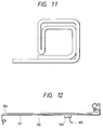
- the upper-end engaging portion was folded back to the inside as shown in Fig. 11, thereby further enhancing the mechanical strength.
- the present example has the effect to reinforce coupling between the lower-end engaging portion and the blind rivet 214 and the effect to enhance the mechanical strength of the upper-end engaging portion and thus achieves the effect to enhance the wind endurance. Therefore, the present example is suitable, especially, for cases wherein the backing 204 is made of a material with low mechanical strength, for example, copper, lead, or a zinc alloy.
- the roof panel in the present example was made in the working width of 200 mm and the length of 1500 mm and in such a way that the amorphous solar battery film-formed on a stainless steel sheet of 0.125 mm was sealed on a copper sheet of 0.8 mm as the backing by the sealing material 0.9 mm thick.
- the sealing material had an adhesive layer of EVA and nonwoven glass fabric and an outermost layer of TEFZEL film of 12.5 ⁇ m.
- the sealing material near the engaging portions had the thickness of 0.45 mm and did not contain the nonwoven glass fabric, taking processability into consideration.
- the horizontal-roofing roof panel in the present example is shown in Fig. 12.
- a steel sheet with very high flexural rigidity is used for the roof backing 101, that the sealing material is not provided near the engaging portions, and that a projected portion and a depressed portion for engagement are provided at the engaging portions.
- Fig. 13 The function will be described with Fig. 13 to show the connected state in the direction of flow of roof. Connection of the upper panel with the lower panel is made by inserting claw 232 into the upper-end engaging portion of the lower panel when mounted and thereafter inserting the projected portion 231 into the depressed portion 230.
- the projected portion 231 when inserted into the depressed portion, expands inside thereof because of its flexural rigidity and thus has the function to further enhance the mechanical strength.
- the upper panel can be turned up after the claw 232 is first disengaged by a catching jig such as a screw driver or the like and then the fitting portion is pulled out by making use of the flexural rigidity. Therefore, the present example has an excellent property to further facilitate the maintenance work.
- the projected portion 231 looks like a recess when seen from the outside, and the projected portion 231 and depressed portion 230 are perforated in the bottom to have drain hole 233, thus realizing the structure to prevent corrosion of roof panel due to intrusion of rain or the like.
- the outer wall of the upper-end engaging portion of the lower panel is structured to strongly contact the lower-end engaging portion of the upper panel as shown in Fig. 13, which constructs the structure very excellent in flashing.
- the roof panel in the present example was the horizontal-roofing roof panel made in the working width of 200 mm and the length of 1500 mm and in such a way that the amorphous solar battery film-formed on the stainless steel sheet of 0.125 mm was sealed on a high-flexural-rigidity steel sheet of 0.20 mm as the roof backing by the sealing material 0.9 mm thick.
- the sealing material had an adhesive layer of EVA and nonwoven glass fabric and an outermost layer of fluororesin film of TEFZEL of 12.5 ⁇ m. The sealing material was not used near the engaging portions, for permitting complex processing of the backing and for maintaining the flexural rigidity.
- FIG. 14 The horizontal-roofing roof panel in this Example 3 is shown in Fig. 14.
- a feature of the present example is that the engaging portion is bent in the opposite direction to that in Example 1, thereby obviating the need for the retaining clip, and
- Fig. 15 shows the connected state of the roof panels of the present example in the flow direction of roof.
- Numeral 240 denotes a screw receiving member for screwing.
- This screw receiving member 240 is bonded to the backing by a known method such as welding or a structural adhesive and the roof panel 209 is fixed to the screw receiving member 240 by screw 241.
- the present example obviates the need for the retaining clip; and because of no need for the retaining clip, no clearance is formed in the portion without the retaining clip and the lower panel thus folded back can be utilized for enhancing adherence with the upper panel, thus realizing an advantage of strong flashing.
- the roof panel in the present example was the horizontal-roofing roof panel made in the working width of 200 mm and the length of 1500 mm and in such a way that the amorphous solar battery film-formed on the stainless steel sheet of 0.125 mm was sealed on a galvanized iron sheet of 0.25 mm as the roof backing by the sealing material 0.9 mm thick.
- the sealing material had an adhesive layer of EVA and nonwoven glass fabric and an outermost layer of TEFZEL film of 12.5 ⁇ m. The sealing material was not used near the upper-end engaging portion, for permitting complicated processing of the backing and for maintaining the flexural rigidity.
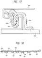
- the horizontal-roofing roof panel in this Example 4 is shown in Fig. 16.
- a feature of the present example is a large recess 108 provided in the upper-end engaging portion, and this recess is used for insertion of retaining clip 206 as shown in Fig. 17.
- Numeral 251 denotes a sealant, which fills the recess between the retaining clip and the roof panel and which functions to prevent intrusion of rain.
- Numeral 250 is a drill screw, which is fixed through the upper panel, the retaining clip, and the lower panel.
- the roof panel since the upper panel is fixed not only to the lower panel but also to the retaining clip for fixing the lower panel by the fastener, the roof panel has extremely high wind endurance.
- Numeral 107 represents buffer members for preventing the combination solar battery and roof panel from being trodden down when stepped on.
- the buffer members may be selected from the known buffer members of polystyrene foam, polyurethane foam, polyethylene foam, or the like and it is also possible to set beams of wood, plastics, or the like along the longitudinal direction of the horizontal-roofing roof.
- the roof panel in the present example was the horizontal-roofing roof panel made in the working width of 275 mm and the length of 1500 mm and in such a way that the amorphous solar battery film-formed on the stainless steel sheet of 0.125 mm was sealed on a galvanized steel sheet of 0.30 mm as the backing by the sealing material 0.9 mm thick.
- the sealant used was a silicone sealant effective in suppressing intrusion of rainwater and strong against thermal degradation or the like.
- the sealing material had an adhesive layer of EVA and nonwoven glass fabric and an outermost layer of TEFZEL film of 12.5 ⁇ m.
- the sealing material was not used near the upper-end engaging portion, for permitting complicated processing of the backing.
- the horizontal-roofing roof panel in this Example 5 is shown in Fig. 18.
- a feature of the present example is that the retaining clip is composed of two constituent members 260 and 261, thus having such structure that, as shown in Fig. 19, the member 260 is engaged with the upper roof panel and functions as flashing and the member 261 is fixed to the sheathing roof board.
- the member 260 has the same width as the roof panel and numeral 361 designates a blind rivet for joining the two members. Since a hole for this rivet has a little play, force of wind to lift the roof 209 is transmitted from the member 260 directly to the member 261 through claw 262. Therefore, as to the wind endurance, the force is received as scattered linearly, which achieves the function capable of greatly enhancing the wind endurance.
- the present example obviates the need for fixing the roof panel by directly perforating the roof panel as in the examples described above, the present example has a great margin for absorbing thermal expansion and contraction specific to the metal roof and facilitates enlargement of one roof panel in the flow direction (in the direction of from the ridge to the eaves). In addition, the present example has a special, functional effect to greatly improve the resistance against metal fatigue or the like.
- Numeral 107 represents buffer members for preventing the roof panel from being trodden down when the combination solar battery and roof panel is stepped on after mounted.
- the buffer members are placed in parallel with the longitudinal direction of the roof panel. Owing to this, the buffer members are not a hindrance while the roof panel is turned up.
- the buffer members may be any known buffer members of polystyrene foam, polyurethane foam, polyethylene foam, or the like and it is also possible to set beams of wood, plastics, or the like along the longitudinal direction of the horizontal-roofing roof.
- the roof panel in the present example was the the horizontal-roofing roof panel made in the working width of 275 mm and the length of 1500 mm and in such a way that the amorphous solar battery film-formed on the stainless steel sheet of 0.125 mm was sealed on a galvanized steel sheet of 0.30 mm as the backing by the sealing material 0.9 mm thick.
- the sealing material had an adhesive layer of EVA and nonwoven glass fabric and an outermost layer of TEFZEL film of 12.5 ⁇ m. Near the engaging portions, the nonwoven glass fabric was excluded for permitting complicated processing of the backing and the thickness of the sealing material was set to be 0.45 mm thinner.
Landscapes
- Engineering & Computer Science (AREA)
- Architecture (AREA)
- Civil Engineering (AREA)
- Structural Engineering (AREA)
- Mechanical Engineering (AREA)
- Roof Covering Using Slabs Or Stiff Sheets (AREA)
- Photovoltaic Devices (AREA)
Applications Claiming Priority (3)
| Application Number | Priority Date | Filing Date | Title |
|---|---|---|---|
| JP246881/96 | 1996-08-30 | ||
| JP8246881A JPH1072910A (ja) | 1996-08-30 | 1996-08-30 | 横葺き屋根板、屋根材一体型太陽電池、横葺き屋根用継ぎ手及び横葺き屋根の施工方法 |
| JP24688196 | 1996-08-30 |
Publications (3)
| Publication Number | Publication Date |
|---|---|
| EP0828036A2 true EP0828036A2 (de) | 1998-03-11 |
| EP0828036A3 EP0828036A3 (de) | 2000-09-27 |
| EP0828036B1 EP0828036B1 (de) | 2006-12-27 |
Family
ID=17155136
Family Applications (1)
| Application Number | Title | Priority Date | Filing Date |
|---|---|---|---|
| EP97114923A Expired - Lifetime EP0828036B1 (de) | 1996-08-30 | 1997-08-28 | Dach und Montagesystem dafür |
Country Status (6)
| Country | Link |
|---|---|
| US (2) | US6155006A (de) |
| EP (1) | EP0828036B1 (de) |
| JP (1) | JPH1072910A (de) |
| KR (1) | KR100276185B1 (de) |
| AU (1) | AU732413B2 (de) |
| DE (1) | DE69737133T2 (de) |
Cited By (17)
| Publication number | Priority date | Publication date | Assignee | Title |
|---|---|---|---|---|
| EP1039549A1 (de) * | 1999-03-19 | 2000-09-27 | Lafarge Braas Roofing Accessories GmbH & Co. | Befestigungssystem für plattenförmige Bauelemente |
| NL1015654C2 (nl) * | 2000-07-07 | 2002-01-08 | Lafarge Dakproducten B V | Indeksamenstel voor indekking tussen pannen op een pannendak. |
| EP0977274A3 (de) * | 1998-07-28 | 2002-05-08 | BP Solarex | Rahmensystem für photovoltaische Module mit integrierten Leitungskanälen |
| EP1187222A3 (de) * | 2000-09-11 | 2004-01-14 | Sanyo Electric Co., Ltd. | Solarzellenmodul |
| EP1112423A4 (de) * | 1998-08-31 | 2004-12-29 | Pacific Solar Pty Ltd | Montagerahmen für paneele und montageverfahren |
| EP1447852A3 (de) * | 2003-02-12 | 2007-05-23 | Sharp Kabushiki Kaisha | Strukturelle Befestigungseinheit zur Installation von quaderförmigen Solarzellenmoduln auf schrägen Dächern |
| FR2923236A1 (fr) * | 2007-11-05 | 2009-05-08 | Imerys Tc Soc Par Actions Simp | Element d'etancheite pour chassis de panneaux et systeme correspondant |
| ES2335169A1 (es) * | 2007-11-16 | 2010-03-22 | Europerfil, S.A | Procedimiento para llevar a cabo el recubrimiento de fachadas y la cobertura ecoenergetica de edificaciones. |
| EP2115236A4 (de) * | 2007-02-08 | 2010-05-12 | Luma Resources Llc | Solarplatten-dachsatz |
| WO2010032063A3 (en) * | 2008-09-19 | 2010-09-02 | Richard David Bankart | Supporting frame for constructing a building including a thermal panel and a photovoltaic panel |
| WO2009086803A3 (de) * | 2008-01-05 | 2011-05-05 | Rev Renewable Energy Ventures, Inc. | Photovoltaikelement, trägerstruktur, verfahren zur montage einer trägerstruktur und kraftwerk dazu |
| FR2963035A1 (fr) * | 2010-07-26 | 2012-01-27 | Joseph Nappo | Systeme d'assemblage de panneaux sur des liteaux d'une toiture |
| WO2018226610A1 (en) * | 2017-06-05 | 2018-12-13 | Tesla, Inc. | Sidelap interconnect for photovoltaic roofing modules |
| US20210265938A1 (en) * | 2018-07-04 | 2021-08-26 | Sabic Global Technologies B.V. | Solar roof forming element, building, and method of forming a roof |
| US11245355B2 (en) | 2018-09-04 | 2022-02-08 | Tesla, Inc. | Solar roof tile module |
| US11245354B2 (en) | 2018-07-31 | 2022-02-08 | Tesla, Inc. | Solar roof tile spacer with embedded circuitry |
| US11437534B2 (en) | 2018-02-20 | 2022-09-06 | Tesla, Inc. | Inter-tile support for solar roof tiles |
Families Citing this family (157)
| Publication number | Priority date | Publication date | Assignee | Title |
|---|---|---|---|---|
| JPH1072910A (ja) * | 1996-08-30 | 1998-03-17 | Canon Inc | 横葺き屋根板、屋根材一体型太陽電池、横葺き屋根用継ぎ手及び横葺き屋根の施工方法 |
| US6393792B1 (en) * | 1998-07-24 | 2002-05-28 | Associated Materials, Incorporated | Splicing member for siding panels |
| ATE467012T1 (de) | 1999-06-09 | 2010-05-15 | Kaneka Corp | Dachziegel mit solarzellenmodul |
| US6452091B1 (en) | 1999-07-14 | 2002-09-17 | Canon Kabushiki Kaisha | Method of producing thin-film single-crystal device, solar cell module and method of producing the same |
| AU6763600A (en) * | 1999-08-11 | 2001-03-05 | Solar Strategies Development, Inc | Mounting apparatus and photovoltaic mounting system for a solar panel and methodof mounting a solar panel |
| JP2001349013A (ja) * | 2000-04-04 | 2001-12-21 | Canon Inc | 外装材および太陽電池モジュール、その製造方法、製造装置および施工方法、並びに建築物および太陽光発電装置 |
| US6553729B1 (en) | 2000-06-09 | 2003-04-29 | United Solar Systems Corporation | Self-adhesive photovoltaic module |
| US6729081B2 (en) | 2000-06-09 | 2004-05-04 | United Solar Systems Corporation | Self-adhesive photovoltaic module |
| US6730841B2 (en) | 2001-03-14 | 2004-05-04 | United Solar Systems Corporation | Method and apparatus for mounting a photovoltaic roofing material |
| US7434362B2 (en) | 2001-07-20 | 2008-10-14 | Unirac, Inc. | System for removably and adjustably mounting a device on a surface |
| US6870087B1 (en) | 2001-09-14 | 2005-03-22 | Patrick Gallagher | Assembly method and apparatus for photovoltaic module |
| JPWO2003029577A1 (ja) * | 2001-09-28 | 2005-01-20 | 株式会社カネカ | 太陽電池モジュール、太陽電池モジュールの敷設方法及び太陽電池モジュールの吹上げ防止装置 |
| JP2003124489A (ja) * | 2001-10-12 | 2003-04-25 | Mitsubishi Heavy Ind Ltd | 太陽電池モジュール集合体、配線システム及び太陽光発電システム |
| US20030154667A1 (en) * | 2002-02-20 | 2003-08-21 | Dinwoodie Thomas L. | Shingle system |
| US7178295B2 (en) | 2002-02-20 | 2007-02-20 | Powerlight Corporation | Shingle assembly |
| US6883290B2 (en) * | 2002-02-20 | 2005-04-26 | Powerlight Corporation | Shingle system and method |
| US20040000334A1 (en) * | 2002-06-27 | 2004-01-01 | Astropower, Inc. | Photovoltaic tiles, roofing system, and method of constructing roof |
| US20040221886A1 (en) * | 2003-02-26 | 2004-11-11 | Kyocera Corporation | Solar cell module and solar cell array using same |
| JP4681806B2 (ja) * | 2003-12-19 | 2011-05-11 | キヤノン株式会社 | 太陽電池モジュール |
| US7592537B1 (en) | 2004-02-05 | 2009-09-22 | John Raymond West | Method and apparatus for mounting photovoltaic modules |
| US20060037280A1 (en) * | 2004-07-30 | 2006-02-23 | Smith Charles L Jr | Metal roof system |
| US20060042683A1 (en) * | 2004-08-31 | 2006-03-02 | Ron Gangemi | System and method for mounting photovoltaic cells |
| JP4991119B2 (ja) * | 2005-03-29 | 2012-08-01 | 京セラ株式会社 | 太陽電池モジュール装置 |
| US7698864B2 (en) * | 2005-07-14 | 2010-04-20 | Atlantis Plastics, Inc. | Bonded siding panels |
| US20070193618A1 (en) * | 2005-09-19 | 2007-08-23 | Solar Roofing Systems, Inc. | Integrated Solar Roofing System |
| US20070107356A1 (en) * | 2005-11-01 | 2007-05-17 | Certainteed Corporation | Staggered look shake siding panel with improved locking mechanism |
| USD643133S1 (en) | 2005-11-01 | 2011-08-09 | Certainteed Corporation | Double rough split shake siding panel |
| DE102006009412A1 (de) * | 2006-02-23 | 2007-08-30 | Zentrum für Sonnenenergie- und Wasserstoff-Forschung Baden-Württemberg | Solarmodulsystem mit Tragstruktur |
| US8074418B2 (en) | 2006-04-13 | 2011-12-13 | Sabic Innovations Plastics IP B.V. | Apparatus for connecting panels |
| US20070243820A1 (en) | 2006-04-18 | 2007-10-18 | O'hagin Carolina | Automatic roof ventilation system |
| GB0610031D0 (en) * | 2006-05-19 | 2006-06-28 | Solar Century Holdings Ltd | Solar panel roof mounting system |
| US20070289249A1 (en) * | 2006-06-16 | 2007-12-20 | David Martel | L-shape slotted deck board and hidden fastener system |
| US8607510B2 (en) * | 2006-10-25 | 2013-12-17 | Gregory S. Daniels | Form-fitting solar panel for roofs and roof vents |
| WO2008083042A2 (en) * | 2006-12-29 | 2008-07-10 | Bp Corporation North America Inc. | Photovoltaic modules with a transparent material having a camouflaged pattern |
| US20080302934A1 (en) * | 2007-03-06 | 2008-12-11 | Robin Nelson | Roofing bracket for supporting a platform |
| FR2914785B1 (fr) * | 2007-04-06 | 2009-05-15 | Saint Gobain Ct Recherches | Revetement de toiture photovoltaique |
| US20080271774A1 (en) | 2007-05-01 | 2008-11-06 | Kalkanoglu Husnu M | Photovoltaic Roofing Wiring Array, Photovoltaic Roofing Wiring System and Roofs Using Them |
| US20080302031A1 (en) * | 2007-06-05 | 2008-12-11 | Solar Roofing Systems, Inc., | Integrated solar roofing tile connection system |
| US20090014058A1 (en) * | 2007-07-13 | 2009-01-15 | Miasole | Rooftop photovoltaic systems |
| US20090014057A1 (en) * | 2007-07-13 | 2009-01-15 | Miasole | Photovoltaic modules with integrated devices |
| FR2919640A1 (fr) * | 2007-08-01 | 2009-02-06 | Tenesol Sa | Profile et dispositif de montage de panneaux photovoltaiques au sein d'une structure de batiment, et notamment d'une toiture, et structure de batiment integrant ces elements |
| US20090056792A1 (en) * | 2007-08-29 | 2009-03-05 | Salyer Ted H | Interconnecting support panel providing substantially planar upper surface |
| US9178465B2 (en) | 2007-11-06 | 2015-11-03 | Certainteed Corporation | Photovoltaic roofing elements including tie layer systems and roofs using them |
| WO2009061939A2 (en) * | 2007-11-06 | 2009-05-14 | Ming-Liang Shiao | Photovoltaic roofing elements including tie layer systems, and roofs using them, and methods for making them |
| WO2009061963A2 (en) | 2007-11-06 | 2009-05-14 | Krause Richard H | Photovoltaic roofing systems and methods for installing them |
| US20090133738A1 (en) * | 2007-11-06 | 2009-05-28 | Ming-Liang Shiao | Photovoltaic Roofing Elements and Roofs Using Them |
| US20100330898A1 (en) * | 2008-02-26 | 2010-12-30 | Daniels Gregory S | Roof ventilation system |
| CN102187159B (zh) | 2008-05-13 | 2014-01-29 | 格雷戈里·S·丹尼尔 | 防余烬及火焰的屋顶通风系统 |
| FR2942253A1 (fr) * | 2009-02-16 | 2010-08-20 | Guy Baret | Element de fixation d'une tuile |
| DE102009010225A1 (de) * | 2009-02-23 | 2010-09-02 | Solon Se | Solaranlage aus zumindest einem Solarmodul mit einer federnden Lagerung der Abdeckplatte |
| US8646228B2 (en) | 2009-03-24 | 2014-02-11 | Certainteed Corporation | Photovoltaic systems, methods for installing photovoltaic systems, and kits for installing photovoltaic systems |
| US9057542B2 (en) * | 2009-04-27 | 2015-06-16 | Unirac, Inc. | Snap-on structural connector |
| US9562356B2 (en) * | 2009-05-13 | 2017-02-07 | Sabic Global Technologies B.V. | Connector assemblies for connecting panels |
| US20100313499A1 (en) * | 2009-06-10 | 2010-12-16 | Gangemi Ronald J | Roof mounting bracket for photovoltaic power generation system |
| US20100313501A1 (en) * | 2009-06-10 | 2010-12-16 | Gangemi Ronald J | Roof mounting bracket for photovoltaic power generation system |
| KR101031246B1 (ko) * | 2009-09-16 | 2011-04-29 | 주성엔지니어링(주) | 박막형 태양전지 및 그 제조방법, 및 그를 이용한 박막형 태양전지 모듈 및 태양광 발전 시스템 |
| KR101045065B1 (ko) | 2009-10-09 | 2011-06-28 | 남성기전 주식회사 | 태양전지 모듈 설치용 구조체 및 이를 포함하는 태양전지 모듈 구조물 |
| US8424256B2 (en) * | 2010-04-01 | 2013-04-23 | Thomas Lawson Cook | Asphalt roof integrated photovoltaic |
| US9334652B2 (en) * | 2010-05-20 | 2016-05-10 | David Plath | Paneling system |
| US8782967B2 (en) | 2010-09-27 | 2014-07-22 | Gregory S. Daniels | Above sheathing ventilation system |
| US8601754B2 (en) * | 2010-12-31 | 2013-12-10 | Certainteed Corporation | Photovoltaic roofing elements and photovoltaic roofing systems |
| US8946600B1 (en) * | 2011-04-28 | 2015-02-03 | Ricky R. Dupuis | Roof de-icing system |
| US8887453B2 (en) * | 2011-05-16 | 2014-11-18 | Hanergy Holding Group Ltd | Supporting structures for building integrable photovoltaic modules |
| US8763316B2 (en) | 2012-03-30 | 2014-07-01 | Sunpower Corporation | Active fire-blocking wind deflector |
| US9074372B2 (en) | 2012-04-26 | 2015-07-07 | Sabic Global Technologies B.V. | Connector assemblies for connecting panels |
| US9312411B2 (en) | 2012-04-26 | 2016-04-12 | Sabic Global Technologies B.V. | Connector assemblies for connecting panels, panels with connector assemblies |
| US8347565B2 (en) * | 2012-06-29 | 2013-01-08 | Min Carroll | Solar panels fixtures and installations |
| MX345219B (es) | 2012-10-01 | 2017-01-20 | Building Materials Invest Corp | Sistema de panel solar en techo con orillas y tratamientos de superficie. |
| US20150275520A1 (en) * | 2012-11-08 | 2015-10-01 | Nippon Steel & Sumikin Coated Sheet Corporation | Horizontal roofing roof structure |
| WO2014134580A1 (en) * | 2013-02-28 | 2014-09-04 | Zep Solar, Inc. | Apparatus, system, and method for photovoltaic-related wire management |
| KR101358899B1 (ko) * | 2013-03-26 | 2014-02-10 | 주식회사 동양지티에스 | 건축물 지붕의 구조물 고정클립 |
| US9394693B2 (en) | 2013-11-22 | 2016-07-19 | Gregory S. Daniels | Roof vent for supporting a solar panel |
| US9531319B2 (en) | 2013-12-23 | 2016-12-27 | Sunpower Corporation | Clamps for solar systems |
| WO2015130742A1 (en) | 2014-02-28 | 2015-09-03 | Sunpower Corporation | Improved end clamps for solar systems |
| USD755944S1 (en) | 2014-03-06 | 2016-05-10 | Gregory S. Daniels | Roof vent assembly |
| AU2014385207B2 (en) | 2014-03-06 | 2019-11-28 | Gregory S. Daniels | Roof vent with an integrated fan |
| USD748239S1 (en) | 2014-03-06 | 2016-01-26 | Gregory S. Daniels | Roof vent assembly |
| US9097021B1 (en) * | 2014-05-17 | 2015-08-04 | John M. Williams | Weather shielding system for slate and tile roofs |
| US11326793B2 (en) | 2018-12-21 | 2022-05-10 | Gregory S. Daniels | Roof vent and roof ventilation system |
| USD930810S1 (en) | 2015-11-19 | 2021-09-14 | Gregory S. Daniels | Roof vent |
| USD891604S1 (en) | 2015-11-19 | 2020-07-28 | Gregory S. Daniels | Roof vent assembly |
| US10749460B2 (en) * | 2016-06-03 | 2020-08-18 | PV Technical Services Inc. | Solar shingle roofing kit |
| US9813015B1 (en) | 2016-06-29 | 2017-11-07 | Sunpower Corporation | End clamp for mounting solar module to rail |
| US20180183382A1 (en) * | 2016-12-27 | 2018-06-28 | David R. Hall | Interlocking Roofing System |
| US10784816B2 (en) * | 2018-12-20 | 2020-09-22 | Hall Labs Llc | Electrical and mechanical roof underlayment |
| US11927017B2 (en) | 2017-06-05 | 2024-03-12 | Millennuim Slate, LLC | Roofing system and method |
| US11578494B2 (en) | 2017-06-05 | 2023-02-14 | Millennium Slate, Llc | Roofing system and method |
| US10829937B2 (en) * | 2017-06-05 | 2020-11-10 | Millennium Slate, Llc | Roofing system and method |
| US10490682B2 (en) | 2018-03-14 | 2019-11-26 | National Mechanical Group Corp. | Frame-less encapsulated photo-voltaic solar panel supporting solar cell modules encapsulated within multiple layers of optically-transparent epoxy-resin materials |
| US11035128B2 (en) * | 2018-03-30 | 2021-06-15 | Certainteed Llc | Exterior cladding panels and methods for installing them |
| CN110374267B (zh) * | 2018-04-13 | 2024-05-24 | 汉瓦技术有限公司 | 一种瓦片和瓦片的制作方法 |
| JP7159625B2 (ja) * | 2018-06-07 | 2022-10-25 | 株式会社オートネットワーク技術研究所 | 回路ユニット、電気接続箱 |
| MX2022006401A (es) | 2019-11-27 | 2022-10-27 | GAF Energy LLC | Módulo fotovoltaico integrado de techo con espaciador. |
| CN110863618A (zh) * | 2019-12-04 | 2020-03-06 | 徐州融创达电子科技有限公司 | 一种便于安装的屋面彩钢瓦结构 |
| US11398795B2 (en) | 2019-12-20 | 2022-07-26 | GAF Energy LLC | Roof integrated photovoltaic system |
| CA3165505A1 (en) | 2020-01-22 | 2021-07-29 | Nathan Peterson | Integrated photovoltaic roofing shingles, methods, systems, and kits thereof |
| US11961928B2 (en) | 2020-02-27 | 2024-04-16 | GAF Energy LLC | Photovoltaic module with light-scattering encapsulant providing shingle-mimicking appearance |
| WO2021183747A1 (en) | 2020-03-13 | 2021-09-16 | Englert, Inc. | Interlocking roofing panel system and method |
| WO2021207238A1 (en) | 2020-04-09 | 2021-10-14 | GAF Energy LLC | Three-dimensional laminate photovoltaic module |
| US11217715B2 (en) | 2020-04-30 | 2022-01-04 | GAF Energy LLC | Photovoltaic module frontsheet and backsheet |
| CA3176241A1 (en) | 2020-05-13 | 2021-11-18 | GAF Energy LLC | Electrical cable passthrough |
| CN115769383A (zh) | 2020-06-04 | 2023-03-07 | Gaf能源有限责任公司 | 光伏屋顶板及其安装方法 |
| WO2022020490A1 (en) | 2020-07-22 | 2022-01-27 | GAF Energy LLC | Photovoltaic modules |
| WO2022035473A1 (en) | 2020-08-11 | 2022-02-17 | GAF Energy LLC | Roof mounted photovoltaic system and method for wireless transfer of electrical energy |
| CN116420231A (zh) | 2020-09-03 | 2023-07-11 | Gaf能源有限责任公司 | 建筑集成光伏系统 |
| USD950481S1 (en) | 2020-10-02 | 2022-05-03 | GAF Energy LLC | Solar roofing system |
| USD950482S1 (en) | 2020-10-02 | 2022-05-03 | GAF Energy LLC | Solar roofing system |
| US11384543B2 (en) | 2020-10-12 | 2022-07-12 | Englert, Inc. | Interlocking roofing panel system and method |
| US11545928B2 (en) | 2020-10-13 | 2023-01-03 | GAF Energy LLC | Solar roofing system |
| EP4229750A4 (de) | 2020-10-14 | 2024-11-13 | Gaf Energy LLC | Montagevorrichtung für fotovoltaische module |
| USD963834S1 (en) | 2020-10-27 | 2022-09-13 | Gregory S. Daniels | Roof vent with a circular integrated fan |
| USD964546S1 (en) | 2020-10-27 | 2022-09-20 | Gregory S. Daniels | Roof vent with a circular integrated fan |
| US11454027B2 (en) | 2020-10-29 | 2022-09-27 | GAF Energy LLC | System of roofing and photovoltaic shingles and methods of installing same |
| US11486144B2 (en) | 2020-11-12 | 2022-11-01 | GAF Energy LLC | Roofing shingles with handles |
| WO2022103841A1 (en) | 2020-11-13 | 2022-05-19 | GAF Energy LLC | Photovoltaic module systems and methods |
| MX2023006559A (es) | 2020-12-02 | 2023-09-18 | GAF Energy LLC | Aletas escalonadas para tejas fotovoltáicas para techos. |
| CA3205363A1 (en) | 2021-01-19 | 2022-07-28 | Thierry Nguyen | Watershedding features for roofing shingles |
| MX2023009726A (es) | 2021-02-19 | 2023-11-09 | GAF Energy LLC | Módulo fotovoltaico para un techo con cinta de fibra continua. |
| US12568694B2 (en) | 2021-03-19 | 2026-03-03 | GAF Energy LLC | Photovoltaic module with a laminated potted printed circuit board |
| MX2023011156A (es) | 2021-03-29 | 2023-10-05 | GAF Energy LLC | Componentes electricos para sitemas fotovoltaicos. |
| MX2023013029A (es) | 2021-05-06 | 2023-11-16 | GAF Energy LLC | Modulo fotovoltaico con bordes perimetrales transparentes. |
| MX2023014362A (es) | 2021-06-02 | 2023-12-15 | GAF Energy LLC | Modulo fotovoltaico con encapsulante de dispersion de la luz que proporciona una apariencia que imita a las tejas. |
| US12009781B2 (en) | 2021-07-06 | 2024-06-11 | GAF Energy LLC | Jumper module for photovoltaic systems |
| US11512480B1 (en) | 2021-07-16 | 2022-11-29 | GAF Energy LLC | Roof material storage bracket |
| CN113802778A (zh) * | 2021-08-25 | 2021-12-17 | 湖南盛德节能环保科技有限公司 | 一种钢结构太阳能光伏防水减震屋顶 |
| US11728759B2 (en) | 2021-09-01 | 2023-08-15 | GAF Energy LLC | Photovoltaic modules for commercial roofing |
| WO2023141566A1 (en) | 2022-01-20 | 2023-07-27 | GAF Energy LLC | Roofing shingles for mimicking the appearance of photovoltaic modules |
| US12013153B2 (en) | 2022-02-08 | 2024-06-18 | GAF Energy LLC | Building integrated photovoltaic system |
| US12209414B2 (en) | 2022-02-23 | 2025-01-28 | GAF Energy LLC | Roofing shingle and method of manufacturing same |
| WO2023173019A1 (en) | 2022-03-10 | 2023-09-14 | GAF Energy LLC | Combined encapsulant and backsheet for photovoltaic modules |
| US12199550B2 (en) | 2022-04-08 | 2025-01-14 | GAF Energy LLC | Low profile connector for solar roofing systems |
| CA3257758A1 (en) | 2022-06-06 | 2023-12-14 | GAF Energy LLC | ACTIVE COMPONENT INDICATORS FOR PHOTOVOLTAIC SYSTEMS |
| US12325996B2 (en) | 2022-07-15 | 2025-06-10 | GAF Energy LLC | Solar roofing system with fiber composite roofing shingles |
| US12145348B2 (en) | 2022-08-24 | 2024-11-19 | GAF Energy LLC | System for forming a roofing membrane, and associated method |
| EP4581684A1 (de) | 2022-08-29 | 2025-07-09 | Gaf Energy LLC | Fotovoltaische module mit versetzten schichten |
| US12034089B2 (en) | 2022-09-01 | 2024-07-09 | GAF Energy LLC | Anti-reflective photovoltaic shingles and related methods |
| WO2024059462A1 (en) | 2022-09-13 | 2024-03-21 | GAF Energy LLC | Sensing roofing system and method thereof |
| US12015374B2 (en) | 2022-09-26 | 2024-06-18 | GAF Energy LLC | Photovoltaic modules integrated with building siding and fencing |
| WO2024073498A1 (en) | 2022-09-29 | 2024-04-04 | GAF Energy LLC | Jumper module with sleeve |
| US12031332B2 (en) | 2022-10-25 | 2024-07-09 | GAF Energy LLC | Roofing materials and related methods |
| US12231075B2 (en) | 2022-10-27 | 2025-02-18 | GAF Energy LLC | Building integrated photovoltaic systems |
| US12413183B2 (en) | 2022-11-15 | 2025-09-09 | GAF Energy LLC | Electrical cable passthrough for photovoltaic systems |
| US11811361B1 (en) | 2022-12-14 | 2023-11-07 | GAF Energy LLC | Rapid shutdown device for photovoltaic modules |
| US12445089B2 (en) | 2023-02-03 | 2025-10-14 | GAF Energy LLC | Photovoltaic module, and associated kit, system, and method |
| US12355390B1 (en) | 2023-02-03 | 2025-07-08 | GAF Energy LLC | Solar shingle and associated roofing system and method |
| US12413174B2 (en) | 2023-02-21 | 2025-09-09 | GAF Energy LLC | Roofing system including photovoltaic module wireway cover, and associated method |
| CA3229888A1 (en) | 2023-02-23 | 2025-04-25 | GAF Energy LLC | Photovoltaic shingles with multi-module power electronics |
| US12506440B2 (en) | 2023-02-28 | 2025-12-23 | GAF Energy LLC | Photovoltaic modules with energy storage components |
| CA3231973A1 (en) | 2023-03-14 | 2025-06-26 | GAF Energy LLC | Integrated cell and circuit interconnection |
| US12009782B1 (en) | 2023-04-04 | 2024-06-11 | GAF Energy LLC | Photovoltaic systems with wireways |
| US12413177B2 (en) | 2023-08-31 | 2025-09-09 | GAF Energy LLC | Photovoltaic modules and roofing shingles with nail zones |
| KR102863259B1 (ko) * | 2023-09-27 | 2025-09-23 | 주식회사 코에스 | 절곡강판 일체형 태양광모듈 조립체 및 그 시공방법 |
| US12451838B1 (en) | 2023-10-06 | 2025-10-21 | GAF Energy LLC | Failsafe functionality for photovoltaic modules |
| WO2025090902A1 (en) | 2023-10-26 | 2025-05-01 | GAF Energy LLC | Roofing systems with water ingress protection |
| WO2025122742A1 (en) | 2023-12-05 | 2025-06-12 | GAF Energy LLC | Roofing system for prevention of roofing shingle deformation |
| WO2025217150A1 (en) | 2024-04-10 | 2025-10-16 | GAF Energy LLC | Roofing shingles with fire retardant structure |
| US12540474B2 (en) | 2024-07-22 | 2026-02-03 | GAF Energy LLC | Electrically grounding metal roofing shingles with photovoltaic systems |
Family Cites Families (49)
| Publication number | Priority date | Publication date | Assignee | Title |
|---|---|---|---|---|
| GB596611A (en) | 1945-06-29 | 1948-01-07 | Automatic Elect Lab | Improvements in or relating to radio direction finders |
| US302113A (en) * | 1884-07-15 | Metal roofing | ||
| US237133A (en) * | 1881-02-01 | Metal roofing | ||
| US1669690A (en) * | 1926-09-27 | 1928-05-15 | Robert B Brandl | Sheet-metal joint |
| GB896611A (en) * | 1958-07-04 | 1962-05-16 | Furrer Josef | Improvements in or relating to a building structure or construction including a plurality of panels, for walls and roofs |
| FR1330174A (fr) * | 1962-04-20 | 1963-06-21 | Profil de recouvrement | |
| US3594028A (en) * | 1969-08-07 | 1971-07-20 | Macomber Inc | Sheet metal joint for panels and sheets |
| DE2160623A1 (de) * | 1971-12-07 | 1973-06-20 | Richard Kellerhoff | Selbsttragende dacheindeckung mit labyrinthdichtung |
| JPS5322430Y2 (de) * | 1974-03-20 | 1978-06-10 | ||
| AU6965674A (en) * | 1974-06-03 | 1975-12-04 | Suzuki Motor Co | Roof plate |
| US4133161A (en) * | 1975-05-01 | 1979-01-09 | Lester Allan G | Panel assemblies and methods of forming same |
| US4122643A (en) * | 1977-02-07 | 1978-10-31 | Hafner Joseph A | Construction panel |
| US4187661A (en) * | 1977-11-28 | 1980-02-12 | Poiry William R | Building siding removal and reinstallation system |
| US4189881A (en) * | 1979-03-12 | 1980-02-26 | Atlantic Richfield Company | Photovoltaic roof construction |
| US4271652A (en) * | 1979-07-23 | 1981-06-09 | Ake Svensson | Facing |
| FR2465315A1 (fr) * | 1979-09-10 | 1981-03-20 | Radiotechnique Compelec | Panneau generateur photovoltaique assurant l'etancheite aux intemperies d'une toiture par pose directe sur la charpente |
| US4353161A (en) * | 1981-06-18 | 1982-10-12 | Atlantic Richfield Company | Process for fabricating solar to electrical energy conversion units |
| US4424655A (en) * | 1981-07-27 | 1984-01-10 | Aluminum Company Of America | Compensating clip for siding |
| US4432181A (en) * | 1981-08-13 | 1984-02-21 | Motokatsu Funaki | Wall construction for architectural structure |
| US4433200A (en) * | 1981-10-02 | 1984-02-21 | Atlantic Richfield Company | Roll formed pan solar module |
| JPS59152670A (ja) * | 1983-02-18 | 1984-08-31 | Shimizu Constr Co Ltd | 起電装置をもつた屋根 |
| US4636577A (en) * | 1983-08-29 | 1987-01-13 | Thomas & Betts Corporation | Solar panel module and support therefor |
| JPS61287278A (ja) * | 1985-06-14 | 1986-12-17 | Takenaka Komuten Co Ltd | 太陽電池付屋根ユニツト |
| JPH02125050A (ja) * | 1988-11-04 | 1990-05-14 | Funaki Shoji Kk | 建築構造物の横葺き外装構造 |
| JP3091868B2 (ja) * | 1989-03-20 | 2000-09-25 | 株式会社チューオー | 屋根材 |
| JP2759279B2 (ja) * | 1989-04-20 | 1998-05-28 | 三洋電機株式会社 | 屋根設置用太陽電池装置 |
| US5092939A (en) * | 1990-11-30 | 1992-03-03 | United Solar Systems Corporation | Photovoltaic roof and method of making same |
| US5164020A (en) * | 1991-05-24 | 1992-11-17 | Solarex Corporation | Solar panel |
| JPH0555618A (ja) * | 1991-08-28 | 1993-03-05 | Sanyo Electric Co Ltd | 太陽電池発電装置 |
| JPH05167095A (ja) * | 1991-12-16 | 1993-07-02 | Tonen Corp | 太陽電池パネル |
| JP2974513B2 (ja) * | 1992-09-03 | 1999-11-10 | キヤノン株式会社 | 屋根材一体型太陽電池モジュール |
| JP2586865B2 (ja) * | 1992-09-03 | 1997-03-05 | キヤノン株式会社 | 屋根材一体型太陽電池及び太陽電池の設置方法 |
| JPH06114111A (ja) * | 1992-10-08 | 1994-04-26 | Toray Monofilament Co Ltd | 医療用ガイドワイヤ |
| JP3260858B2 (ja) * | 1992-10-30 | 2002-02-25 | 京セラ株式会社 | 太陽電池装置 |
| AU669399B2 (en) * | 1992-11-19 | 1996-06-06 | Hirai Engineering Corporation | Roof system utilizing a solar cell |
| US5480494A (en) * | 1993-05-18 | 1996-01-02 | Canon Kabushiki Kaisha | Solar cell module and installation method thereof |
| DE9312518U1 (de) * | 1993-08-20 | 1993-11-25 | Schüren, Julian, 47239 Duisburg | Solarmodul |
| JP3004160B2 (ja) * | 1993-10-21 | 2000-01-31 | 新日軽株式会社 | 屋根上設置型太陽電池装置の雨仕舞装置 |
| JPH07202242A (ja) * | 1993-11-26 | 1995-08-04 | Sanyo Electric Co Ltd | 太陽電池モジュール及び太陽電池装置 |
| US5589006A (en) * | 1993-11-30 | 1996-12-31 | Canon Kabushiki Kaisha | Solar battery module and passive solar system using same |
| JPH07222365A (ja) * | 1994-02-04 | 1995-08-18 | Fuji Electric Co Ltd | 太陽光発電システムの起動方法 |
| JP3507126B2 (ja) * | 1994-04-30 | 2004-03-15 | キヤノン株式会社 | 太陽電池付き横葺き屋根ユニット |
| JP3165606B2 (ja) * | 1994-12-27 | 2001-05-14 | シャープ株式会社 | 太陽電池モジュールの異常チェック機能付連系形太陽光発電装置 |
| JPH09107119A (ja) * | 1995-10-11 | 1997-04-22 | Canon Inc | 太陽電池モジュール及び製造法 |
| US6182403B1 (en) * | 1996-08-30 | 2001-02-06 | Canon Kabushiki Kaisha | Combination solar battery and roof unit and mounting method thereof |
| JPH1072910A (ja) * | 1996-08-30 | 1998-03-17 | Canon Inc | 横葺き屋根板、屋根材一体型太陽電池、横葺き屋根用継ぎ手及び横葺き屋根の施工方法 |
| JP3408074B2 (ja) * | 1996-09-06 | 2003-05-19 | キヤノン株式会社 | 屋根材一体型太陽電池及びその施工方法 |
| JPH11150287A (ja) * | 1997-09-10 | 1999-06-02 | Canon Inc | 太陽電池モジュール、太陽電池付き外囲体、太陽電池付き外囲体の設置方法、及び太陽光発電システム |
| JPH11193613A (ja) * | 1998-01-06 | 1999-07-21 | Canon Inc | 太陽電池モジュール及び太陽電池付き外囲体 |
-
1996
- 1996-08-30 JP JP8246881A patent/JPH1072910A/ja active Pending
-
1997
- 1997-08-21 US US08/915,666 patent/US6155006A/en not_active Expired - Fee Related
- 1997-08-28 EP EP97114923A patent/EP0828036B1/de not_active Expired - Lifetime
- 1997-08-28 DE DE69737133T patent/DE69737133T2/de not_active Expired - Fee Related
- 1997-08-29 AU AU36118/97A patent/AU732413B2/en not_active Ceased
- 1997-08-29 KR KR1019970042546A patent/KR100276185B1/ko not_active Expired - Fee Related
-
2000
- 2000-08-18 US US09/640,751 patent/US6336304B1/en not_active Expired - Fee Related
Cited By (24)
| Publication number | Priority date | Publication date | Assignee | Title |
|---|---|---|---|---|
| EP0977274A3 (de) * | 1998-07-28 | 2002-05-08 | BP Solarex | Rahmensystem für photovoltaische Module mit integrierten Leitungskanälen |
| EP1112423A4 (de) * | 1998-08-31 | 2004-12-29 | Pacific Solar Pty Ltd | Montagerahmen für paneele und montageverfahren |
| WO2000057488A1 (de) * | 1999-03-19 | 2000-09-28 | Lafarge Braas Roofing Accessories Gmbh & Co. | Befestigungssystem für plattenförmige bauelemente |
| EP1039549A1 (de) * | 1999-03-19 | 2000-09-27 | Lafarge Braas Roofing Accessories GmbH & Co. | Befestigungssystem für plattenförmige Bauelemente |
| NL1015654C2 (nl) * | 2000-07-07 | 2002-01-08 | Lafarge Dakproducten B V | Indeksamenstel voor indekking tussen pannen op een pannendak. |
| EP1170806A1 (de) * | 2000-07-07 | 2002-01-09 | Lafarge Dakprodukten B.V. | Abdichtung zum Abdichten zwischen Dachziegeln auf einem Dach |
| EP1187222A3 (de) * | 2000-09-11 | 2004-01-14 | Sanyo Electric Co., Ltd. | Solarzellenmodul |
| EP1447852A3 (de) * | 2003-02-12 | 2007-05-23 | Sharp Kabushiki Kaisha | Strukturelle Befestigungseinheit zur Installation von quaderförmigen Solarzellenmoduln auf schrägen Dächern |
| EP2115236A4 (de) * | 2007-02-08 | 2010-05-12 | Luma Resources Llc | Solarplatten-dachsatz |
| FR2923236A1 (fr) * | 2007-11-05 | 2009-05-08 | Imerys Tc Soc Par Actions Simp | Element d'etancheite pour chassis de panneaux et systeme correspondant |
| ES2335169B1 (es) * | 2007-11-16 | 2011-03-03 | Europerfil, S.A | Procedimiento para llevar a cabo el recubrimiento de fachadas y la cobertura ecoenergetica de edificaciones. |
| ES2335169A1 (es) * | 2007-11-16 | 2010-03-22 | Europerfil, S.A | Procedimiento para llevar a cabo el recubrimiento de fachadas y la cobertura ecoenergetica de edificaciones. |
| WO2009086803A3 (de) * | 2008-01-05 | 2011-05-05 | Rev Renewable Energy Ventures, Inc. | Photovoltaikelement, trägerstruktur, verfahren zur montage einer trägerstruktur und kraftwerk dazu |
| WO2010032063A3 (en) * | 2008-09-19 | 2010-09-02 | Richard David Bankart | Supporting frame for constructing a building including a thermal panel and a photovoltaic panel |
| GB2476210A (en) * | 2008-09-19 | 2011-06-15 | Richard David Bankart | Supporting frame for constructing a building including a thermal panel and a photovoltaic panel |
| FR2963035A1 (fr) * | 2010-07-26 | 2012-01-27 | Joseph Nappo | Systeme d'assemblage de panneaux sur des liteaux d'une toiture |
| US10985688B2 (en) | 2017-06-05 | 2021-04-20 | Tesla, Inc. | Sidelap interconnect for photovoltaic roofing modules |
| WO2018226610A1 (en) * | 2017-06-05 | 2018-12-13 | Tesla, Inc. | Sidelap interconnect for photovoltaic roofing modules |
| US11258398B2 (en) | 2017-06-05 | 2022-02-22 | Tesla, Inc. | Multi-region solar roofing modules |
| US11437534B2 (en) | 2018-02-20 | 2022-09-06 | Tesla, Inc. | Inter-tile support for solar roof tiles |
| US20210265938A1 (en) * | 2018-07-04 | 2021-08-26 | Sabic Global Technologies B.V. | Solar roof forming element, building, and method of forming a roof |
| US11594999B2 (en) * | 2018-07-04 | 2023-02-28 | Sabic Global Technologies B.V. | Solar roof forming element, building, and method of forming a roof |
| US11245354B2 (en) | 2018-07-31 | 2022-02-08 | Tesla, Inc. | Solar roof tile spacer with embedded circuitry |
| US11245355B2 (en) | 2018-09-04 | 2022-02-08 | Tesla, Inc. | Solar roof tile module |
Also Published As
| Publication number | Publication date |
|---|---|
| EP0828036A3 (de) | 2000-09-27 |
| US6155006A (en) | 2000-12-05 |
| EP0828036B1 (de) | 2006-12-27 |
| AU3611897A (en) | 1998-03-05 |
| DE69737133D1 (de) | 2007-02-08 |
| DE69737133T2 (de) | 2007-10-04 |
| KR19980019145A (ko) | 1998-06-05 |
| KR100276185B1 (ko) | 2000-12-15 |
| JPH1072910A (ja) | 1998-03-17 |
| US6336304B1 (en) | 2002-01-08 |
| AU732413B2 (en) | 2001-04-26 |
Similar Documents
| Publication | Publication Date | Title |
|---|---|---|
| US6155006A (en) | Horizontal-roofing and mounting method thereof | |
| US6182403B1 (en) | Combination solar battery and roof unit and mounting method thereof | |
| AU764896B2 (en) | Mounting method for a combination solar battery and roof unit | |
| EP0884432B1 (de) | Sonnendachelement | |
| EP0828034B1 (de) | Sonnenzelle, und Montage- und Herstellungsmethode dafür | |
| JP3937654B2 (ja) | 太陽電池モジュール、その設置方法、ならびにそれを用いた太陽光発電装置および屋根 | |
| AU736617B2 (en) | Solar battery module and roofing material incorporating it | |
| EP0962989A2 (de) | Photovoltaische Leistungserzeugungsvorrichtung | |
| EP0820105A2 (de) | Sonnenzellenmodul und Dachplatte mit Sonnenzellenmodulen | |
| EP0858115A2 (de) | Dachelement mit einer Solarzelle und Einbauverfahren | |
| JP3005123B2 (ja) | 屋根及び太陽電池パネルの設置方法 | |
| JPH07302924A (ja) | 太陽電池付き横葺き屋根ユニット | |
| JPH11204819A (ja) | 太陽光発電装置 | |
| JP2000252510A (ja) | 太陽電池モジュール及びその製造方法、施工方法並びに太陽光発電システム | |
| JP2004197560A (ja) | 建物及び空気流通装置 | |
| AU752106B2 (en) | Horizontal-roofing roof and mounting method therof | |
| JPH10121668A (ja) | 屋根ユニット | |
| JP3787560B2 (ja) | 横葺き屋根及びその施工方法 | |
| JP3787561B2 (ja) | 屋根、その施工方法およびそのメンテナンス方法 | |
| JPH11284216A (ja) | 光起電力素子、太陽電池モジュ―ル、その製造方法、施工方法及び太陽光発電システム | |
| JP2000199302A (ja) | 太陽電池一体型屋根板、その製造方法および施工方法 | |
| JPH11195804A (ja) | 太陽電池モジュール、その製造方法、及びその施工方法 | |
| JP2000336874A (ja) | 屋根材及び太陽電池付屋根材、並びにその製造方法、該屋根材を用いた屋根、太陽光発電装置 |
Legal Events
| Date | Code | Title | Description |
|---|---|---|---|
| PUAI | Public reference made under article 153(3) epc to a published international application that has entered the european phase |
Free format text: ORIGINAL CODE: 0009012 |
|
| AK | Designated contracting states |
Kind code of ref document: A2 Designated state(s): CH DE FR GB IT LI |
|
| AX | Request for extension of the european patent |
Free format text: AL;LT;LV;RO;SI |
|
| PUAL | Search report despatched |
Free format text: ORIGINAL CODE: 0009013 |
|
| AK | Designated contracting states |
Kind code of ref document: A3 Designated state(s): AT BE CH DE DK ES FI FR GB GR IE IT LI LU MC NL PT SE |
|
| AX | Request for extension of the european patent |
Free format text: AL;LT;LV;RO;SI |
|
| 17P | Request for examination filed |
Effective date: 20010206 |
|
| AKX | Designation fees paid |
Free format text: CH DE FR GB IT LI |
|
| 17Q | First examination report despatched |
Effective date: 20030926 |
|
| GRAP | Despatch of communication of intention to grant a patent |
Free format text: ORIGINAL CODE: EPIDOSNIGR1 |
|
| GRAS | Grant fee paid |
Free format text: ORIGINAL CODE: EPIDOSNIGR3 |
|
| GRAA | (expected) grant |
Free format text: ORIGINAL CODE: 0009210 |
|
| AK | Designated contracting states |
Kind code of ref document: B1 Designated state(s): CH DE FR GB IT LI |
|
| PG25 | Lapsed in a contracting state [announced via postgrant information from national office to epo] |
Ref country code: LI Free format text: LAPSE BECAUSE OF FAILURE TO SUBMIT A TRANSLATION OF THE DESCRIPTION OR TO PAY THE FEE WITHIN THE PRESCRIBED TIME-LIMIT Effective date: 20061227 Ref country code: IT Free format text: LAPSE BECAUSE OF FAILURE TO SUBMIT A TRANSLATION OF THE DESCRIPTION OR TO PAY THE FEE WITHIN THE PRESCRIBED TIME-LIMIT;WARNING: LAPSES OF ITALIAN PATENTS WITH EFFECTIVE DATE BEFORE 2007 MAY HAVE OCCURRED AT ANY TIME BEFORE 2007. THE CORRECT EFFECTIVE DATE MAY BE DIFFERENT FROM THE ONE RECORDED. Effective date: 20061227 Ref country code: CH Free format text: LAPSE BECAUSE OF FAILURE TO SUBMIT A TRANSLATION OF THE DESCRIPTION OR TO PAY THE FEE WITHIN THE PRESCRIBED TIME-LIMIT Effective date: 20061227 |
|
| REG | Reference to a national code |
Ref country code: GB Ref legal event code: FG4D |
|
| REF | Corresponds to: |
Ref document number: 69737133 Country of ref document: DE Date of ref document: 20070208 Kind code of ref document: P |
|
| REG | Reference to a national code |
Ref country code: CH Ref legal event code: PL |
|
| EN | Fr: translation not filed | ||
| PLBE | No opposition filed within time limit |
Free format text: ORIGINAL CODE: 0009261 |
|
| STAA | Information on the status of an ep patent application or granted ep patent |
Free format text: STATUS: NO OPPOSITION FILED WITHIN TIME LIMIT |
|
| 26N | No opposition filed |
Effective date: 20070928 |
|
| GBPC | Gb: european patent ceased through non-payment of renewal fee |
Effective date: 20070828 |
|
| PG25 | Lapsed in a contracting state [announced via postgrant information from national office to epo] |
Ref country code: FR Free format text: LAPSE BECAUSE OF FAILURE TO SUBMIT A TRANSLATION OF THE DESCRIPTION OR TO PAY THE FEE WITHIN THE PRESCRIBED TIME-LIMIT Effective date: 20070817 |
|
| PGFP | Annual fee paid to national office [announced via postgrant information from national office to epo] |
Ref country code: DE Payment date: 20080831 Year of fee payment: 12 |
|
| PG25 | Lapsed in a contracting state [announced via postgrant information from national office to epo] |
Ref country code: GB Free format text: LAPSE BECAUSE OF NON-PAYMENT OF DUE FEES Effective date: 20070828 Ref country code: FR Free format text: LAPSE BECAUSE OF FAILURE TO SUBMIT A TRANSLATION OF THE DESCRIPTION OR TO PAY THE FEE WITHIN THE PRESCRIBED TIME-LIMIT Effective date: 20061227 |
|
| PG25 | Lapsed in a contracting state [announced via postgrant information from national office to epo] |
Ref country code: DE Free format text: LAPSE BECAUSE OF NON-PAYMENT OF DUE FEES Effective date: 20100302 |