EP0828045A2 - Umstellbares Doppelbartschloss - Google Patents
Umstellbares Doppelbartschloss Download PDFInfo
- Publication number
- EP0828045A2 EP0828045A2 EP97115227A EP97115227A EP0828045A2 EP 0828045 A2 EP0828045 A2 EP 0828045A2 EP 97115227 A EP97115227 A EP 97115227A EP 97115227 A EP97115227 A EP 97115227A EP 0828045 A2 EP0828045 A2 EP 0828045A2
- Authority
- EP
- European Patent Office
- Prior art keywords
- locking mechanism
- management
- customer
- key
- bolt
- Prior art date
- Legal status (The legal status is an assumption and is not a legal conclusion. Google has not performed a legal analysis and makes no representation as to the accuracy of the status listed.)
- Granted
Links
- 230000007246 mechanism Effects 0.000 claims abstract description 32
- 238000006243 chemical reaction Methods 0.000 abstract description 2
- 238000000034 method Methods 0.000 description 2
- 230000000694 effects Effects 0.000 description 1
Images



Classifications
-
- E—FIXED CONSTRUCTIONS
- E05—LOCKS; KEYS; WINDOW OR DOOR FITTINGS; SAFES
- E05B—LOCKS; ACCESSORIES THEREFOR; HANDCUFFS
- E05B35/00—Locks for use with special keys or a plurality of keys ; keys therefor
- E05B35/08—Locks for use with special keys or a plurality of keys ; keys therefor operable by a plurality of keys
- E05B35/083—Locks for use with special keys or a plurality of keys ; keys therefor operable by a plurality of keys with changeable combination
-
- E—FIXED CONSTRUCTIONS
- E05—LOCKS; KEYS; WINDOW OR DOOR FITTINGS; SAFES
- E05B—LOCKS; ACCESSORIES THEREFOR; HANDCUFFS
- E05B23/00—Locks with lamelliform tumblers which are not set by the insertion of the key and in which the tumblers follow the movement of the bolt
-
- E—FIXED CONSTRUCTIONS
- E05—LOCKS; KEYS; WINDOW OR DOOR FITTINGS; SAFES
- E05B—LOCKS; ACCESSORIES THEREFOR; HANDCUFFS
- E05B35/00—Locks for use with special keys or a plurality of keys ; keys therefor
- E05B35/08—Locks for use with special keys or a plurality of keys ; keys therefor operable by a plurality of keys
- E05B35/12—Locks for use with special keys or a plurality of keys ; keys therefor operable by a plurality of keys requiring the use of two keys, e.g. safe-deposit locks
- E05B35/125—Locks for use with special keys or a plurality of keys ; keys therefor operable by a plurality of keys requiring the use of two keys, e.g. safe-deposit locks with changeable combination
Definitions
- the invention relates to a double bit lock for cupboards and valuables with one convertible customer locking mechanism and an also convertible Management locking mechanism.
- the customer locking mechanism controls the main bolt, the Management locking mechanism an auxiliary bolt that a diverter slide for the Customer locking mechanism.
- a convertible locking system with the above-mentioned features has become known from European patent 0 352 441.
- the auxiliary key and thus the changeover key are withdrawn with the management key.
- the management key is then turned back 180 ° and removed to lock the new coding.
- the customer key is turned further to the right to open the cabinet, or it is turned to the left and removed to fully extend the bolt.
- the cabinet door must first be opened with the appropriate customer key so that a change lever can be reached on the rear of the lock housing. With this lever, the changeover catch is released from the tumblers. Then you insert the new management key and turn it 90 ° to the right to re-code the tumblers.
- the coding is now locked by resetting the changeover lever.
- the cabinet door can then be locked. Both keys must then be removed.
- the well-known locking system has the disadvantage that a possibly necessary re-coding the management locks on occupied cupboards the presence of the tenants because your keys are needed to open the doors. This can be very time-consuming, as there are many tenants for a safe or safe deposit box system belong who want to open their closet at very different times.
- the invention is based, to make the operation of the system much more customer-friendly even in the event of a problem. According to the invention, this is achieved in that under the auxiliary lock of the management locking mechanism there is a changeover catch with a cutting edge which is lifted from the management key via a control recess when the key is turned through 180 °.
- it is sufficient to insert the previously valid management key, turn it 180 ° to the right, pull it out, insert another key offset by 180 ° and turn it half a turn to the left.
- the coding is lost when the key is turned to the left the "tumblers are rearranged.
- the key bit then pushes the locking edge into the toothing of the tumblers in order to secure the new coding.
- the customer's locking mechanism and cabinet door do not need to be opened.
- Fig. 1 denotes the lock housing, which, as usual, has a few spikes and guide grooves for the functional parts in addition to four fastening holes at the corners.
- the left side wall of the lock housing 1 has an opening 1a through which the main bolt 8 passes.
- a closing stop 2 is pivotally mounted.
- a changeover latch 3 has a control recess 3a and a latching cutting edge 3b. This changeover catch is slidably mounted under an auxiliary bolt 4 and is controlled by the beard of the management key.
- the auxiliary bolt 4 has a control recess 4a, a tour pin 4b and a recess 4c.
- a forced tumbler 5 and a tumbler package 6 are mounted on the auxiliary bolt 4.
- the customer locking mechanism includes a changeover catch 7, the main bolt 8, a swivel 9, a forced locking device 10 and a locking device package 11.
- the changeover catch 7 has a mandrel 7a which rests in the recess 7b of the auxiliary bolt 4. Furthermore, a locking cutting edge 7b and control prisms 7c, 7d are provided which act on the tumbler package 11.
- the main bolt 8 shows a bolt head 8a, a control recess 8b and a tour pin 8c.
- the vortex 9 is pivotally mounted on the housing base. It serves to convert the path of the key bit into a larger bolt deflection.
- the functional parts of the castle are protected and held together by a castle ceiling 12. Double-bit keyholes 12a, 12b are machined into the lock cover 12.
- Fig. 2 shows the main bolt 8 and the auxiliary bolt 4 in the locked position.
- the closing stop 2 assumes the rest position.
- the changeover catch 7 is mounted under the main bolt 8. It can be seen that the control prisms 7c, 7d are guided in slots in the main bolt 8.
- the tour pins 4b and 8c abut the front side of the tumbler packages 6 and 11. Both bolts 4 and 8 are therefore blocked.
- FIG. 3 shows how the auxiliary bolt 4 was pushed to the right by a management key 13.
- the tour pin 4b is located in the tour pin channels of the tumbler package 6.
- the closing stop 2 was pivoted down over the control slot of the auxiliary bolt 4. His nose 2a is now in front of a hook stop 8d of the main bolt 8. It can be seen that the auxiliary bolt 4 has pulled the changeover catch 7 over the mandrel 7a, so that the locking cutting edge 7b has come loose from the teeth of the tumbler package 11.
- the tumblers have slipped down with their right end, the coding has been rejected.
- the tumblers were arranged symmetrically on the left side by the control prisms 7c, 7d.
- FIG. 5 shows how the re-coding of a customer key 14 was ended: by turning back the management key, the auxiliary bolt 4 was pushed to the left, the closing stop 2 was pivoted back and the change-over catch 7 was brought into the locking position.
- the customer key 14 can now be turned to the left and withdrawn, or it can be turned to the right to open the cabinet.
- Fig. 2 - 5 has been described as one - for example, when tenants change or loss of key - surrounded the customer locking mechanism.
- all management locks in a safe deposit system will be changed at once.
- the change in customer locks then takes a long time, depending on the random appearance of the tenants or customers.
- the new lock is to be used in cupboard systems for leisure facilities, it is combined with a coin cashier or a coin deposit unit.
- the main bolt is equipped with a mandrel that protrudes from a slot 1b in the lock housing and engages in the additional unit. This ensures that the main bolt can only be extended and the key removed if the tenant has paid the rental price beforehand. When the compartment is emptied, the key remains trapped.
- the lock is combined with a coin deposit unit, the actual rental process is free of charge. However, it is achieved that the tenant leaves the compartment open and with the key trapped if he wants the deposit back.
- the management key is exchanged in a coin-operated cashier or deposit system, you can of course move the customer key to the 90 ° position on all open compartments in order to receive the coding of the customer lock when operating the management lock.
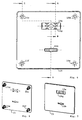
- Fig. 6 the lock fitting 15 is shown in the view from the front. It has an upper keyhole 15a for the management key and a lower keyhole 15b for the customer key.
- the rear threaded sleeves 15c, 15d, 15e, 15f are indicated with broken lines.
- a recess 15g is provided, into which a name plate, a trademark or a license plate can be inserted for camouflage.
- Fig. 8 is a rear perspective view.
- FIG. 9 shows a partial section along the line AB in FIG. 6 .
- Fig. 10 shows a section along the line CD again.
- 11 is an example of a license plate 16 held in the recess 15g by spring pins or the like.
- Fig. 12 the fitting 15 is shown again from a different perspective.
- the new lock system with convertible customer locking mechanism and convertible management locking mechanism is very well suited to be used in closet systems in the sports and leisure sector, where frequently changing users can be expected. It is also suitable for workers' changing rooms, e.g. shift workers or part-time employees, in order to be able to use the cupboards several times during the 24-hour day.
- the invention enables the management locking mechanisms to be changed over in the shortest possible time and without involving the respective cabinet users.
- the opening and conversion of customer locking systems, for example in the event of key loss, does not pose any problems.
Landscapes
- Lock And Its Accessories (AREA)
- Coin-Freed Apparatuses For Hiring Articles (AREA)
Abstract
Bei den bekannten Systemen ist es erforderlich, daß zur Umstellung des Managementschließwerkes die Schranktür geöffnet und ein aus dem Schloßgehäuse austretender Hebel umgelegt wird.
Aufgabe der Erfindung ist es, die Umstellung des Managementschließwerkes so zu gestalten, daß dazu der Schrank nicht geöffnet werden muß.
Dies gelingt dadurch, daß under dem Hilfsriegel (4) des Managementschließwerkes eine Umstellraste (3) mit Rastschneide (3b) gelagert ist, die über eine Steueraussparung (3a) vom Managementschlüssel (13) ausgehoben wird, wenn man den Schlüssel um 180° dreht.
Description
Zur Umstellung des Kundenschließwerkes auf einen neuen Kundenschlüssel wird mit dem Managementschlüssel der Hilfsriegel und damit der Umstellschlüssel zurückgezogen. Dann führt man einen beliebig codierten Kundenschlüssel ein und dreht ihn um 90°, um die Zuhaltungen zu ordnen. Anschließend wird der Managementschlüssel um 180° zurückgedreht und abgezogen, um die Neucodierung zu arretieren. Zum Schluß wird der Kundenschlüssel weiter nach rechts gedreht, um den Schrank zu öffnen, oder er wird nach links gedreht und abgezogen, um den Riegel voll auszufahren.
Zur Umstellung des Managementschlosses muß zuerst mit dem passenden Kundenschlüssel die Schranktür geöffnet werden, damit man an der Rückseite des Schloßgehäuses einen Umstellhebel erreichen kann. Mit diesem Hebel wird die Umstellraste von den Zuhaltungen gelöst. Anschließend führt man den neuen Managementschlüssel ein und dreht ihn um 90° nach rechts, um die Zuhaltungen neu zu codieren. Durch Rückstellung des Umstellhebels wird nunmehr die Codierung arretiert. Danach kann die Schranktür verschlossen werden. Beide Schlüssel sind dann abzuziehen.
Erfindungsgemäß gelingt dies dadurch, daß unter dem Hilfsriegel des Managementschließwerkes eine Umstellraste mit Rastschneide gelagert ist, die über eine Steueraussparung vom Managementschlüssel ausgehoben wird, wenn man den Schlüssel um 180° dreht.
Zur Umstellung des Managementschließwerkes genügt es, daß man den bisher gültigen Managementschlüssel einführt, um 180° nach rechts dreht, abzieht, einen anderen Schlüssel um 180° versetzt einsteckt und eine halbe Umdrehung nach links ausführt. Bei der Rechtsdrehung des

Anschließend schiebt der Schlüsselbart die Rastschneide in die Verzahnung der Zuhaltungen, um die Neucodierung zu sichern.
Bei diesem Umstellvorgang brauchen Kundenschließwerk und Schranktür nicht geöffnet zu werden.
- Fig. 1
- zeigt eine Explosionszeichnung des Schlosses,
- Fig. 2 - 5
- den Hauptriegel, den Hilfsriegel und andere Funktionsteile in verschiedenen Positionen,
- Fig. 6
- einen Schloßbeschlag von vom,
- Fig. 7
- diesen Beschlag in der Perspektive,
- Fig. 8
- eine Perspektivansicht von hinten,
- Fig. 9
- einen Teilschnitt von der Seite,
- Fig. 10
- einen Vertikalschnitt des Beschlages,
- Fig. 11
- ein Schild zum Verdecken des oberen Schlüsselloches,
- Fig. 12
- den Beschlag mit angegossenen Gewindehülsen.
Die linke Seitenwand des Schloßgehäuses 1 hat eine Öffnung 1a, durch die der Hauptriegel 8 hindurchtritt.
Am Boden des Gehäuses 1 ist ein Schließanschlag 2 schwenkbar gelagert.
Eine Umstellraste 3 weist eine Steueraussparung 3a und eine Rastschneide 3b auf. Diese Umstellraste ist unter einem Hilfsriegel 4 verschiebbar gelagert und wird durch den Bart des Managementschlüssels gesteuert.
Der Hilfsriegel 4 hat eine Steueraussparung 4a, einen Tourstift 4b und eine Aussparung 4c. Auf dem Hilfsriegel 4 ist eine Zwangszuhaltung 5 und ein Zuhaltungspaket 6 gelagert. Die Teile 3 - 6 bilden das Managementschließwerk.
Zum Kundenschließwerk gehört eine Umstellraste 7, der Hauptriegel 8, ein Wirbel 9, eine Zwangszuhaltung 10 und ein Zuhaltungspaket 11.
Die Umstellraste 7 weist einen Dorn 7a auf, der in der Aussparung 7b des Hilfsriegels 4 ruht. Ferner sind eine Rastschneide 7b und Steuerprismen 7c, 7d vorgesehen, die auf das Zuhaltungspaket 11 einwirken.
Der Hauptriegel 8 zeigt einen Riegelkopf 8a, eine Steueraussparung 8b und einen Tourstift 8c.
Der Wirbel 9 ist am Gehäuseboden schwenkbar gelagert. Er dient dazu, den Weg des Schlüsselbartes in eine größere Riegelauslenkung umzusetzen.
Die Funktionsteile des Schlosses werden durch eine Schloßdecke 12 geschützt und zusammengehalten. In die Schloßdecke 12 sind Doppelbartschlüssellöcher 12a, 12b eingearbeitet.
Da aber der Hilfsriegel 4 mit der Umstellraste 7 des Kundenschließwerkes gekoppelt ist, geht beim Wechsel des Managementschlüssels auch die Codierung des Zuhaltungspaketes 11 verloren. Dieser durchaus erwünschte Effekt zeigt dem Mieter an, daß eine Umstellung stattgefunden hat. Der Mieter erfährt entweder durch Aushang oder den erfolglosen Aufschließversuch von der Umstellung und erhält dann einen neuen Schlüssel, der in seinem Beisein in das umzucodierende Schloß eingeführt wird.
In der Praxis wird man alle Managementschlösser einer Mietfachanlage auf einmal umstellen. Die Umstellung der Kundenschlösser zieht sich dann über längere Zeit hin, abhängig von dem zufälligen Auftauchen der Mieter oder Kunden.
Auf diesem Wege wird erreicht, daß der Hauptriegel nur ausgefahren und der Schlüssel abgezogen werden kann, wenn der Mieter vorher den Mietpreis entrichtet hat. Wenn das Fach geleert ist, bleibt der Schlüssel gefangen.
Wird das Schloß mit einer Münzpfandeinheit kombiniert, ist der eigentliche Mietvorgang kostenlos. Es wird jedoch erreicht, daß der Mieter das Fach offen und mit gefangenem Schlüssel zurückläßt, wenn er das Pfand zurück haben will.
Wenn in einer Münzkassier- oder -pfandanlage der Managementschlüssel ausgetauscht wird, kann man selbstverständlich an allen offenen Fächern den Kundenschlüssel in die 90°-Position bringen, um beim Bedienen des Managementverschlusses die Codierung des Kundenverschlusses zu erhalten.
Im Bereich des oberen Schlüsselloches 15a ist eine Vertiefung 15g vorgesehen, in die zur Tarnung ein Namensschild, ein Warenzeichen oder ein Nummernschild eingesetzt werden kann.
Fig. 8 eine perspektivische Ansicht von hinten.
Die Erfindung ermöglicht es, mit geringstem Zeitaufwand und ohne Hinzuziehung der jeweiligen Schrankbenutzer die Managementschließwerke umzustellen.
Auch die Öffnung und Umstellung von Kundenschließwerken, z.B. bei Schlüsselverlust, bereitet keine Probleme.
- 1
- Schloßgehäuse
- 1a
- Öffnung
- 2
- Schließanschlag
- 2a
- Nase
- 3
- Umstellraste
- 3a
- Steueraussparung
- 3b
- Rastschneide
- 4
- Hilfsriegel
- 4a
- Steueraussparung
- 4b
- Tourstift
- 4c
- Aussparung
- 5
- Zwangszuhaltung
- 6
- Zuhaltungspaket des Managementschließwerkes
- 7
- Umstellraste
- 7a
- Dorn
- 7b
- Rastschneide
- 7c, 7d
- Steuerprismen
- 8
- Hauptriegel
- 8a
- Riegelkopf
- 8b
- Steueraussparung
- 8c
- Tourstift
- 8d
- Hakenanschlag
- 9
- Wirbel
- 10
- Zwangszuhaltung
- 11
- Zuhaltungspaket des Kundenschließwerkes
- 12
- Schloßdecke
- 12a, 12b
- Schlüssellöcher
- 13
- Managementschlüssel
- 14
- Kundenschlüssel
- 15
- Schloßbeschlag
- 15a, 15b
- Schlüssellöcher
- 15c, 15d, 15e, 15f
- Gewindehülsen
- 15g
- Vertiefung
- 16
- Nummernschild
Claims (6)
- Doppelbartschloß für Schränke und Wertbehälter mit einem umstellbaren Kundenschließwerk, das den Hauptriegel steuert, und einem umstellbaren Managementschließwerk, dessen Hilfsriegel eine Umstellraste des Kundenschließwerkes betätigt,
dadurch gekennzeichnet,daß unter dem Hilfsriegel (4) des Managementschließwerkes eine Umstellraste (3) mit Rastschneide (3b) gelagert ist, die über eine Steueraussparung (3a) vom Managementschlüssel (13) ausgehoben wird, wenn man den Schlüssel um 180° dreht. - Doppelbartschloß nach Anspruch 1, dadurch gekennzeichnet,daß unter dem Hauptriegel (8) eine Umstellraste (7) gelagert ist, die auf das Zuhaltungspaket (11) des Kundenschließwerkes einwirkt und von dem Hilfsriegel (4) bewegt wird unddaß ein vom Hilfsriegel (4) gesteuerter Schließanschlag (2) vorgesehen ist, der während der Umcodierung des Kundenschließwerkes den Rückzug des Hauptriegels (8) begrenzt.
- Doppelbartschloß nach Anspruch 1, dadurch gekennzeichnet,daß der Schließanschlag (2) am Gehäuseboden schwenkbar gelagert ist und durch eine Steuerkurve des Hilfsriegels (4) vor eine Schneide des Hauptriegels (8) bewegt wird.
- Doppelbartschloß nach Anspruch 2, dadurch gekennzeichnet,daß die Umstellraste (7) außer einer Rastschneide (7b) zwei Steuerprismen (7c, 7d) aufweist, die bei der Umcodierung des Kundenschließwerkes die Zuhaltungen (11) auf dem Tourstift (8c) einjustieren.
- Doppelbartschloß nach Anspruch 1, dadurch gekennzeichnet,daß die Rastschneide (3b) des Managementschließwerkes später entkuppelt als die Rastschneide (7b) des Kundenschließwerkes.
- Doppelbartschloß nach Anspruch 1 und den folgenden, dadurch gekennzeichnet,daß das mit der Wertbehältertür verschraubte Schloß einen mit den Schlüssellöchern (15a, 15b) versehenen Schloßbeschlag (15) trägt unddaß das Schlüsselloch (15a) für den Managementschlüssel (13) durch ein abnehmbares Nummernschild (16) verdeckt ist.
Applications Claiming Priority (2)
| Application Number | Priority Date | Filing Date | Title |
|---|---|---|---|
| DE19636444 | 1996-09-07 | ||
| DE19636444A DE19636444A1 (de) | 1996-09-07 | 1996-09-07 | Umstellbares Doppelbartschloß |
Publications (3)
| Publication Number | Publication Date |
|---|---|
| EP0828045A2 true EP0828045A2 (de) | 1998-03-11 |
| EP0828045A3 EP0828045A3 (de) | 1999-05-26 |
| EP0828045B1 EP0828045B1 (de) | 2003-07-02 |
Family
ID=7804967
Family Applications (1)
| Application Number | Title | Priority Date | Filing Date |
|---|---|---|---|
| EP97115227A Expired - Lifetime EP0828045B1 (de) | 1996-09-07 | 1997-09-03 | Umstellbares Doppelbartschloss |
Country Status (3)
| Country | Link |
|---|---|
| EP (1) | EP0828045B1 (de) |
| DE (2) | DE19636444A1 (de) |
| ES (1) | ES2202526T3 (de) |
Families Citing this family (1)
| Publication number | Priority date | Publication date | Assignee | Title |
|---|---|---|---|---|
| DE20308168U1 (de) * | 2003-05-20 | 2004-09-30 | Erwin Renz Metallwarenfabrik Gmbh & Co Kg | Warenzustellbox |
Family Cites Families (2)
| Publication number | Priority date | Publication date | Assignee | Title |
|---|---|---|---|---|
| DE565027C (de) * | 1930-07-02 | 1932-11-25 | Bauer A G | Schloss mit Moeglichkeit des Schliessens mittels eines beliebig zu waehlenden Schluessels einer Schluesselreihe |
| DE3825222A1 (de) * | 1988-07-25 | 1990-02-01 | Mauer Gmbh | Umstellbare schliessanlage |
-
1996
- 1996-09-07 DE DE19636444A patent/DE19636444A1/de not_active Withdrawn
-
1997
- 1997-09-03 DE DE59710367T patent/DE59710367D1/de not_active Expired - Fee Related
- 1997-09-03 ES ES97115227T patent/ES2202526T3/es not_active Expired - Lifetime
- 1997-09-03 EP EP97115227A patent/EP0828045B1/de not_active Expired - Lifetime
Also Published As
| Publication number | Publication date |
|---|---|
| EP0828045B1 (de) | 2003-07-02 |
| DE59710367D1 (de) | 2003-08-07 |
| DE19636444A1 (de) | 1998-03-12 |
| EP0828045A3 (de) | 1999-05-26 |
| ES2202526T3 (es) | 2004-04-01 |
Similar Documents
| Publication | Publication Date | Title |
|---|---|---|
| DE1584262B1 (de) | Verriegelungseinrichtung fuer Tresore | |
| EP0234510B1 (de) | Safe mit durch Münzeinwurf freizugebender Schliessfunktion eines Permutationsschlosses | |
| DE10321455B3 (de) | Depot-Fach-Vorrichtung | |
| EP0828045B1 (de) | Umstellbares Doppelbartschloss | |
| EP0838567B1 (de) | Elektrisch gesteuertes Wertfachschloss | |
| DE1584263B1 (de) | Verriegelungseinrichtung fuer Tresore | |
| DE2912253A1 (de) | Schliessfach mit rueckseitig angeordnetem schloss | |
| EP0352441B1 (de) | Umstellbare Schliessanlage | |
| DE19849704C1 (de) | Koffer-Tresor-System | |
| DE29806298U1 (de) | Vorrichtung zur gesicherten Aufbewahrung und zur individuellen Ausgabe einer Mehrzahl von Gegenständen | |
| EP0268328A2 (de) | Umstellbares Schloss | |
| EP0773338B1 (de) | Umstellbares Doppelbartschloss | |
| DE532019C (de) | Auswechselbarer Postschliessfach-Einsatzkasten | |
| DE69622296T2 (de) | Vandalismussicherer Schrank und Schlossschutzeinrichtung | |
| DE9407802U1 (de) | Fächereinheit | |
| CH646002A5 (de) | Muenzbetaetigte verschliessvorrichtung fuer abschliessbare kaesten, schraenke oder behaelter. | |
| DE530346C (de) | Anlage zur Ausgabe von Geldbetraegen oder Wertsachen nach dem Kassenschluss von Banken u. dgl. | |
| DE1584262C (de) | Verriegelungseinrichtung für Tresore | |
| EP0957221A2 (de) | Zugangstürschloss | |
| DE578616C (de) | Auswechselbares Sicherheitsschloss fuer Wertfaecher | |
| DE9202589U1 (de) | Hotelsafe mit herausnehmbarem Schloß | |
| CH673311A5 (de) | ||
| AT58098B (de) | Einrichtung für den automatischen Verkauf verschiedenartiger Waren. | |
| DE2110254C3 (de) | Verriegelungsvorrichtung für Garderobenkästen od.dgl. mit Münzkassiereinrichtung | |
| DE9001310U1 (de) | Panzerschrank mit gesicherter Geldschleuse |
Legal Events
| Date | Code | Title | Description |
|---|---|---|---|
| PUAI | Public reference made under article 153(3) epc to a published international application that has entered the european phase |
Free format text: ORIGINAL CODE: 0009012 |
|
| AK | Designated contracting states |
Kind code of ref document: A2 Designated state(s): DE ES FR GB IT |
|
| AX | Request for extension of the european patent |
Free format text: AL;LT;LV;RO;SI |
|
| PUAL | Search report despatched |
Free format text: ORIGINAL CODE: 0009013 |
|
| AK | Designated contracting states |
Kind code of ref document: A3 Designated state(s): AT BE CH DE DK ES FI FR GB GR IE IT LI LU MC NL PT SE |
|
| AX | Request for extension of the european patent |
Free format text: AL;LT;LV;RO;SI |
|
| 17P | Request for examination filed |
Effective date: 19990917 |
|
| AKX | Designation fees paid |
Free format text: DE ES FR GB IT |
|
| 17Q | First examination report despatched |
Effective date: 20010802 |
|
| RAP1 | Party data changed (applicant data changed or rights of an application transferred) |
Owner name: KABA MAUER GMBH |
|
| GRAH | Despatch of communication of intention to grant a patent |
Free format text: ORIGINAL CODE: EPIDOS IGRA |
|
| GRAH | Despatch of communication of intention to grant a patent |
Free format text: ORIGINAL CODE: EPIDOS IGRA |
|
| GRAA | (expected) grant |
Free format text: ORIGINAL CODE: 0009210 |
|
| AK | Designated contracting states |
Designated state(s): DE ES FR GB IT |
|
| REG | Reference to a national code |
Ref country code: GB Ref legal event code: FG4D Free format text: NOT ENGLISH |
|
| REF | Corresponds to: |
Ref document number: 59710367 Country of ref document: DE Date of ref document: 20030807 Kind code of ref document: P |
|
| PGFP | Annual fee paid to national office [announced via postgrant information from national office to epo] |
Ref country code: GB Payment date: 20030808 Year of fee payment: 7 |
|
| PGFP | Annual fee paid to national office [announced via postgrant information from national office to epo] |
Ref country code: ES Payment date: 20030828 Year of fee payment: 7 |
|
| GBT | Gb: translation of ep patent filed (gb section 77(6)(a)/1977) |
Effective date: 20031021 |
|
| REG | Reference to a national code |
Ref country code: ES Ref legal event code: FG2A Ref document number: 2202526 Country of ref document: ES Kind code of ref document: T3 |
|
| ET | Fr: translation filed | ||
| PLBE | No opposition filed within time limit |
Free format text: ORIGINAL CODE: 0009261 |
|
| STAA | Information on the status of an ep patent application or granted ep patent |
Free format text: STATUS: NO OPPOSITION FILED WITHIN TIME LIMIT |
|
| 26N | No opposition filed |
Effective date: 20040405 |
|
| PG25 | Lapsed in a contracting state [announced via postgrant information from national office to epo] |
Ref country code: GB Free format text: LAPSE BECAUSE OF NON-PAYMENT OF DUE FEES Effective date: 20040903 |
|
| PG25 | Lapsed in a contracting state [announced via postgrant information from national office to epo] |
Ref country code: ES Free format text: LAPSE BECAUSE OF NON-PAYMENT OF DUE FEES Effective date: 20040904 |
|
| GBPC | Gb: european patent ceased through non-payment of renewal fee |
Effective date: 20040903 |
|
| PG25 | Lapsed in a contracting state [announced via postgrant information from national office to epo] |
Ref country code: IT Free format text: LAPSE BECAUSE OF NON-PAYMENT OF DUE FEES;WARNING: LAPSES OF ITALIAN PATENTS WITH EFFECTIVE DATE BEFORE 2007 MAY HAVE OCCURRED AT ANY TIME BEFORE 2007. THE CORRECT EFFECTIVE DATE MAY BE DIFFERENT FROM THE ONE RECORDED. Effective date: 20050903 |
|
| PGFP | Annual fee paid to national office [announced via postgrant information from national office to epo] |
Ref country code: DE Payment date: 20051128 Year of fee payment: 9 |
|
| REG | Reference to a national code |
Ref country code: ES Ref legal event code: FD2A Effective date: 20040904 |
|
| PGFP | Annual fee paid to national office [announced via postgrant information from national office to epo] |
Ref country code: FR Payment date: 20060908 Year of fee payment: 10 |
|
| PG25 | Lapsed in a contracting state [announced via postgrant information from national office to epo] |
Ref country code: DE Free format text: LAPSE BECAUSE OF NON-PAYMENT OF DUE FEES Effective date: 20070403 |
|
| REG | Reference to a national code |
Ref country code: FR Ref legal event code: ST Effective date: 20080531 |
|
| PG25 | Lapsed in a contracting state [announced via postgrant information from national office to epo] |
Ref country code: FR Free format text: LAPSE BECAUSE OF NON-PAYMENT OF DUE FEES Effective date: 20071001 |