EP0828047A2 - Serrure à pêne demi-tour - Google Patents
Serrure à pêne demi-tour Download PDFInfo
- Publication number
- EP0828047A2 EP0828047A2 EP97114580A EP97114580A EP0828047A2 EP 0828047 A2 EP0828047 A2 EP 0828047A2 EP 97114580 A EP97114580 A EP 97114580A EP 97114580 A EP97114580 A EP 97114580A EP 0828047 A2 EP0828047 A2 EP 0828047A2
- Authority
- EP
- European Patent Office
- Prior art keywords
- trap
- lock
- previous ones
- particular according
- cuff
- Prior art date
- Legal status (The legal status is an assumption and is not a legal conclusion. Google has not performed a legal analysis and makes no representation as to the accuracy of the status listed.)
- Granted
Links
Images


Classifications
-
- E—FIXED CONSTRUCTIONS
- E05—LOCKS; KEYS; WINDOW OR DOOR FITTINGS; SAFES
- E05B—LOCKS; ACCESSORIES THEREFOR; HANDCUFFS
- E05B15/00—Other details of locks; Parts for engagement by bolts of fastening devices
- E05B15/10—Bolts of locks or night latches
- E05B15/102—Bolts having movable elements
-
- E—FIXED CONSTRUCTIONS
- E05—LOCKS; KEYS; WINDOW OR DOOR FITTINGS; SAFES
- E05B—LOCKS; ACCESSORIES THEREFOR; HANDCUFFS
- E05B17/00—Accessories in connection with locks
- E05B17/20—Means independent of the locking mechanism for preventing unauthorised opening, e.g. for securing the bolt in the fastening position
- E05B17/2003—Preventing opening by insertion of a tool, e.g. flexible, between door and jamb to withdraw the bolt
-
- E—FIXED CONSTRUCTIONS
- E05—LOCKS; KEYS; WINDOW OR DOOR FITTINGS; SAFES
- E05B—LOCKS; ACCESSORIES THEREFOR; HANDCUFFS
- E05B59/00—Locks with latches separate from the lock-bolts or with a plurality of latches or lock-bolts
-
- E—FIXED CONSTRUCTIONS
- E05—LOCKS; KEYS; WINDOW OR DOOR FITTINGS; SAFES
- E05B—LOCKS; ACCESSORIES THEREFOR; HANDCUFFS
- E05B63/00—Locks or fastenings with special structural characteristics
- E05B63/12—Locks or fastenings with special structural characteristics with means carried by the bolt for interlocking with the keeper
- E05B63/127—Locks or fastenings with special structural characteristics with means carried by the bolt for interlocking with the keeper the bolt having an additional rotating bolt or movement
-
- E—FIXED CONSTRUCTIONS
- E05—LOCKS; KEYS; WINDOW OR DOOR FITTINGS; SAFES
- E05B—LOCKS; ACCESSORIES THEREFOR; HANDCUFFS
- E05B63/00—Locks or fastenings with special structural characteristics
- E05B63/04—Locks or fastenings with special structural characteristics for alternative use on the right-hand or left-hand side of wings
- E05B63/044—Locks or fastenings with special structural characteristics for alternative use on the right-hand or left-hand side of wings with reversible bolt or bolt head
Definitions
- the invention relates to a lock with a latch, which through a trap recess adapted to the cross section of the trap the cuff emerges and by pushing the button is retractable.
- Such locks with latches are generally known.
- the object of the invention is based on the object a lock with a case of the type in question technically simple way in terms of To improve trap guidance.
- This task is solved initially and essentially in a lock with the features of claim 1, it is based on one of the long sides of the Trap recess formed in the middle, in a corresponding Constriction of the trap head protrudes To provide a head start.
- the Projection of the opposite of the trap slope Long side is assigned. Then the trap is over their entire trap path is also centered.
- the long side facing the sloping slope which because of the slope is naturally shorter, can also be equipped with a constriction so that in the event of a trap, this is a bilateral center support receives.
- the lead is arched. On the one hand arise no disturbing, the trap guide possible impairing edges.
- the Bow shape manufacturing advantages for both the head start as well as for those interacting with it Constriction. That has a stabilizing effect the projection is about the amount of the width of the adjacent to the projections of the opening edge area protrudes into the trap recess. Become two opposite Projections provided the possibility is given install the latch head in positions turned through 180 °, so that the lock equipped with the trap can be used for both right and left doors.
- crank traps carries a two-armed crank, whose inner arm is rearward on the associated projection supports.
- This fulfills a double function: On the one hand, it serves to guide the trap and on the other hand to support the crank.
- Security related it is convenient that the outer arm with his from the trailing slope side, the wall of a Shaft forms, the opposite wall of the cuff is formed, the sloping trap ends in front of the shaft. So it's not like that DE-GM 1 746 397 possible, by means of a striking plate and cuff imported object, for example Plastic strips or a plastic card that Push the trap out of its locked position.
- the outer arm is one arm section adjoining the shaft wall section having. Aligned when the crank is swiveled completely this one with the sloping trap. this is possible due to an immersion opening in the area of the sloping trap for the arm section. With complete crank swivel the trap is so far drawn that the The hook projections are behind the faceplate, see above that even with particularly low gap air the trap retraction is not inhibited.
- Favorable kinematics arises from the fact that the pivot axis the crank in front of or in the faceplate level lies.
- a tilt-free storage of the crank is achieved in that the crank has two hinge eyes, which is between three joint carriers of the trap lies. It should also be noted that the hook projection from one provided on the joint supports Throat is formed. To make the trap reversible can be obtained with constrictions on both long sides Mistake.
- the cuff has the same in the area of the trap opening two in the constriction protruding extensions.
- a trouble-free function is achieved in that the inner arm is spring loaded supported on the cuff and against the Spring force can be swung into a rear escape space is. The inner arm then becomes in these pivoted if the trap is inserted or removed shall be.
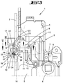
- the lock shown designed as a mortise lock according to the first embodiment has the reference number 1. Its lock case 2 is on a cuff 3 scheduled. The face plate width a is in the embodiment 16 mm.
- the lock case 2 includes one Castle floor 4 and a castle overhanging Castle ceiling 5.
- a follower 6 stored in the upper area of the lock case 2 in the upper area of the lock case 2 is a follower 6 stored in the upper area of the lock case 2 .
- the nut arm 7 engages on a projection 8 of a 9 tail. This forms in Connection with a trap head 10 a trap F.
- the trap head 10 Seen from the front of the trap is the trap head 10 approximately H-shaped. Is accordingly the trap recess 16 in the cuff 3 designed.
- the trap head 10 forms a bevel on the front 17, which in the middle of an immersion opening 18 is interrupted. The latter extends to over the trap face.
- the immersion section in question bears the reference number 19.
- the immersion opening 18 serves to receive a two-armed crank 20. This has an outer arm 21 and an inner one Arm 22, which two arms 21, 22 in one point Angles are arranged to each other. The corresponding one acute angle is greater than 60 °.
- crank 20 with its inner Arm 22 is supported in the region of the projection 31, it is possible, also a corresponding offset of the hinge pin 28 in the direction of the long side 10 '' while achieving favorable kinematic conditions. These can therefore correspond to a crank, such as it is possible with 20 mm wide gauntlets. As a support surface namely the dimension x is gained, which the protrusion of the projection 31 over the longitudinal edge corresponds to the recess 16.
- the trap head 10 forms one for the inner arm 22 adjoining the immersion opening 18, rearward Alternative room 34.
- the latter is chosen to be large that the crank 20 can be pivoted counterclockwise is.
- the trailing edge 34 'of the escape space 34 limits this pivoting movement against the force of the Leg spring 29. After swiveling lies the extreme tip of the inner arm 22 beyond the Apex of the convex projection 31 and thus allows pulling out the trap head, after previous Loosen the cross screw 13, see Fig. 6.
- the outer arm 21 forms with its from the trap slope 17 pioneering side a wall 35 of a shaft 36.
- the opposite wall 37 is from the Forend front formed.
- the Fig. 11 that the trap slopes 17 before Shaft 36 ends.
- the outer arm 21 is connected to the shaft wall section 40 adjoining arm section 41, which the latter with complete crank pivoting aligned on the outside with the slant 17, see Fig. 8. This is made possible by the immersion opening 18 of the trap head 10. A terminal angled Hook 42 then engages in the immersion section 19 of the trap face.
- the arm portion 41 forms one in the shaft 36 pointing inlet slope.
- Fig. 8 can also be seen that when complete Crank pivoting on the joint supports 25, 26, 27 existing hook projections 39 behind the faceplate lie.
- the hook projections 39 are formed by on the joint supports 25, 26, 27 throats 43. The latter is aligned with the open angle between the outer arm 21 and the inner arm 22 at occurred trap.
- Fig. 10 it is illustrated that a profiled Plastic card 46 between a door 45 or the cuff 3 and the striking plate 44 is inserted.
- the leading edge 46 'of the card thereby passes into the slot 36 and accordingly cannot be effective on the sloping slope 17 will. Unauthorized opening in this way is included Prevents security. Even with larger cracked air the plastic card 46 is directed into the slot 36, because of the infeed slope formed by the arm portion 41.
- the cuff 47 of a lock 1 ' has one design Trap recess 48, which is the cross section of a trap F 'is adjusted.
- the latter has a trap head 49 with subsequent pin 50, which is coupling in dips a trap tail 51.
- From the front edge 52 of the trap head 49 starts from a trap slope 53, which the two trap long sides 54, 55 with each other connects.
- the one opposite the trap slope 53 Trap long side 54 is therefore in the trap exclusion direction seen, longer trained than the one opposite Trap long side 55, cf. in particular Fig. 15.
- narrow sides are approximately V-shaped guide grooves 56 incorporated into which protruding form extensions 57 of the cuff 47.
- Trough-shaped on the two longitudinal sides 54, 55 of the case Constrictions 58, 59 are present, which are centered the trap head 49 in the direction of the trap movement extend.
- the course of the long sides 54, 55 are the long sides 60, 61 of the latch recess 48 customized. Accordingly, the long sides 60, 61 of Protrusions 62 and 63 protrude.
- Fig. 14 shows that the projections 62, 63 arcuate run and thus the alignment of the throat-like Constrictions 58, 59 are adapted.
- the tabs 62, 63 protrude from their long sides 60 or 61 by the dimension x '. This measure corresponds to that Amount of width y adjacent to the protrusions 62, 63 lying opening edge area 64 or 65.
Landscapes
- Engineering & Computer Science (AREA)
- Structural Engineering (AREA)
- Measurement Of The Respiration, Hearing Ability, Form, And Blood Characteristics Of Living Organisms (AREA)
- Workshop Equipment, Work Benches, Supports, Or Storage Means (AREA)
- Ladders (AREA)
- Buckles (AREA)
- Lock And Its Accessories (AREA)
Applications Claiming Priority (2)
| Application Number | Priority Date | Filing Date | Title |
|---|---|---|---|
| DE19636037A DE19636037A1 (de) | 1996-09-05 | 1996-09-05 | Schloß mit Falle |
| DE19636037 | 1996-09-05 |
Publications (3)
| Publication Number | Publication Date |
|---|---|
| EP0828047A2 true EP0828047A2 (fr) | 1998-03-11 |
| EP0828047A3 EP0828047A3 (fr) | 1998-09-23 |
| EP0828047B1 EP0828047B1 (fr) | 2003-06-25 |
Family
ID=7804705
Family Applications (1)
| Application Number | Title | Priority Date | Filing Date |
|---|---|---|---|
| EP97114580A Expired - Lifetime EP0828047B1 (fr) | 1996-09-05 | 1997-08-22 | Serrure à pêne demi-tour |
Country Status (2)
| Country | Link |
|---|---|
| EP (1) | EP0828047B1 (fr) |
| DE (2) | DE19636037A1 (fr) |
Cited By (6)
| Publication number | Priority date | Publication date | Assignee | Title |
|---|---|---|---|---|
| EP1621704A1 (fr) * | 2004-07-28 | 2006-02-01 | Carl Fuhr GmbH & Co. KG | Serrure à pêne demi-tour |
| EP2463458A3 (fr) * | 2010-12-08 | 2013-03-20 | Abloy Oy | Agencement de pêne pour un corps de verrouillage |
| WO2014096513A1 (fr) * | 2012-12-19 | 2014-06-26 | Abloy Oy | Serrure de porte |
| WO2014096512A1 (fr) * | 2012-12-19 | 2014-06-26 | Abloy Oy | Serrure de porte |
| EP3034726A1 (fr) * | 2014-12-15 | 2016-06-22 | Aug. Winkhaus GmbH & Co. KG | Contre-serrure d'une serrure a espagnolette |
| ITUB20151853A1 (it) * | 2015-07-02 | 2017-01-02 | Antonio Diez | Serratura antieffrazione |
Family Cites Families (8)
| Publication number | Priority date | Publication date | Assignee | Title |
|---|---|---|---|---|
| GB300027A (en) * | 1927-12-01 | 1928-11-08 | George Harry Burrows | Improvements in or relating to door latches and like fastenings |
| FR734800A (fr) * | 1932-04-06 | 1932-10-28 | Freyburger Sa Des Ets | Pène de serrure |
| GB513927A (en) * | 1938-04-23 | 1939-10-25 | Archibald Baird Murray Junior | Improvements in and relating to latch locks |
| DE1746397U (de) * | 1957-04-03 | 1957-06-06 | Witte & Co Ewald | Falle fuer tuerschloesser od. dgl. |
| GB1140725A (en) * | 1965-06-18 | 1969-01-22 | Josiah Parkes And Sons Ltd | Improvements in or relating to latch sets and lock sets |
| CH596418A5 (en) * | 1976-05-04 | 1978-03-15 | Glutz Ag | Noiseless lock catch with crank member |
| DE4218733A1 (de) * | 1992-06-06 | 1993-12-09 | Fuhr Carl Gmbh & Co | Falle, insbesondere an Treibstangenbeschlägen |
| DE9411156U1 (de) * | 1994-07-09 | 1994-09-22 | Barczikowski, Anton, 61231 Bad Nauheim | Fallschloß |
-
1996
- 1996-09-05 DE DE19636037A patent/DE19636037A1/de not_active Withdrawn
-
1997
- 1997-08-22 DE DE59710332T patent/DE59710332D1/de not_active Expired - Lifetime
- 1997-08-22 EP EP97114580A patent/EP0828047B1/fr not_active Expired - Lifetime
Cited By (12)
| Publication number | Priority date | Publication date | Assignee | Title |
|---|---|---|---|---|
| EP1621704A1 (fr) * | 2004-07-28 | 2006-02-01 | Carl Fuhr GmbH & Co. KG | Serrure à pêne demi-tour |
| EP2463458A3 (fr) * | 2010-12-08 | 2013-03-20 | Abloy Oy | Agencement de pêne pour un corps de verrouillage |
| WO2014096513A1 (fr) * | 2012-12-19 | 2014-06-26 | Abloy Oy | Serrure de porte |
| WO2014096512A1 (fr) * | 2012-12-19 | 2014-06-26 | Abloy Oy | Serrure de porte |
| CN104995365A (zh) * | 2012-12-19 | 2015-10-21 | 阿布莱有限公司 | 门锁 |
| US9551173B2 (en) | 2012-12-19 | 2017-01-24 | Abloy Oy | Door lock |
| AU2013366400B2 (en) * | 2012-12-19 | 2017-06-15 | Abloy Oy | Door lock |
| RU2624430C2 (ru) * | 2012-12-19 | 2017-07-03 | Аблой Ой | Дверной замок |
| AU2013366401B2 (en) * | 2012-12-19 | 2017-12-14 | Abloy Oy | Door lock |
| US10094141B2 (en) | 2012-12-19 | 2018-10-09 | Abloy Oy | Door lock |
| EP3034726A1 (fr) * | 2014-12-15 | 2016-06-22 | Aug. Winkhaus GmbH & Co. KG | Contre-serrure d'une serrure a espagnolette |
| ITUB20151853A1 (it) * | 2015-07-02 | 2017-01-02 | Antonio Diez | Serratura antieffrazione |
Also Published As
| Publication number | Publication date |
|---|---|
| EP0828047A3 (fr) | 1998-09-23 |
| EP0828047B1 (fr) | 2003-06-25 |
| DE59710332D1 (de) | 2003-07-31 |
| DE19636037A1 (de) | 1998-03-12 |
Similar Documents
| Publication | Publication Date | Title |
|---|---|---|
| EP0911470B1 (fr) | Dispositif de verrouillage | |
| EP0610542B1 (fr) | Serrure mortaisée en particulier pour portes d'appartement, notamment serrure avec barres coulissantes | |
| DE19838623C1 (de) | Türschloß für eine Ganzglastür mit feststehendem Glasseitenteil | |
| DE9104553U1 (de) | Mehrriegel-Türschloß | |
| DE19858174A1 (de) | Türschloß | |
| EP0828047B1 (fr) | Serrure à pêne demi-tour | |
| DE2813311C2 (fr) | ||
| DE69403734T2 (de) | Betätigungseinrichtung für die automatische Verriegelung eines Fensterflügels oder dergleichen | |
| DE3334298C3 (de) | Verschluß für Fenster, Türen oder dergleichen | |
| DE19902579C2 (de) | Verschlußvorrichtung für den unterschlagenden Flügel zweiflügeliger setzholzloser Fenster oder Türen | |
| DE19815671B4 (de) | Treibstangenverschluß | |
| EP0662556B1 (fr) | Dispositif de verrouillage pour porte ou fenêtre | |
| EP0928866B1 (fr) | Serrure avec pêne à demi-tour | |
| DE3606487A1 (de) | Treibstangenbeschlag | |
| EP0199270A2 (fr) | Dispositif pour maintenir une porte ou une fenêtre entrouverte dans au moins une position | |
| DE29604917U1 (de) | Kantriegelbeschlag für den Standflügel einer doppelflügeligen Tür | |
| DE3709408C2 (fr) | ||
| DE2457720A1 (de) | Rechts/links verwendbares tuerschloss | |
| DE8413327U1 (de) | Treibstangenbeschlag | |
| DE29818045U1 (de) | Beschlag für Klappfenster, insbesondere von Wohnwagen, Mobilheimen u.dgl. | |
| DE9311360U1 (de) | Verschluß- und Spaltlüftvorrichtung für ein-, zwei- oder mehrflügelige Läden von Fenstern, Türen o.dgl. | |
| DE19903373A1 (de) | Verriegelungsvorrichtung | |
| DE1923600C3 (de) | Beschlag für Fenster, Türen o.dgl., insbesondere für Dreh-Kippflügel | |
| AT341370B (de) | Schliessblech fur schlosser von turen od.dgl. | |
| DE29805362U1 (de) | Kantriegelverschluß |
Legal Events
| Date | Code | Title | Description |
|---|---|---|---|
| PUAI | Public reference made under article 153(3) epc to a published international application that has entered the european phase |
Free format text: ORIGINAL CODE: 0009012 |
|
| AK | Designated contracting states |
Kind code of ref document: A2 Designated state(s): AT BE CH DE LI |
|
| AX | Request for extension of the european patent |
Free format text: AL;LT;LV;RO;SI |
|
| PUAL | Search report despatched |
Free format text: ORIGINAL CODE: 0009013 |
|
| AK | Designated contracting states |
Kind code of ref document: A3 Designated state(s): AT BE CH DE DK ES FI FR GB GR IE IT LI LU MC NL PT SE |
|
| AX | Request for extension of the european patent |
Free format text: AL;LT;LV;RO;SI |
|
| 17P | Request for examination filed |
Effective date: 19990105 |
|
| AKX | Designation fees paid |
Free format text: AT BE CH DE LI |
|
| RBV | Designated contracting states (corrected) |
Designated state(s): AT BE CH DE LI |
|
| RBV | Designated contracting states (corrected) |
Designated state(s): DE FR GB NL |
|
| 17Q | First examination report despatched |
Effective date: 20010208 |
|
| GRAH | Despatch of communication of intention to grant a patent |
Free format text: ORIGINAL CODE: EPIDOS IGRA |
|
| GRAH | Despatch of communication of intention to grant a patent |
Free format text: ORIGINAL CODE: EPIDOS IGRA |
|
| GRAA | (expected) grant |
Free format text: ORIGINAL CODE: 0009210 |
|
| AK | Designated contracting states |
Designated state(s): DE FR GB NL |
|
| PG25 | Lapsed in a contracting state [announced via postgrant information from national office to epo] |
Ref country code: NL Free format text: LAPSE BECAUSE OF FAILURE TO SUBMIT A TRANSLATION OF THE DESCRIPTION OR TO PAY THE FEE WITHIN THE PRESCRIBED TIME-LIMIT Effective date: 20030625 Ref country code: GB Free format text: LAPSE BECAUSE OF FAILURE TO SUBMIT A TRANSLATION OF THE DESCRIPTION OR TO PAY THE FEE WITHIN THE PRESCRIBED TIME-LIMIT Effective date: 20030625 |
|
| REG | Reference to a national code |
Ref country code: GB Ref legal event code: FG4D Free format text: NOT ENGLISH |
|
| RAP2 | Party data changed (patent owner data changed or rights of a patent transferred) |
Owner name: CARL FUHR GMBH & CO. KG |
|
| REF | Corresponds to: |
Ref document number: 59710332 Country of ref document: DE Date of ref document: 20030731 Kind code of ref document: P |
|
| NLT2 | Nl: modifications (of names), taken from the european patent patent bulletin |
Owner name: CARL FUHR GMBH & CO. KG |
|
| ET | Fr: translation filed | ||
| NLV1 | Nl: lapsed or annulled due to failure to fulfill the requirements of art. 29p and 29m of the patents act | ||
| GBV | Gb: ep patent (uk) treated as always having been void in accordance with gb section 77(7)/1977 [no translation filed] |
Effective date: 20030625 |
|
| PLBE | No opposition filed within time limit |
Free format text: ORIGINAL CODE: 0009261 |
|
| STAA | Information on the status of an ep patent application or granted ep patent |
Free format text: STATUS: NO OPPOSITION FILED WITHIN TIME LIMIT |
|
| 26N | No opposition filed |
Effective date: 20040326 |
|
| PGFP | Annual fee paid to national office [announced via postgrant information from national office to epo] |
Ref country code: DE Payment date: 20120807 Year of fee payment: 16 Ref country code: FR Payment date: 20120817 Year of fee payment: 16 |
|
| PG25 | Lapsed in a contracting state [announced via postgrant information from national office to epo] |
Ref country code: DE Free format text: LAPSE BECAUSE OF NON-PAYMENT OF DUE FEES Effective date: 20140301 |
|
| REG | Reference to a national code |
Ref country code: DE Ref legal event code: R119 Ref document number: 59710332 Country of ref document: DE Effective date: 20140301 |
|
| REG | Reference to a national code |
Ref country code: FR Ref legal event code: ST Effective date: 20140430 |
|
| PG25 | Lapsed in a contracting state [announced via postgrant information from national office to epo] |
Ref country code: FR Free format text: LAPSE BECAUSE OF NON-PAYMENT OF DUE FEES Effective date: 20130902 |