EP0828093B1 - Dispositif de guidage linéaire - Google Patents
Dispositif de guidage linéaire Download PDFInfo
- Publication number
- EP0828093B1 EP0828093B1 EP97115475A EP97115475A EP0828093B1 EP 0828093 B1 EP0828093 B1 EP 0828093B1 EP 97115475 A EP97115475 A EP 97115475A EP 97115475 A EP97115475 A EP 97115475A EP 0828093 B1 EP0828093 B1 EP 0828093B1
- Authority
- EP
- European Patent Office
- Prior art keywords
- spindle
- spindle support
- runner assembly
- support units
- guide
- Prior art date
- Legal status (The legal status is an assumption and is not a legal conclusion. Google has not performed a legal analysis and makes no representation as to the accuracy of the status listed.)
- Expired - Lifetime
Links
Images

Classifications
-
- F—MECHANICAL ENGINEERING; LIGHTING; HEATING; WEAPONS; BLASTING
- F16—ENGINEERING ELEMENTS AND UNITS; GENERAL MEASURES FOR PRODUCING AND MAINTAINING EFFECTIVE FUNCTIONING OF MACHINES OR INSTALLATIONS; THERMAL INSULATION IN GENERAL
- F16H—GEARING
- F16H25/00—Gearings comprising primarily only cams, cam-followers and screw-and-nut mechanisms
- F16H25/18—Gearings comprising primarily only cams, cam-followers and screw-and-nut mechanisms for conveying or interconverting oscillating or reciprocating motions
- F16H25/20—Screw mechanisms
- F16H25/24—Elements essential to such mechanisms, e.g. screws, nuts
-
- B—PERFORMING OPERATIONS; TRANSPORTING
- B23—MACHINE TOOLS; METAL-WORKING NOT OTHERWISE PROVIDED FOR
- B23Q—DETAILS, COMPONENTS, OR ACCESSORIES FOR MACHINE TOOLS, e.g. ARRANGEMENTS FOR COPYING OR CONTROLLING; MACHINE TOOLS IN GENERAL CHARACTERISED BY THE CONSTRUCTION OF PARTICULAR DETAILS OR COMPONENTS; COMBINATIONS OR ASSOCIATIONS OF METAL-WORKING MACHINES, NOT DIRECTED TO A PARTICULAR RESULT
- B23Q5/00—Driving or feeding mechanisms; Control arrangements therefor
- B23Q5/22—Feeding members carrying tools or work
- B23Q5/34—Feeding other members supporting tools or work, e.g. saddles, tool-slides, through mechanical transmission
- B23Q5/38—Feeding other members supporting tools or work, e.g. saddles, tool-slides, through mechanical transmission feeding continuously
- B23Q5/40—Feeding other members supporting tools or work, e.g. saddles, tool-slides, through mechanical transmission feeding continuously by feed shaft, e.g. lead screw
- B23Q5/404—Screw bearings therefor
-
- F—MECHANICAL ENGINEERING; LIGHTING; HEATING; WEAPONS; BLASTING
- F16—ENGINEERING ELEMENTS AND UNITS; GENERAL MEASURES FOR PRODUCING AND MAINTAINING EFFECTIVE FUNCTIONING OF MACHINES OR INSTALLATIONS; THERMAL INSULATION IN GENERAL
- F16H—GEARING
- F16H25/00—Gearings comprising primarily only cams, cam-followers and screw-and-nut mechanisms
- F16H25/18—Gearings comprising primarily only cams, cam-followers and screw-and-nut mechanisms for conveying or interconverting oscillating or reciprocating motions
- F16H25/20—Screw mechanisms
- F16H2025/2031—Actuator casings
- F16H2025/2034—Extruded frame casings
-
- F—MECHANICAL ENGINEERING; LIGHTING; HEATING; WEAPONS; BLASTING
- F16—ENGINEERING ELEMENTS AND UNITS; GENERAL MEASURES FOR PRODUCING AND MAINTAINING EFFECTIVE FUNCTIONING OF MACHINES OR INSTALLATIONS; THERMAL INSULATION IN GENERAL
- F16H—GEARING
- F16H25/00—Gearings comprising primarily only cams, cam-followers and screw-and-nut mechanisms
- F16H25/18—Gearings comprising primarily only cams, cam-followers and screw-and-nut mechanisms for conveying or interconverting oscillating or reciprocating motions
- F16H25/20—Screw mechanisms
- F16H25/24—Elements essential to such mechanisms, e.g. screws, nuts
- F16H2025/2436—Intermediate screw supports for reducing unsupported length of screw shaft
-
- Y—GENERAL TAGGING OF NEW TECHNOLOGICAL DEVELOPMENTS; GENERAL TAGGING OF CROSS-SECTIONAL TECHNOLOGIES SPANNING OVER SEVERAL SECTIONS OF THE IPC; TECHNICAL SUBJECTS COVERED BY FORMER USPC CROSS-REFERENCE ART COLLECTIONS [XRACs] AND DIGESTS
- Y10—TECHNICAL SUBJECTS COVERED BY FORMER USPC
- Y10T—TECHNICAL SUBJECTS COVERED BY FORMER US CLASSIFICATION
- Y10T74/00—Machine element or mechanism
- Y10T74/18—Mechanical movements
- Y10T74/18568—Reciprocating or oscillating to or from alternating rotary
- Y10T74/18576—Reciprocating or oscillating to or from alternating rotary including screw and nut
- Y10T74/18648—Carriage surrounding, guided by, and primarily supported by member other than screw [e.g., linear guide, etc.]
-
- Y—GENERAL TAGGING OF NEW TECHNOLOGICAL DEVELOPMENTS; GENERAL TAGGING OF CROSS-SECTIONAL TECHNOLOGIES SPANNING OVER SEVERAL SECTIONS OF THE IPC; TECHNICAL SUBJECTS COVERED BY FORMER USPC CROSS-REFERENCE ART COLLECTIONS [XRACs] AND DIGESTS
- Y10—TECHNICAL SUBJECTS COVERED BY FORMER USPC
- Y10T—TECHNICAL SUBJECTS COVERED BY FORMER US CLASSIFICATION
- Y10T74/00—Machine element or mechanism
- Y10T74/18—Mechanical movements
- Y10T74/18568—Reciprocating or oscillating to or from alternating rotary
- Y10T74/18832—Reciprocating or oscillating to or from alternating rotary including flexible drive connector [e.g., belt, chain, strand, etc.]
- Y10T74/18848—Reciprocating or oscillating to or from alternating rotary including flexible drive connector [e.g., belt, chain, strand, etc.] with pulley
Definitions
- the invention relates to a linear guide device, comprising a guide base with a longitudinal axis, one relative to the rotor base guided in the direction of the longitudinal axis, a linear drive device for driving the Rotor assembly along the longitudinal axis, this linear drive device one relative to at least one of its ends axially fixed to the guide base, but rotatably mounted Drive spindle and one with the drive spindle in threaded engagement standing mother who is in motion for Direction of the longitudinal axis is connected to the rotor assembly and lockable against rotation with the drive spindle or is brakable, at least one relative to the rotor assembly guided in the direction of the longitudinal axis on the guide base
- Spindle support unit axially on both sides the rotor assembly, which depends on movements the rotor assembly along the longitudinal axis within each Longitudinal distance between the rotor assembly and one associated spindle end are adjustable.
- the maximum speed of movement of the rotor assembly hangs relative to the guide base in such a linear guide device from the so-called critical speed the drive spindle.
- critical speed the drive spindle is set in natural vibrations, the Amplitude a precise positioning of the rotor assembly impossible makes.
- Relevant factors affecting the critical speed determine are the diameter of the spindle and its Length. The smaller the diameter / length ratio of the drive spindle the lower the critical speed the drive spindle and accordingly the maximum Movement speed of the rotor assembly. Because in particular with long lengths of the drive spindle (e.g.
- spindle support units in the support-free Longitudinal sections of the drive spindle between the rotor assembly and arranged the spindle ends.
- the spindle support units provide additional support points for the drive spindle and shorten the length of the support-free Spindle sections.
- the critical speed of the drive spindle and the maximum movement speed of the This increases the rotor assembly. Furthermore prevent the spindle support units especially at long drive spindles Deflections of the drive spindle.
- the spindle support units are relative to the rotor assembly agile and dependent on a movement of the Rotor assembly adjustable along the longitudinal axis so that it the maximum adjustment path specified by the spindle length the rotor assembly along the longitudinal axis only about their respective Shorten overall length.
- FIGS. 8 and 9 show an embodiment known from WO 96 01198 A, for example, which forms the closest prior art to the present invention in accordance with the preamble of claim 1.
- a spindle support unit 27s, 29s is arranged there axially on both sides of a rotor assembly 9s, which are guided together with the rotor assembly 9s on a guide rail 3s.
- the rotor assembly 9s can be driven along the guide rail 3s by means of a rotatable and axially fixed drive spindle 13s, the drive spindle 13s being in engagement with a spindle nut which is axially fixed relative to the rotor assembly 9s and is non-rotatable with respect to this.
- the two spindle support units 27s, 29s are held at a fixed distance from one another by one or more rigid connecting rods 101s.
- the rotor assembly 9s is freely movable within the longitudinal distance between the two spindle support units 27s, 29s. As soon as the rotor assembly 9s strikes one of the spindle support units 27s, 29s, it moves the two spindle support units 27s, 29s in the same direction as it moves along the guide rail 3s, namely pushing the spindle support unit in front of it in direct contact with it, while dragging the spindle support unit behind her in the direction of movement at a distance behind her.
- the two spindle support units 27s, 29s are abruptly braked by a stop of the spindle support unit in the direction of movement at a suitable counter-stop fixed to the guide rail, the spindle support unit in the direction of movement pushing back due to inertia.
- the thrust forces applied to the connecting rods 101s can be considerable, especially in the case of a vertical arrangement, especially when one considers that travel speeds of the rotor assembly 9s in the order of magnitude of 1 m / s or more are not uncommon and also with heavy loads to be moved by the linear guide device the spindle support units 27s, 29s can be built correspondingly solid.
- the connecting rods 101s In order not to buckle under such a thrust load, the connecting rods 101s must be very stiff against shear and have a correspondingly large cross section, which can lead to space problems in a confined operating environment of the linear guide device. It should be taken into account that even if the rotor assembly is braked specifically before reaching a final position, this targeted braking of the leading spindle support unit is not communicated, which is why this leading spindle support unit can hit a stop with the motion impulse communicated to it by the rotor assembly before braking. In addition, the comparatively high weight of the connecting rods 101s is disadvantageous, since on the one hand the linear guide device becomes heavier overall, and on the other hand the connecting rods 101s represent masses to be moved.
- a linear guide device is known from EP 0 412 072 B1 known with a spindle drive, in the axially on both sides of one one rotor assembly to be moved by the spindle drive additional support nut is provided to support the spindle s is.
- the two support nuts are neither moving together coupled, they are still with the rotor assembly in drive connection. They are each as with the spindle threaded nut running, which itself when rotating the spindle with about half the speed of movement the rotor assembly moves along the spindle.
- the thread pitch of the spindle, the radial clearance or the radial preload of the balls between the Raceways of the outer part and the thread of the spindle as well the radial play or the radial preload in the bearings between the ball cage and the outer part are suitable for each other be coordinated. This is with a considerable manufacturing effort connected.
- the invention is based on the technical problem of a Linear guide device of the type described in the introduction with simple means and small space requirements of these means the spindle support units always along the drive spindle to be able to position that deflections and Natural vibrations of the drive spindle are effectively avoided.
- a linear guide device is used to solve this problem proposed according to claim 1.
- a flexible traction means is provided as a pair coupling means acts. It is suitable for any application, for example to carry a tool or a workpiece in a processing machine or for guidance of a measuring carrier in a measuring device.
- At least A flexible traction device can be made from a monofilament wire Plastic or metal, a rope, in particular a wire rope, a band or a strap. Its advantages are light in weight and small. Space requirements.
- the spindle support units at least of a pair arranged on both sides of the rotor assembly Spindle support units by at least one if desired, including loop closures flexible pair coupling means closed in a loop their movements are mutually coordinated, which one attacks on the spindle support units and in the area the spindle ends are deflected by deflecting means.
- Paired coupling means used flexible traction the same function as the rigid Connecting rods in the known embodiment, namely the two arranged on both sides of the rotor assembly Spindle support units at a fixed distance from each other to hold and so coordinate their movements.
- the adjustment of the spindle support units when moving the rotor assembly is achieved in that the spindle support units one by one flexible Coupling means of mutually motion-matched pairs of spindle support units through a stop connection between the rotor assembly and one of the two Spindle support units are adjustable. At this The rotor assembly picks up the solution during a movement Direction towards a spindle end the pair of spindle support units in the same direction and at the same speed With.
- the rotor assembly Since the rotor assembly is in the direction of movement spindle support unit located behind it dragged at an axial distance is in the process of approximation the rotor assembly is always guaranteed at one end of the spindle, that then in the spindle section of the drive spindle between the rotor assembly and the other end of the spindle at least a sufficient distance from the rotor assembly an additional support point for the drive spindle located.
- spindle support units are multiple pairs from either side of the rotor assembly arranged spindle support units available, so this principle of adjustment of the spindle support units can extended by a stop connection be that the spindle support units at least a pair of spindle support units further from the rotor, the opposite side by a flexible pair coupling means are motion-matched by a stop connection between a spindle support unit closer to the rotor and one of the two runners further away Spindle support units are adjustable.
- a spindle support unit one made of a low-friction material, in particular Plastic, manufactured spindle body with a Has through hole, which is slidable from the spindle is enforced.
- This can e.g. be a sliding sleeve.
- a spindle support unit one in threaded engagement with the drive spindle Support nut.
- You can then get a commercial one Use the mother as a support nut, for example also used to drive the rotor assembly comes.
- a such support nut can provide perfect guidance of the drive spindle ensure in the spindle support unit.
- This possibility of compensation may consist in that Support nut in the spindle support unit axially immobile, but is rotatably mounted so that one predetermined dependency between the movement of the rotor assembly and the movement of the respective spindle support unit corresponding speed difference this allows both longitudinal movements by rotating the support nut is. Doing so will increase the slope of the drive spindle and the support nut formed screw drive friction conditions determined by radial play or radial preload between support nut and drive spindle as well the friction within the between the support nut and the spindle support unit arranged bearings suitably coordinate with each other to the respective case constellation (e.g. standstill of the spindle support unit at Longitudinal movement of the rotor assembly) can be realized.
- a support nut in a spindle support unit also has the advantage of high wear resistance. If a sliding sleeve is used to support the drive spindle, wear of the sliding sleeve can occur, particularly in the case of rolled spindles, that is to say spindles with a thread groove produced by a roller tool, due to material build-up which can occur when the spindle rolls between individual turns. This abrasion is lower with ground spindles. Nevertheless, by using a support nut, in particular a ball nut, the wear in the spindle support unit can be significantly reduced.
- a spindle support unit which comprises a ball screw drive with at least one endless row of balls, which follows a thread path on the inner circumferential surface of the support nut over part of its length and runs on a remaining path through a return channel of the support nut.
- the guide base can have at least one guide surface on which both the rotor assembly and the spindle support units are guided. Alternatively, at least one separate guide surface can be provided on the guide base for guiding the spindle support units and the rotor assembly.
- a secondary guide rail is guided on the guide base, on which two spindle support units are immovably arranged, and that the rotor assembly is movably guided in the direction of the longitudinal axis on this secondary guide rail relative to the two spindle support units is.
- the invention is not limited to any particular design Management base limited.
- the leadership base can e.g. of be formed a solid carrier bed on which one or several guide rails are attached.
- the guide base Guide housing with walls delimiting a guide cavity includes and the rotor assembly and the spindle support units are received in the guide cavity, wherein the rotor assembly has a longitudinal opening in the guide housing interspersed and outside the guide cavity for receiving an object to be moved in the direction of the longitudinal axis is trained. This can then be done within the guide cavity at least one guide rail for guiding the Rotor assembly or / and the spindle support units be attached to the guide housing.
- the rotor assembly and the spindle support units are preferred by Rolling elements guided on the guide base, for example by Balls, barrel-shaped rollers or disc-shaped rollers.
- the rotor assembly and / or the spindle support units at least one endless rolling element loop have for their leadership on the leadership base. It is also a slide bearing of the rotor assembly and the Spindle support units conceivable.
- the at least one flexible traction device expediently runs at least in part within the guide cavity. This lends itself because the at least one flexible traction device in this way from damage and pollution is protected. It is particularly advantageous if that at least one flexible traction device on at least one part its length in a traction means receiving groove open towards the guide cavity is recorded, which in one of the Guide cavity bounding walls is formed. On the one hand the at least one flexible traction device is in the traction device receiving groove perfectly protected, on the other hand it can even in confined spaces within the guide cavity the at least one flexible traction means at least are partially guided within the guide cavity. If the guide housing is a profile housing with one or more longitudinal fastening grooves, can advantageously one of these fastening grooves without additional design effort serve as a traction device receiving groove.
- a flexible traction device can consist of at least along part of its length in one of the guide cavity separate traction device receiving channel runs.
- This solution offers especially because the at least one flexible Traction means designed as flexible pair coupling means is. You can thus have a returning run of this flexible Guide pair coupling means in the traction device receiving channel and in the area of the associated deflection means from the traction means receiving channel let out.
- the guiding cavity is to protect against the ingress of dirt in the area of its longitudinal opening preferably by a Masking tape covered, which either with the rotor assembly is in drive connection or through the rotor assembly is passed through.
- the deflecting means can then first of all be attached without the associated encapsulant so that then the at least one flexible traction device or / and the masking tape without obstruction by the encapsulant can be put on easily. The attachment of the encapsulant takes place only afterwards.
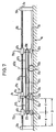
- a guide base 1 is shown on which a guide rail 3 is fixed with a longitudinal axis 5.
- the guide rail 3 has at least one guide surface 7 the one rotor assembly 9 can be displaced along the longitudinal axis 5 is led.
- the drive of the rotor assembly 9 along the Longitudinal axis 5 takes place by means of a spindle drive device 11, which has a drive spindle 13 with a longitudinal axis 5 parallel spindle axis and one with the drive spindle 13 threaded nut 15 includes.
- the drive spindle 13 is rotatably supported at its ends, namely on its right end in Fig.
- FIG. 1 in a schematically indicated Fixed bearing 17, which axially fixes the drive spindle 13 holds, and at its left end in Fig. 1 also in one only schematically indicated floating bearing 19, which axial compensatory movements the drive spindle 13 for example thermal expansion allowed.
- the drive spindle 13 can not by one shown drive motor, for example an electric motor, be rotated.
- the nut 15 is axially immovable and non-rotatably connected to the rotor assembly 9, so that when the drive spindle 13 rotates, the rotor assembly 9 at a speed along the longitudinal axis 5 is moved, which is the product of the speed of the drive spindle 13 and the slope of the between the drive spindle 13 and the nut 15 formed thread corresponds.
- the rotor assembly 9 comprises a roller 3 on the guide rail slide-mounted rotor 21, which with a mother 15 receiving connector 23 is connected. On the connector 23 is attached to a table 25 on which one to be moved Object, for example a tool or a workpiece, can be saddled.
- the rotor assembly 9 must but not in this way as a carrier of loads to be moved be executed. Instead of the table 25, a driver can also be used be provided in engagement with one to be moved Object stands without taking on a load carrying function.
- the one formed by the drive spindle 13 and the nut 15 Spindle drive is preferably a rolling element screw drive, in particular ball screw drive, with at least one. roller system trained with an endless array of Rolling elements is occupied.
- the outer peripheral surface of the drive spindle 13 can at least one helically around the Have spindle axis extending thread groove into which the Engage the rolling elements of the rolling element circulation.
- a drive spindle smooth on its outer circumferential surface 13 to use in which the load-transmitting rolling elements between the nut 15 and the drive spindle 13 such are radially biased that an axial locomotion the nut 15 due to the frictional engagement between these rolling elements and the smooth outer peripheral surface of the drive spindle 13 is made possible.
- a spindle support unit 27 1 and 29 1 is provided on both sides of the rotor assembly 9, which form additional support points for the drive spindle 13 in the free spindle sections between the rotor assembly 9 and the respective spindle end.
- the spindle support units 27 1 and 29 1 are movable relative to the rotor assembly 9 along the longitudinal axis 5, wherein they are guided on the guide surface 7 of the guide rail 3.
- the two spindle support units 27 1 and 29 1 are coupled to one another by a flexible pair coupling means 31 designed as a pull rope.
- a first traction cable section 31 'running between the two spindle support units 27 1 and 29 1 is movably guided past the rotor assembly 9 and fastened to the spindle support units 27 1 , 29 1 at fixed points 33.
- Another, second pull cable section 31 ′′ is fastened at fixed points 35 on the two spindle support units 27 1 , 29 1 and deflected at both ends of the guide base 1 by deflection rollers 37.
- the second traction cable section 31 ′′ forms between the two deflection rollers 37 a returning strand of the traction cable 31 closed to an endless loop, the upper strand of which is formed by the first traction cable section 31 ′.
- the two spindle support units 27 1 and 29 1 are held at a fixed distance from one another by the traction cable 31 and experience a synchronous movement as soon as one of the spindle support units 27 1 , 29 1 is set in motion.
- the spindle support unit 27 1 and thus also the spindle support unit 29 1 remain at a standstill until the rotor assembly 9 strikes the spindle support unit 27 1 .
- the two spindle support units 27 1 , 29 1 are then taken along in the same direction of movement, the rotor assembly 9 pushing the spindle support unit 27 1 in front of it in direct contact with it, while the spindle support unit 29 1 behind it is at a maximum distance follows.
- the spindle support unit 27 1 comes to rest on a stop or buffer of this left end of the guide base 1, which is not shown in detail, the second pull cable section 31 ′′ exerting a restraining tensile force on the spindle support unit 29 1 that brakes this spindle support unit.
- the rotor assembly 9 moves in the opposite direction along the longitudinal axis 5, ie to the right in FIG. 1, the situation is reversed accordingly.
- the drive spindle 13 is always supported in a central region by the spindle support unit 27 1 or 27 1 located behind the rotor assembly 9 in the direction of movement (although not exactly in the middle between the rotor assembly 9 and the respective end of the Guide base 1), so that the risk of deflection of the drive spindle 13 is effectively avoided and there are no excessively long support-free spindle sections when the rotor assembly 9 is already near one end of the guide base 1.
- the fixed bearing 17 and the floating bearing 19 for the drive spindle 13 can together with the deflection rollers 37 and, if necessary, clamping means summarized for tensioning the pull rope 31 in end cross members 39 be what as building blocks at the ends of the guide base 1 can be attached.
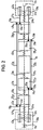
- FIG. 2 is a schematic illustration of a linear guide device with an imaginary view from above ago. For the sake of clarity, the basis of management is not shown in this schematic. However, it is of course, that here too at least one of the guide rails 3 of Fig. 1 comparable guide element for Guiding the rotor assembly and the spindle support units is provided.
- FIG. 2 differs from that of FIG. 1 essentially in that, in addition to the spindle support units 27 1 a and 29 1 a, a further, second pair of spindle support units 27 2 a and 29 2 a arranged on both sides of the rotor assembly 9 a Support of the drive spindle 13a is provided.
- the spindle support unit 27 2 a is arranged between the spindle support unit 27 1 a and the left end of the guide base in FIG. 2, while the spindle support unit 29 2 a is arranged between the spindle support unit 29 1 a and the right end of the guide base in FIG.
- the spindle support units 27 1 a and 29 1 a form a closer pair of spindle support units and the spindle support units 27 2 a and 29 2 a form a remote pair of spindle support units.
- a further pull rope 41a is provided in order to couple the two spindle support units 27 2 a and 29 2 a to one another.
- a first pull cable section 41'a, movable past the rotor assembly 9a and the spindle support units 27 1 a, 29 1 a, runs between the two spindle support units 27 2 a and 29 2 a and engages at fixed points 43 a on the spindle support units 27 2 a, 29 2 a an.
- a second traction rope is 41''a to fixed points 45a on the spindle support units 27 2 a, 29 2 a mounted and guided on a further set of guide rollers 47a, which are arranged together with the guide rollers 37a at the ends of the guide base. Due to the selected viewing direction, the returning strand of both traction cables 31a and 41a cannot be seen.
- the traction cable 41a also serves as a flexible pair coupling means for the spindle support units 27 2 a, 29 2 a and connects these two spindle support units 27 2 a, 29 2 a for common, synchronous movement.
- the rotor assembly 9a moves in FIG. 2 to the left, the rotor assembly 9a initially abuts the spindle support unit 27 1 a and, as a result, takes the pair of spindle support units 27 1 a, 29 1 a closer to the rotor with the same speed.
- the two spindle support units 27 2 a and 29 2 a are initially at a standstill.
- the spindle support unit 27 1 a pushed in front of the rotor assembly 9 a reaches the spindle support unit 27 2 a and strikes it.
- the pair of spindle support units 27 2 a, 29 2 a further away from the rotor is also set in motion, namely at the same speed as the rotor assembly 9 a.
- the spindle support units 29 1 a and 29 2 a are then at a maximum distance from the rotor assembly 9a and from one another, so that an optimal support of the drive spindle 13a is always provided in the direction of movement behind the rotor assembly 9a.
- the reverse conditions apply accordingly.
- buffer elements 49 a can be attached to dampen the impact with one another or with the rotor assembly 9 a.
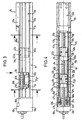
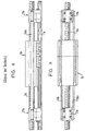
- Figures 3 to 6 show a concrete implementation example of the linear guide device shown only schematically in Fig. 2.
- the guide base 1b is formed by a profile guide housing 51b with a bottom wall 53b and two side walls 55b which are approximately perpendicular to the bottom wall 53b and parallel to one another.
- the bottom wall 53b and the side walls 55b delimit between them a guide cavity 57b in which the rotor assembly 9b and the spindle support units are accommodated.
- FIGS. 3 and 4 only show one half of the linear guide device, only the spindle support units 27 1 b and 27 2 b can be seen, with spindle support units 29 1 a and 29 2 a of FIG.
- the guide housing 51b has a longitudinal opening 59b (see FIG. 4) through which the connection part 23b of the rotor assembly 9b is made to the table 25b.
- the guide rail 3b is inserted into a bottom groove 61b in the side of the bottom wall 53b facing the guide cavity 57b and fastened there by means of fastening screws 63b.
- the spindle support units 27 1 b and 27 2 b each have a guide element 65b which guides the spindle support units on the guide rail 3b.
- the guide elements 65b and the rotor 21b of the rotor assembly 9b can be identical components, whereby standard series elements can be used.
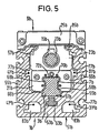
- FIGS. 5 and 6 show that the rotor 21b of the rotor assembly 9b and the guide elements 65b of the spindle support units surround the guide rail 3b in a U-shaped manner, with two leg parts 66b arranged on both sides of the guide rail 3b being adjacent to side surfaces 68b of the guide rail 3b and with one the web parts 70b connecting the leg parts 66b lie adjacent to a head surface 72b of the guide rail 3b remote from the bottom wall 53b.
- Endless rolling element loops can be integrated in the leg parts 66b of the rotor 21b and the guide elements 65b, the load-transmitting rolling element sections of which are in rolling engagement with the guide surfaces 7b provided on the side surfaces 68b of the guide rail 3b.
- the spindle support units To support the drive spindle 13b, the spindle support units have a support element 67b which is fastened to the respective guide element 65b and through which the drive spindle 13b passes.
- the support element 67b is designed as a sliding sleeve, preferably made of plastic, with a through bore 69b, the diameter of which is slightly larger than the diameter of the drive spindle 13b and in which the drive spindle 13b is slidably guided.
- the spindle support units have a clamping piece 71b which is attached to an end face of the respective spindle support unit and which provides the fixed points 33b, 35b or 43b, 45b for fastening the pull cables 31b and 41b.
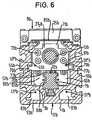
- the clamping piece 71b can be fastened to the support element 67b or to the guide element 65b of the respective spindle support unit by means of fastening screws 73b (see FIG. 6). Further fastening screws 75b (see FIG. 4) serve to fasten the support element 67b to the guide element 65b of the respective spindle support unit.
- the guide housing 51b a plurality of undercut T-profile grooves 77b both on its outside and on the guide cavity 57b facing inside. These profile grooves 77b can attach to the guide housing 51b a superordinate construction or for fastening Attachments can be used on the guide housing 51b.
- the second traction rope 31''b of the traction cable 31b b is fixed to the fixed point 35b on the clamping piece 71b of the spindle support unit 27 1 and by a passage hole 81b (see Figure 6) 27 2 passed b movable in the clamping piece 71b of the spindle support unit.
- the returning run of the pull cable 31b formed by the pull cable section 31 ′′ b is guided in a hollow chamber 83b, which is formed separately from the guide cavity 57b in the bottom wall 53b of the guide housing 51b.
- the second pull cable section 41 ′′ b of the pull cable 41 b is fastened to the fixed point 45 b of the clamping piece 71 b of the spindle support unit 27 2 b, the returning run of the pull cable 41 b formed by this second pull cable section 41 ′′ b also likewise being guided in a hollow chamber 83 b of the guide housing 51 b is.
- the projection 79b on the left in the illustration belongs to the clamping piece 71b of the spindle support unit 27 2 b, while the projection 79b indicated on the right side of this clamping piece 71b belongs to the clamping piece 71b of the spindle support unit 27 1 b closer to the runner heard.
- the pull cable sections 31'b and 41'b and the associated fixed points 33b and 43b cannot be seen in this FIG. 6, since they are covered by the projections 79b in the viewing direction of FIG. 6.
- the guide cavity 57b is in the region of the longitudinal opening 59b covered by a masking tape 85b to prevent the ingress of To prevent dirt in the guide cavity 57b.
- the masking tape can be made of metal or plastic and either via suitable redirections by the rotor assembly 9b can be passed through or with the rotor assembly 9b in Drive connection stand and by deflecting the Ends of the guide housing 51b be deflected.
- Fig. 4 it can be seen that the deflection rollers 37b and 47b Deflection roller carriers 87b are mounted. This pulley carrier 87b are connected to mounting flanges 88b, which releasably attached to the ends of the guide housing 51b are.
- the deflection rollers 37b, 47b and the deflection roller carrier 87b are encapsulated by encapsulation elements 89b.
- the encapsulation elements 89b are mediated by the mounting flanges 88b at the ends of the guide housing 51b and are either on the mounting flanges 88b and / or on attached to the guide housing 51b so that the guide rollers 37b, 47b with the deflecting roller carriers 37b initially separately can be attached to the guide housing 51b and after the encapsulation elements 89b can be attached.
- the encapsulation elements 89b can in turn be in one piece with the respective Traverse 39b be formed. This is a simplification guaranteed when assembling the linear guide device, because the pull cables 31b, 41b easily over the still encapsulated deflection rollers 37b, 47b and with the Spindle support units can be connected.
- the tensioning cables 31b, 41b can thereby be tensioned, for example take place that the deflection rollers 37b, 47b relative to the deflection roller carriers 87b or this deflection roller carrier 87b opposite the guide housing 51b are adjustable.
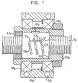
- the support nut 135g has at least a schematically indicated endless row of balls 137g on which is of a helical shape around the spindle axis extending section 139g, two to this section 139g subsequent arc sections 141g and one of the two Return sections 143g connecting arc sections 141g are formed is.
- the balls of section 139g are in one not shown helical thread groove in the inner circumferential surface of the support nut 135g. At the same time, they are aligned with the outer circumferential surface of the drive spindle 13g engaged, which - as before mentioned - can be threaded or smooth.
- the arc sections 141g and the return section 143g of the Row of balls 137g are in a return channel, not shown the support nut 135g.
- the support nut 135g can be a conventional series part, as it is for ordinary ones Ball screw drive is used. It is in one Sleeve 145g inserted and in this by means of a locking ring 147g and a stop shoulder 149g on the inner circumferential surface the sleeve 145g axially immovable. By a radially protruding nose 151g, which in an associated Recess in the inner peripheral surface of the sleeve 145g engages, the support nut 135g is non-rotatable with the sleeve 145g connected.
- the sleeve 145g is itself a spherical or roller bearing device 153g, in particular a radial or angular contact ball bearing device, in an outer ring 155g added.
- This 155g outer ring is non-rotatable Connection with the guide element (not shown in FIG. 8) 65b of a spindle support unit of the linear guide device according to Figures 3 to 6 or with a provided housing not shown, which ultimately on the guide base of the linear guide device is guided longitudinally.
Landscapes
- Engineering & Computer Science (AREA)
- Mechanical Engineering (AREA)
- General Engineering & Computer Science (AREA)
- Transmission Devices (AREA)
- Bearings For Parts Moving Linearly (AREA)
- Guides For Winding Or Rewinding, Or Guides For Filamentary Materials (AREA)
- Forwarding And Storing Of Filamentary Material (AREA)
Claims (18)
- Dispositif de guidage linéaire, comprenant :les unités de soutien de broche (271, 291) d'au moins une paire d'unités de soutien de broche (271, 291) disposées des deux côtés de l'ensemble curseur (9) ayant des mouvements mutuellement coordonnés par au moins un moyen de couplage de paire qui se met en prise sur les unités de soutien de broche (271, 291), et les unités de soutien de broche (271, 291) d'une paire d'unités de soutien de broche (271, 291) aux mouvements mutuellement coordonnés par le moyen de couplage de paire pouvant être déplacées par une liaison à butée entre l'ensemble curseur (9) et à chaque fois l'une des deux unités de soutien de broche (271, 291),une base de guidage (1) avec un axe longitudinal (5),un ensemble curseur (9) guidé par rapport à la base de guidage (1) dans la direction de l'axe longitudinal (5),un dispositif d'entraínement linéaire (11) pour entraíner l'ensemble curseur (9) le long de l'axe longitudinal (5), ce dispositif d'entraínement linéaire comprenant une broche d'entraínement (13) montée à au moins une de ses extrémités de manière fixe axialement, mais rotative par rapport à la base de guidage (1), ainsi qu'un écrou (15) en prise filetée avec la broche d'entraínement (13), qui est relié à l'ensemble curseur (9) pour un mouvement dans la direction de l'axe longitudinal (5) et peut être bloqué ou freiné contre une rotation avec la broche d'entraínement,à chaque fois au moins une unité de soutien de broche (271, 291) guidée sur la base de guidage (1) de manière mobile par rapport à l'ensemble curseur (9) dans la direction de l'axe longitudinal (5), axialement de chaque côté de l'ensemble curseur (9), unités qui sont mobiles en fonction de mouvements de l'ensemble curseur (9) le long de l'axe longitudinal (5) à l'intérieur de la distance longitudinale respective séparant l'ensemble curseur (9) d'une extrémité de broche associée,
caractérisé en ce qu'il est prévu comme moyen de couplage de paire au moins un moyen de traction (31) flexible fermé en boucle, qui est renvoyé par des moyens de renvoi (37) au niveau des extrémités de la broche. - Dispositif de guidage linéaire selon la revendication 1, caractérisé en ce qu'au moins deux unités de soutien de broche (271a, 272a, 291a, 292a) sont prévues à chaque fois des deux côtés de l'ensemble curseur (9a), deux unités de soutien de broche (271a, 291a) plus proches de l'ensemble curseur (9a) formant des deux côtés de l'ensemble curseur (9a) une paire plus proche du curseur et deux unités de soutien de broche (272a, 292a) plus éloignées de l'ensemble curseur (9a) formant des deux côtés de l'ensemble curseur (9a) une paire plus éloignée du curseur, et les unités de soutien de broche d'au moins de l'une de ces paires (271a-291a, 272a-292a) présentant des mouvements mutuellement coordonnés.
- Dispositif de guidage linéaire selon la revendication 2, caractérisé en ce qu'un moyen de couplage de paire (31a, 41a) flexible est prévu pour chacune des paires d'unités de soutien de broche (271a-291a, 272a-292a) placées des deux côtés de l'ensemble curseur (9a).
- Dispositif de guidage linéaire selon la revendication 2 ou 3, caractérisé en ce que les unités de soutien de broche d'au moins une paire d'unités de soutien de broche (272a, 292a) plus éloignées du curseur, dont les mouvements sont coordonnés par un moyen de couplage de paire (41a) flexible, peuvent être déplacés par une liaison à butée entre une unité de soutien de broche (271a, 291a) plus proche du curseur et à chaque fois l'une des deux unités de soutien de broche (272a, 292a) plus éloignées du curseur.
- Dispositif de guidage linéaire selon l'une des revendications 1 à 4, caractérisé en ce qu'une unité de soutien de broche (271b, 272b) présente un corps de monture de broche (67b) fabriqué dans un matériau propice au glissement, en particulier une matière plastique, avec un perçage traversant (69b), qui est traversé par la broche (13b) de manière mobile par glissement.
- Dispositif de guidage linéaire selon l'une des revendications 1 à 5, caractérisé en ce qu'une unité de soutien de broche comprend un écrou de soutien (135g) en prise filetée avec la broche d'entraínement (13g), écrou qui est monté immobile axialement, mais de façon rotative dans l'unité de soutien de broche, de telle sorte qu'une différence de vitesse, correspondant à une dépendance prédéfinie entre le mouvement de l'ensemble curseur et le mouvement de l'unité de soutien de broche concernée, entre ces deux mouvements longitudinaux est rendue possible par rotation de l'écrou de soutien (135g).
- Dispositif de guidage linéaire selon l'une des revendications 1 à 6, caractérisé en ce que la base de guidage (1) présente au moins une surface de guidage (7) sur laquelle sont guidés aussi bien l'ensemble curseur (9) que les unités de soutien de broche (271, 291).
- Dispositif de guidage linéaire selon l'une des revendications 1 à 6, caractérisé en ce que, pour le guidage des unités de soutien de broche et de l'ensemble curseur, au moins une surface de guidage séparée est prévue à chaque fois sur la base de guidage.
- Dispositif de guidage linéaire selon l'une des revendications 1 à 8, caractérisé en ce que la base de guidage (1b) comprend un boítier de guidage (51b) avec des parois (53b, 55b) délimitant une cavité de guidage (57b) et l'ensemble curseur (9b) et les unités de soutien de broche (271b, 272b) sont logées dans la cavité de guidage (57b), l'ensemble curseur (9b) traversant une ouverture longitudinale (59b) du boítier de guidage (51b) et étant formé à l'extérieur de la cavité de guidage (57b) pour recevoir un objet à déplacer dans la direction de l'axe longitudinal.
- Dispositif de guidage linéaire selon la revendication 9, caractérisé en ce qu'à l'intérieur de la cavité de guidage (57b), au moins un rail de guidage (3b) pour le guidage de l'ensemble curseur (9b) et/ou des unités de soutien de broche (271b, 272b) est fixé sur le boítier de guidage (51 b).
- Dispositif de guidage linéaire selon la revendication 9 ou 10, caractérisé en ce que le moyen de traction (31b, 41b) flexible au nombre d'au moins un s'étend au moins en partie à l'intérieur de la cavité de guidage (57b).
- Dispositif de guidage linéaire selon la revendication 11, caractérisé en ce que le moyen de traction (31b, 41b) flexible au nombre d'au moins un est logé sur au moins une partie de sa longueur dans une rainure (77b) de réception de moyen de traction ouverte en direction de la cavité de guidage (57b), qui est réalisée dans l'une des parois (53b, 55b) délimitant la cavité de guidage (57b).
- Dispositif de guidage linéaire selon la revendication 12, caractérisé en ce que le moyen de traction (31b, 41b) logé dans la rainure (77b) de réception de moyen de traction ou sa partie concernée passe en mouvement devant ou est fixé à une zone de contour de l'ensemble curseur (9b) voisine de cette rainure (77b) de réception de moyen de traction, et/ou passe devant ou est fixé à au moins une unité de soutien de broche (271b, 272b).
- Dispositif de guidage linéaire selon la revendication 13, caractérisé en ce que le moyen de traction (31b, 41b) logé dans la rainure (77b) de réception de moyen de traction ou sa partie concernée est fixé à une saillie de l'ensemble curseur (9b) et/ou à une saillie (79b) d'au moins l'une des unités de soutien de broche (271b, 272b) qui dépasse à l'intérieur de la rainure (77b) de réception de moyen de traction.
- Dispositif de guidage linéaire selon l'une des revendications 9 à 14, caractérisé en ce que le moyen de traction flexible (31b, 41b) au nombre d'au moins un s'étend sur au moins une partie de sa longueur dans un canal (83b) de réception de moyen de traction séparé de la cavité de guidage (57b).
- Dispositif de guidage linéaire selon l'une des revendications 9 à 15, caractérisé en ce que la cavité de guidage (57b) est recouverte au niveau de son ouverture longitudinale (59b) par une bande de couverture (85b) qui est en liaison d'entraínement avec l'ensemble curseur (9b) ou passe à travers l'ensemble curseur (9b).
- Dispositif de guidage linéaire selon l'une des revendications 9 à 16, caractérisé en ce que le moyen de traction flexible (31b, 41b) au nombre d'au moins un et/ou une bande de couverture (85b) en liaison d'entraínement avec l'ensemble curseur (9b) s'étend dans au moins une partie d'extrémité du boítier de guidage (51b) sur des moyens de renvoi (37b, 47b) encapsulés par des moyens d'encapsulation (89b), ces moyens de renvoi (89b) pouvant être introduits dans la zone d'extrémité concernée du boítier de guidage (51b) séparément des moyens d'encapsulation (89b), et les moyens d'encapsulation (89b) associés pouvant être fixés au boítier de guidage (51b) et/ou à un rail de guidage (3b) de ce boítier de guidage (51b) et/ou aux moyens de renvoi (37b, 47b) en position d'encapsulation par rapport aux moyens de renvoi (37b, 47b) après la mise en place des moyens de renvoi (37b, 47b).
- Dispositif de guidage linéaire selon la revendication 6, caractérisé en ce que l'unité de soutien de broche comprend un entraínement à vis à billes avec au moins une rangée de billes sans fin (137g) qui, sur une partie de sa longueur, suit une voie filetée sur la surface de circonférence intérieure de l'écrou de soutien (135g) et passe sur une course résiduelle à travers un canal de retour de l'écrou de soutien (135g).
Priority Applications (1)
| Application Number | Priority Date | Filing Date | Title |
|---|---|---|---|
| DE29724669U DE29724669U1 (de) | 1996-09-06 | 1997-09-05 | Linearführungseinrichtung |
Applications Claiming Priority (2)
| Application Number | Priority Date | Filing Date | Title |
|---|---|---|---|
| DE19636272 | 1996-09-06 | ||
| DE19636272A DE19636272A1 (de) | 1996-09-06 | 1996-09-06 | Linearführungseinrichtung |
Publications (3)
| Publication Number | Publication Date |
|---|---|
| EP0828093A2 EP0828093A2 (fr) | 1998-03-11 |
| EP0828093A3 EP0828093A3 (fr) | 1998-07-01 |
| EP0828093B1 true EP0828093B1 (fr) | 2003-10-29 |
Family
ID=7804864
Family Applications (1)
| Application Number | Title | Priority Date | Filing Date |
|---|---|---|---|
| EP97115475A Expired - Lifetime EP0828093B1 (fr) | 1996-09-06 | 1997-09-05 | Dispositif de guidage linéaire |
Country Status (4)
| Country | Link |
|---|---|
| US (1) | US5974904A (fr) |
| EP (1) | EP0828093B1 (fr) |
| JP (1) | JP2952221B2 (fr) |
| DE (2) | DE19636272A1 (fr) |
Families Citing this family (31)
| Publication number | Priority date | Publication date | Assignee | Title |
|---|---|---|---|---|
| US6000308A (en) * | 1998-03-23 | 1999-12-14 | Flow International Corporation | Screw drive method and apparatus |
| DE20002865U1 (de) | 1999-04-26 | 2000-05-18 | Rexroth Star GmbH, 97424 Schweinfurt | Lineareinheit |
| WO2001039923A2 (fr) * | 1999-11-30 | 2001-06-07 | HüLLER HILLE GMBH | Machine-outil, notamment machine-outil a plateau long |
| DE10002849C2 (de) * | 2000-01-24 | 2002-03-28 | Rexroth Star Gmbh | Lineareinheit |
| DE10202737B9 (de) * | 2002-01-24 | 2015-08-06 | Robert Bosch Gmbh | Linearführungseinheit |
| DE10215832A1 (de) * | 2002-04-10 | 2003-10-30 | Neff Antriebstech Automation | Linearantriebseinrichtung |
| DE102004007126A1 (de) * | 2004-02-12 | 2005-08-25 | Stabilus Gmbh | Vorrichtung zum motorischen Öffnen und Schließen eines Karosserieteils |
| AU2005306159A1 (en) * | 2004-11-17 | 2006-05-26 | Linak A/S | A linear actuator |
| CN101837554A (zh) * | 2010-05-19 | 2010-09-22 | 杭州机床集团有限公司 | 机床长丝杠牵引式随动支承装置 |
| WO2012046387A1 (fr) * | 2010-10-08 | 2012-04-12 | 平田機工株式会社 | Dispositif de curseur |
| DE102011003698B4 (de) | 2011-02-07 | 2019-05-09 | Schaeffler Technologies AG & Co. KG | Spindelantrieb |
| CN102699739A (zh) * | 2012-06-19 | 2012-10-03 | 无锡华联精工机械有限公司 | 回转式机床的动力头纵向移位机构 |
| DE202012102316U1 (de) * | 2012-06-22 | 2013-09-25 | Rk Rose + Krieger Gmbh Verbindungs- Und Positioniersysteme | Linearantrieb |
| DE202012102315U1 (de) | 2012-06-22 | 2013-09-25 | Rk Rose + Krieger Gmbh Verbindungs- Und Positioniersysteme | Linearantrieb |
| DE202012102314U1 (de) * | 2012-06-22 | 2013-09-25 | Rk Rose + Krieger Gmbh Verbindungs- Und Positioniersysteme | Linearantrieb |
| CN102928220B (zh) * | 2012-10-22 | 2014-11-26 | 清华大学 | 一种直线进给系统动态特性综合测试实验装置 |
| DE102013220427A1 (de) * | 2013-10-10 | 2015-04-16 | Hamilton Bonaduz Ag | Bewegungsvorrichtung mit kombiniertem Individual- und Blockbewegungsantrieb für mehrere gemeinsam geführte Bewegungseinheiten |
| TWI598525B (zh) * | 2013-11-01 | 2017-09-11 | 山葉發動機股份有限公司 | 致動器 |
| JP6247588B2 (ja) * | 2013-11-01 | 2017-12-13 | ヤマハ発動機株式会社 | アクチュエーター |
| JP6179950B2 (ja) * | 2014-02-17 | 2017-08-16 | ヤマハ発動機株式会社 | アクチュエータ |
| TWI524018B (zh) * | 2013-11-28 | 2016-03-01 | 上銀科技股份有限公司 | 具有支撐裝置的滾珠螺桿 |
| DE102014101246B4 (de) * | 2014-02-02 | 2015-08-20 | Hiwin Technologies Corp. | Mit einem Stützwerk versehene Kugelrollspindel |
| JP6259306B2 (ja) * | 2014-02-17 | 2018-01-10 | ヤマハ発動機株式会社 | アクチュエータ |
| DE102014109561B3 (de) * | 2014-07-08 | 2015-09-10 | Hiwin Technologies Corp. | Linearmodul mit einer Stützvorrichtung |
| US9726267B2 (en) * | 2014-07-29 | 2017-08-08 | Raytheon Company | Relative translation system |
| JP2016114177A (ja) * | 2014-12-16 | 2016-06-23 | 上銀科技股▲分▼有限公司 | ボールねじ |
| CN105312952A (zh) * | 2015-11-24 | 2016-02-10 | 中捷机床有限公司 | 保证进给轴高快移速度的高精度丝杠支撑装置 |
| CN105626809B (zh) * | 2016-04-01 | 2018-08-07 | 广州华新科实业有限公司 | 一种能高效实现大负载的自锁式丝杠机构及其运行方法 |
| TWI615236B (zh) * | 2016-12-13 | 2018-02-21 | Hiwin Tech Corp | 具有模組化支撐裝置之線性傳動機構 |
| DE102019111347B4 (de) * | 2019-05-02 | 2023-01-26 | Karl Storz Se & Co. Kg | Endoskopische Vorrichtung |
| FR3137146B1 (fr) * | 2022-06-23 | 2024-07-12 | Commissariat Energie Atomique | Actionneur à câble à compacité améliorée |
Family Cites Families (38)
| Publication number | Priority date | Publication date | Assignee | Title |
|---|---|---|---|---|
| DE77001C (de) * | C. gronert in Berlin N.W., Luisenstrafse 22a | Vorrichtung zur Lagerung und Führung langer Schraubenspindeln, Wellen u. dergl | ||
| US2654165A (en) * | 1947-08-05 | 1953-10-06 | Koehring Co | Carry-type scraper with front digger moving means |
| FR1191667A (fr) * | 1958-02-18 | 1959-10-21 | Lip | Procédé de commande à distance d'un élément mobile à partir d'un support fixe,dispositif pour sa mise en oeuvre, et ses diverses applications |
| US2885920A (en) * | 1958-03-26 | 1959-05-12 | Barber Colman Co | Lathe with auxiliary bearing support |
| US3109335A (en) * | 1960-07-01 | 1963-11-05 | Sommerfeld Machine Company Inc | Machine tool |
| DE2404244A1 (de) * | 1974-01-30 | 1975-08-07 | Ahrendt & Birkendahl Ohg | Kolbenstangenloser arbeitszylinder |
| DE3139031C1 (de) * | 1981-10-01 | 1983-03-31 | C. Behrens Ag, 3220 Alfeld | Antriebsvorrichtung am Koordinatentisch einer Bearbeitungsmaschine fuer einen Schlitten |
| DE3205143C2 (de) * | 1982-02-13 | 1984-02-09 | Reinhard 7310 Plochingen Lipinski | Mechanische Lineareinheit |
| JPS58160665A (ja) * | 1982-03-16 | 1983-09-24 | Hiroshi Teramachi | サポ−トベアリング付ボ−ルねじ |
| CH658705A5 (en) * | 1982-06-08 | 1986-11-28 | Sig Schweiz Industrieges | Spindle support in a linear intensifier |
| SE439968B (sv) * | 1982-10-19 | 1985-07-08 | Ulf Kenneth Folke Fasth | Stelldon |
| US4604027A (en) * | 1984-06-21 | 1986-08-05 | At&T Technologies, Inc. | Manipulator of articles and methods of moving articles over an extended distance |
| CA1260360A (fr) * | 1986-09-05 | 1989-09-26 | Alan G. Dry | Cylindre sans bielle |
| IT212198Z2 (it) * | 1987-07-24 | 1989-07-04 | Roltra Spa | Attuatore assiale |
| SE458229B (sv) * | 1987-07-28 | 1989-03-06 | Bo Granbom | Kulskruv |
| DE3804117A1 (de) * | 1988-02-11 | 1989-08-24 | Neff Gewindespindeln | Mechanische lineareinheit |
| DE3815595A1 (de) * | 1988-05-06 | 1989-11-23 | Star Gmbh | Linearfuehrungseinheit |
| JP2867386B2 (ja) * | 1988-08-31 | 1999-03-08 | 日本精工株式会社 | 送りねじ支持装置 |
| JP2923951B2 (ja) * | 1988-09-07 | 1999-07-26 | 日本精工株式会社 | 送りねじ支持装置 |
| DE3905561C2 (de) * | 1989-02-23 | 1995-04-20 | Rexroth Pneumatik Mannesmann | Druckmittelbetätigbarer Arbeitszylinder |
| DE3909344A1 (de) * | 1989-03-22 | 1990-09-27 | Rexroth Pneumatik Mannesmann | Druckmittelbetaetigbarer arbeitszylinder |
| DE3914889A1 (de) * | 1989-05-05 | 1990-11-08 | Knorr Bremse Ag | Kolbenstangenloser arbeitszylinder |
| JP2811748B2 (ja) * | 1989-05-17 | 1998-10-15 | 日本精工株式会社 | フィードユニット装置 |
| SE466615B (sv) * | 1989-08-04 | 1992-03-09 | Bo Granbom | Stoedmutter foer skruvspindel |
| SU1702027A1 (ru) * | 1990-01-04 | 1991-12-30 | Предприятие П/Я В-8772 | Передача винт-гайка |
| DE9011413U1 (de) * | 1990-08-04 | 1990-10-25 | Ernst Knoll Feinmechanik, 7801 Umkirch | Linearantrieb |
| EP0482268A1 (fr) * | 1990-10-24 | 1992-04-29 | Marc Lecomte | Module de guidage linéaire et de translation |
| DE9105342U1 (de) * | 1991-04-30 | 1991-09-12 | Raco-Elektro-Maschinen Gmbh, 5830 Schwelm | Reversierbarer Antrieb für geradlinige Antriebsbewegungen |
| DE4120500C1 (en) * | 1991-06-21 | 1992-11-12 | Raco-Elektro-Maschinen Gmbh, 5830 Schwelm, De | Linear screw drive mechanism - has rotatable, threaded nut movable along fixed spindle and mounted in axially movable supports allowing free movement on one direction and to internal projections in other direction |
| US5319990A (en) * | 1992-02-05 | 1994-06-14 | California Technical Marketing Inc. | Cover system utilizing band |
| BR9303266A (pt) * | 1992-08-14 | 1994-03-08 | Sandoz Ag | Compostos e seus sais ou misturas de fais compostos ou sais,processos para sua preparacao,e processo para tingimento ou estampagem de um substrato organico |
| JP2526816B2 (ja) * | 1992-10-14 | 1996-08-21 | 日本精工株式会社 | 可動体送り装置 |
| US5303638A (en) * | 1993-02-26 | 1994-04-19 | Green Joseph H | Rodless piston and cylinder assembly for a reciprocating carriage |
| DE4318932C2 (de) * | 1993-06-03 | 1995-04-13 | Mannesmann Ag | Kolben-Zylinder-Einrichtung |
| US5531557A (en) * | 1994-07-01 | 1996-07-02 | Rite-Hite Corporation | Drive screw system with nested mobile supports |
| JP3221804B2 (ja) * | 1994-09-28 | 2001-10-22 | 先生精機株式会社 | アクチュエータ |
| DE29505345U1 (de) * | 1995-03-31 | 1995-05-18 | Festo Kg, 73734 Esslingen | Abtriebsglied eines Linearantriebes |
| DE19529097C1 (de) * | 1995-08-08 | 1997-05-15 | Franz Mueller | Bewegungselement |
-
1996
- 1996-09-06 DE DE19636272A patent/DE19636272A1/de not_active Ceased
-
1997
- 1997-08-28 US US08/919,984 patent/US5974904A/en not_active Expired - Fee Related
- 1997-09-05 DE DE59710914T patent/DE59710914D1/de not_active Expired - Fee Related
- 1997-09-05 JP JP9241529A patent/JP2952221B2/ja not_active Expired - Fee Related
- 1997-09-05 EP EP97115475A patent/EP0828093B1/fr not_active Expired - Lifetime
Also Published As
| Publication number | Publication date |
|---|---|
| EP0828093A2 (fr) | 1998-03-11 |
| DE59710914D1 (de) | 2003-12-04 |
| US5974904A (en) | 1999-11-02 |
| EP0828093A3 (fr) | 1998-07-01 |
| JPH1089361A (ja) | 1998-04-07 |
| DE19636272A1 (de) | 1998-03-12 |
| JP2952221B2 (ja) | 1999-09-20 |
Similar Documents
| Publication | Publication Date | Title |
|---|---|---|
| EP0828093A2 (fr) | Dispositif de guidage linéaire | |
| DE3603121C2 (fr) | ||
| DE19859445C2 (de) | Meßseil-Wegsensor mit einem Längsantrieb für die Seiltrommel | |
| EP0340751B2 (fr) | Unité de guidage rectiligne | |
| DE69735548T2 (de) | Vorrichtung zum verbinden von kugeln und diese vorrichtung verwendende linearführung und kugelgewindespindel | |
| DE102011050814B3 (de) | Welle mit einem Lager | |
| DE3804117A1 (de) | Mechanische lineareinheit | |
| DE2941565C2 (de) | Kugelgewindetrieb | |
| DE69102392T2 (de) | Mechanismus zum Umwandeln einer Rotationsbewegung in eine Längsbewegung. | |
| EP3919770B1 (fr) | Rail télescopique | |
| DE3607592A1 (de) | Linearrollenlager | |
| DE202005005317U1 (de) | Stuhlführungsvorrichtung | |
| DE19730500A1 (de) | Auszugsystem | |
| EP0918174A2 (fr) | Actionneur linéaire à entraínement motorisé | |
| EP1685338B1 (fr) | Vis d'entrainement a galets | |
| DE2801182C2 (de) | Teleskopen triebswelle | |
| AT402528B (de) | Seitenverstellbares ladenband | |
| DE19934754B4 (de) | Führungsschienenbaugruppe, insbesondere für eine Linearführungseinrichtung | |
| EP0964186B1 (fr) | Vis à billes | |
| DE19817933A1 (de) | Seilführung | |
| DE29800079U1 (de) | Auf der Felge eines Kraftfahrzeugrades verspannbarer Notlaufeinsatz | |
| DE29724669U1 (de) | Linearführungseinrichtung | |
| DE19645230C2 (de) | Gurtführungsvorrichtung | |
| DE102005057227B4 (de) | Vorrichtung zur Erzeugung einer Linearbewegung | |
| EP2702286B1 (fr) | Cage de corps de roulement, crochet de corps de roulement et enregistrement de corps de roulement |
Legal Events
| Date | Code | Title | Description |
|---|---|---|---|
| PUAI | Public reference made under article 153(3) epc to a published international application that has entered the european phase |
Free format text: ORIGINAL CODE: 0009012 |
|
| AK | Designated contracting states |
Kind code of ref document: A2 Designated state(s): DE FR IT |
|
| AX | Request for extension of the european patent |
Free format text: AL;LT;LV;RO;SI |
|
| PUAL | Search report despatched |
Free format text: ORIGINAL CODE: 0009013 |
|
| AK | Designated contracting states |
Kind code of ref document: A3 Designated state(s): AT BE CH DE DK ES FI FR GB GR IE IT LI LU MC NL PT SE |
|
| AX | Request for extension of the european patent |
Free format text: AL;LT;LV;RO;SI |
|
| 17P | Request for examination filed |
Effective date: 19981116 |
|
| AKX | Designation fees paid |
Free format text: DE FR IT |
|
| RBV | Designated contracting states (corrected) |
Designated state(s): DE FR IT |
|
| 17Q | First examination report despatched |
Effective date: 20011130 |
|
| GRAH | Despatch of communication of intention to grant a patent |
Free format text: ORIGINAL CODE: EPIDOS IGRA |
|
| GRAS | Grant fee paid |
Free format text: ORIGINAL CODE: EPIDOSNIGR3 |
|
| GRAA | (expected) grant |
Free format text: ORIGINAL CODE: 0009210 |
|
| AK | Designated contracting states |
Kind code of ref document: B1 Designated state(s): DE FR IT |
|
| PG25 | Lapsed in a contracting state [announced via postgrant information from national office to epo] |
Ref country code: IT Free format text: LAPSE BECAUSE OF FAILURE TO SUBMIT A TRANSLATION OF THE DESCRIPTION OR TO PAY THE FEE WITHIN THE PRE;WARNING: LAPSES OF ITALIAN PATENTS WITH EFFECTIVE DATE BEFORE 2007 MAY HAVE OCCURRED AT ANY TIME BEFORE 2007. THE CORRECT EFFECTIVE DATE MAY BE DIFFERENT FROM THE ONE RECORDED.SCRIBED TIME-LIMIT Effective date: 20031029 |
|
| REF | Corresponds to: |
Ref document number: 59710914 Country of ref document: DE Date of ref document: 20031204 Kind code of ref document: P |
|
| ET | Fr: translation filed | ||
| PLBE | No opposition filed within time limit |
Free format text: ORIGINAL CODE: 0009261 |
|
| STAA | Information on the status of an ep patent application or granted ep patent |
Free format text: STATUS: NO OPPOSITION FILED WITHIN TIME LIMIT |
|
| 26N | No opposition filed |
Effective date: 20040730 |
|
| PGFP | Annual fee paid to national office [announced via postgrant information from national office to epo] |
Ref country code: DE Payment date: 20071126 Year of fee payment: 11 |
|
| PGFP | Annual fee paid to national office [announced via postgrant information from national office to epo] |
Ref country code: FR Payment date: 20070926 Year of fee payment: 11 |
|
| REG | Reference to a national code |
Ref country code: FR Ref legal event code: ST Effective date: 20090529 |
|
| PG25 | Lapsed in a contracting state [announced via postgrant information from national office to epo] |
Ref country code: DE Free format text: LAPSE BECAUSE OF NON-PAYMENT OF DUE FEES Effective date: 20090401 |
|
| PG25 | Lapsed in a contracting state [announced via postgrant information from national office to epo] |
Ref country code: FR Free format text: LAPSE BECAUSE OF NON-PAYMENT OF DUE FEES Effective date: 20080930 |