EP0828097A2 - Dispositif de commande d'une boíte de vitesses de véhicule automobile - Google Patents
Dispositif de commande d'une boíte de vitesses de véhicule automobile Download PDFInfo
- Publication number
- EP0828097A2 EP0828097A2 EP97115075A EP97115075A EP0828097A2 EP 0828097 A2 EP0828097 A2 EP 0828097A2 EP 97115075 A EP97115075 A EP 97115075A EP 97115075 A EP97115075 A EP 97115075A EP 0828097 A2 EP0828097 A2 EP 0828097A2
- Authority
- EP
- European Patent Office
- Prior art keywords
- shift lever
- shift
- joint
- connection
- switching device
- Prior art date
- Legal status (The legal status is an assumption and is not a legal conclusion. Google has not performed a legal analysis and makes no representation as to the accuracy of the status listed.)
- Granted
Links
- 230000005540 biological transmission Effects 0.000 claims abstract description 11
- 238000013016 damping Methods 0.000 claims description 6
- 230000000694 effects Effects 0.000 description 7
- 230000008878 coupling Effects 0.000 description 2
- 238000010168 coupling process Methods 0.000 description 2
- 238000005859 coupling reaction Methods 0.000 description 2
- 238000004519 manufacturing process Methods 0.000 description 1
- 238000000034 method Methods 0.000 description 1
Images


Classifications
-
- F—MECHANICAL ENGINEERING; LIGHTING; HEATING; WEAPONS; BLASTING
- F16—ENGINEERING ELEMENTS AND UNITS; GENERAL MEASURES FOR PRODUCING AND MAINTAINING EFFECTIVE FUNCTIONING OF MACHINES OR INSTALLATIONS; THERMAL INSULATION IN GENERAL
- F16H—GEARING
- F16H61/00—Control functions within control units of change-speed- or reversing-gearings for conveying rotary motion ; Control of exclusively fluid gearing, friction gearing, gearings with endless flexible members or other particular types of gearing
- F16H61/24—Providing feel, e.g. to enable selection
-
- F—MECHANICAL ENGINEERING; LIGHTING; HEATING; WEAPONS; BLASTING
- F16—ENGINEERING ELEMENTS AND UNITS; GENERAL MEASURES FOR PRODUCING AND MAINTAINING EFFECTIVE FUNCTIONING OF MACHINES OR INSTALLATIONS; THERMAL INSULATION IN GENERAL
- F16C—SHAFTS; FLEXIBLE SHAFTS; ELEMENTS OR CRANKSHAFT MECHANISMS; ROTARY BODIES OTHER THAN GEARING ELEMENTS; BEARINGS
- F16C11/00—Pivots; Pivotal connections
- F16C11/04—Pivotal connections
- F16C11/06—Ball-joints; Other joints having more than one degree of angular freedom, i.e. universal joints
- F16C11/0619—Ball-joints; Other joints having more than one degree of angular freedom, i.e. universal joints the female part comprising a blind socket receiving the male part
-
- F—MECHANICAL ENGINEERING; LIGHTING; HEATING; WEAPONS; BLASTING
- F16—ENGINEERING ELEMENTS AND UNITS; GENERAL MEASURES FOR PRODUCING AND MAINTAINING EFFECTIVE FUNCTIONING OF MACHINES OR INSTALLATIONS; THERMAL INSULATION IN GENERAL
- F16H—GEARING
- F16H61/00—Control functions within control units of change-speed- or reversing-gearings for conveying rotary motion ; Control of exclusively fluid gearing, friction gearing, gearings with endless flexible members or other particular types of gearing
- F16H61/26—Generation or transmission of movements for final actuating mechanisms
- F16H61/36—Generation or transmission of movements for final actuating mechanisms with at least one movement being transmitted by a cable
-
- F—MECHANICAL ENGINEERING; LIGHTING; HEATING; WEAPONS; BLASTING
- F16—ENGINEERING ELEMENTS AND UNITS; GENERAL MEASURES FOR PRODUCING AND MAINTAINING EFFECTIVE FUNCTIONING OF MACHINES OR INSTALLATIONS; THERMAL INSULATION IN GENERAL
- F16H—GEARING
- F16H61/00—Control functions within control units of change-speed- or reversing-gearings for conveying rotary motion ; Control of exclusively fluid gearing, friction gearing, gearings with endless flexible members or other particular types of gearing
- F16H61/24—Providing feel, e.g. to enable selection
- F16H2061/246—Additional mass or weight on shift linkage for improving feel
-
- Y—GENERAL TAGGING OF NEW TECHNOLOGICAL DEVELOPMENTS; GENERAL TAGGING OF CROSS-SECTIONAL TECHNOLOGIES SPANNING OVER SEVERAL SECTIONS OF THE IPC; TECHNICAL SUBJECTS COVERED BY FORMER USPC CROSS-REFERENCE ART COLLECTIONS [XRACs] AND DIGESTS
- Y10—TECHNICAL SUBJECTS COVERED BY FORMER USPC
- Y10T—TECHNICAL SUBJECTS COVERED BY FORMER US CLASSIFICATION
- Y10T74/00—Machine element or mechanism
- Y10T74/20—Control lever and linkage systems
- Y10T74/20012—Multiple controlled elements
- Y10T74/20018—Transmission control
- Y10T74/20134—Transmission control having vibration damper
-
- Y—GENERAL TAGGING OF NEW TECHNOLOGICAL DEVELOPMENTS; GENERAL TAGGING OF CROSS-SECTIONAL TECHNOLOGIES SPANNING OVER SEVERAL SECTIONS OF THE IPC; TECHNICAL SUBJECTS COVERED BY FORMER USPC CROSS-REFERENCE ART COLLECTIONS [XRACs] AND DIGESTS
- Y10—TECHNICAL SUBJECTS COVERED BY FORMER USPC
- Y10T—TECHNICAL SUBJECTS COVERED BY FORMER US CLASSIFICATION
- Y10T74/00—Machine element or mechanism
- Y10T74/20—Control lever and linkage systems
- Y10T74/20012—Multiple controlled elements
- Y10T74/20018—Transmission control
- Y10T74/2014—Manually operated selector [e.g., remotely controlled device, lever, push button, rotary dial, etc.]
- Y10T74/20159—Control lever movable through plural planes
- Y10T74/20165—Spherical mount [e.g., ball and socket]
Definitions
- the invention relates to a switching device according to the The preamble of claim 1 or claim 2.
- DE 39 32 815 C2 is a power transmission joint for the Shift linkage of a motor vehicle transmission known from a universal joint cage with a recess for torsion-proof Storage of a sliding block fixed therein by means of a holding member for receiving a pin of a shift rod, rubber-elastic dampers between the sliding block and the Recess in the switching directions and from an undamped Storage of the sliding block in the recess in the selection directions consists.
- the universal joint cage a rectangular recess with two parallel surfaces and for the Select two wedge surfaces to accommodate the corresponding trained sliding block, being for the sliding block a self-adjusting bracket on the universal joint cage is provided.
- the subject of the unpublished DE 195 23 141 A1 is a switching device for a gear change transmission Motor vehicle with a rotatable and axially displaceable in one Switch housing arranged shift shaft, which one to it has a non-rotatable shift lever with a manual shift lever is kinematically connected, and with one on the gear lever acting additional mass, which is the moment of inertia of the Switching shaft increased so that peak forces on Manual shift lever measurable shifting force during individual Switching operations are dismantled.
- the additional mass is on its own pivoted relative to a housing part and with the Gear lever connected by gear.
- the pivot bearing axis lies parallel to the axis of rotation of the selector shaft.
- the object underlying the invention is essentially therein, in a switching device of the type mentioned Art continues to reduce the force peaks during the switching process improve.
- the switching device according to the invention according to claim 1 or 2 is due to the combination of additional mass and Attenuators an optimal course for switching comfort achieved how this can be felt on the manual shift lever.
- Physically means the arrangement of additional mass and attenuator on Shift lever of the shift shaft a state in which the force effect the mass effects on the elasticity Shift lever (fluctuations in force) avoided. This means that the Switching sequence occurred minor fluctuations in force on Shift levers can no longer be felt. This effect will still be there by the additional attenuator in the design of the Switching device according to the invention according to claim 3 reinforced.
- Claims 4 to 6 have further advantageous configurations the switching device according to the invention the subject.
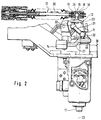
- a switch housing part 10 is in the form of an end cover with a central passage 6 for a selector shaft 11 and with a vertically - in the installed position down - outgoing bearing bracket 7, which is rotatable by a roller bearing arrangement in the passage 6 and at the lower end of the bearing bracket 7 and Axially displaceable with respect to its axis of rotation 23-23 with respect to the shift housing part 10 mounted shift shaft 11 in the area of the bearing bracket 7 is provided with a shift finger 8 for actuating shift rods, not shown, which is used to actuate the usual gear clutches for coupling a loose wheel to its transmission shaft are.
- the shift finger 8 can be actuated to engage and disengage the gears (gear clutches) by means of a shift lever 12, which is firmly connected to the upper end 9 of the shift shaft 11 and has a joint half 16 of a joint 15 in the form of a ball head, which fits into the corresponding ball socket 29 of the other joint half 18 of the joint 15 engages, which is used to link a flexible switching cable 17 for transmitting tensile and compressive forces to the shift lever 12.
- the shift cable 17 is caused by a manual shift lever 13 to engage and disengage in the direction of the arrow 20, the shift cable 17 being connected to the joint half 18 with the interposition of an annular damping member 19 lying in the power flow of the shifting forces.
- a boom 14 holding an additional mass 14 at its free end 21 is on a support 22 of the switch housing part 10 um a pivot axis 24-24 parallel to the axis of rotation 23-23 is pivotable stored and supported with its weight.
- a handlebar 31 For the kinematic connection of gear lever 12 and bracket 21 is a handlebar 31 with the interposition of a ball joint 32 used.
- the manual shift lever 13 is through a ball joint 25 with the Switching cable 17 connected, one joint half 26 in the form a ball head connected to the manual shift lever 13 in a fixed manner and in the corresponding ball socket 30 of the other Joint half 27 engages.
- the manual shift lever 13 is such in a known manner first pivot axis pivotably mounted on a bearing block 33, that these pivotal movements in the engaging and disengaging movements 20 of the switching cable 17 are implemented.
- the switching cable 17 is with the joint half 27 with the interposition of one in the power flow of the engagement and disengagement forces lying annular elastic Attenuator 28 connected.
- the shift finger 8 is for coupling to the respective shift rod in the longitudinal directions of the axis of rotation 23-23 by a double-armed selector lever 34, which is on the switch housing part 10 about a pivot axis perpendicular to the axis of rotation 23-23 35-35 is pivotally mounted.
- One lever arm 36 of the selector lever 34 is connected by a hinge - of which only one hinge pin 38 is shown - via a flexible dialing cable for transmission of tensile and compressive forces also kinematically connected to the manual shift lever 13.
- the manual shift lever 13 is pivotable about a second pivot axis mounted on the bearing block 33 so that pivoting movements around the first swivel axis for actuating only the switching cable 17 - on the other hand about the second pivot axis for actuation only lead the selector cable that is no longer shown.
- the second lever arm 37 of the selector lever 34 is through a joint arrangement 39 - what pivotal movements in reciprocating Movements converted - connected to the shift shaft 11.
- both the additional mass 14 and the attenuators 19 and 28 exclusively on that Circuit system for engaging and disengaging the gears for effect brought - from the dialing system to choose one of the Shift rods (shift lanes), however, completely decoupled.
Landscapes
- Engineering & Computer Science (AREA)
- General Engineering & Computer Science (AREA)
- Mechanical Engineering (AREA)
- Gear-Shifting Mechanisms (AREA)
- Arrangement Or Mounting Of Control Devices For Change-Speed Gearing (AREA)
Applications Claiming Priority (2)
| Application Number | Priority Date | Filing Date | Title |
|---|---|---|---|
| DE19636506 | 1996-09-09 | ||
| DE19636506A DE19636506B4 (de) | 1996-09-09 | 1996-09-09 | Schaltvorrichtung für ein Gangwechselgetriebe eines Kraftfahrzeuges |
Publications (3)
| Publication Number | Publication Date |
|---|---|
| EP0828097A2 true EP0828097A2 (fr) | 1998-03-11 |
| EP0828097A3 EP0828097A3 (fr) | 1998-10-21 |
| EP0828097B1 EP0828097B1 (fr) | 2002-02-13 |
Family
ID=7805008
Family Applications (1)
| Application Number | Title | Priority Date | Filing Date |
|---|---|---|---|
| EP97115075A Expired - Lifetime EP0828097B1 (fr) | 1996-09-09 | 1997-08-30 | Dispositif de commande d'une boíte de vitesses de véhicule automobile |
Country Status (6)
| Country | Link |
|---|---|
| US (1) | US5927151A (fr) |
| EP (1) | EP0828097B1 (fr) |
| JP (1) | JP3030694B2 (fr) |
| KR (1) | KR19980024432A (fr) |
| BR (1) | BR9704673A (fr) |
| DE (2) | DE19636506B4 (fr) |
Cited By (7)
| Publication number | Priority date | Publication date | Assignee | Title |
|---|---|---|---|---|
| DE19901813A1 (de) * | 1999-01-19 | 2000-07-20 | Volkswagen Ag | Schaltvorrichtung, insbesondere für ein Fahrzeuggetriebe |
| FR2822213A1 (fr) * | 2001-03-13 | 2002-09-20 | Ina Schaeffler Kg | Dispositif d'actionnement d'une boite de vitesses |
| WO2007068556A1 (fr) * | 2005-12-14 | 2007-06-21 | Schaeffler Kg | Systeme de palier pour le montage d'une masse supplementaire |
| WO2008052865A1 (fr) * | 2006-10-28 | 2008-05-08 | Schaeffler Kg | Liaison de transmission entre un arbre de changement de vitesse et une masse supplémentaire |
| DE102007032681A1 (de) * | 2007-07-13 | 2009-01-22 | GM Global Technology Operations, Inc., Detroit | Betätigungsvorrichtung für ein Schaltgetriebe eines Kraftfahrzeuges |
| WO2012175851A1 (fr) * | 2011-06-23 | 2012-12-27 | Renault S.A.S. | Dispositif d'actionnement d'une boîte de vitesses avec masse d'inertie clipsée |
| DE102012206992A1 (de) * | 2012-04-27 | 2013-10-31 | Zf Friedrichshafen Ag | Rastiervorrichtung |
Families Citing this family (30)
| Publication number | Priority date | Publication date | Assignee | Title |
|---|---|---|---|---|
| US6026698A (en) * | 1996-08-13 | 2000-02-22 | Weston; Bevan | Transmission and shift mechanism |
| EP0869048B1 (fr) * | 1997-03-31 | 2005-12-07 | Honda Giken Kogyo Kabushiki Kaisha | Dispositif actuateur de changement de vitesse pour véhicule |
| JP3862124B2 (ja) * | 1998-09-30 | 2006-12-27 | スズキ株式会社 | 変速機の潤滑構造 |
| GB9923611D0 (en) * | 1999-10-07 | 1999-12-08 | Rover Group | A selector damper arrangement |
| KR100410905B1 (ko) * | 2001-05-03 | 2003-12-18 | 현대자동차주식회사 | 변속 케이블 어셈블리 |
| KR100428166B1 (ko) * | 2001-11-28 | 2004-04-28 | 현대자동차주식회사 | 차량의 변속조작기구 |
| JP2003301942A (ja) * | 2002-02-08 | 2003-10-24 | Calsonic Kansei Corp | 車両用自動変速装置 |
| FR2840659B1 (fr) * | 2002-06-05 | 2004-12-10 | Peugeot Citroen Automobiles Sa | Agencement d'une masse d'inertie sur un axe de rotation et boite de vitesses comportant un tel agencement |
| US20060053943A1 (en) * | 2004-06-28 | 2006-03-16 | Honda Motor Co., Ltd. | Rigidity tuning structure of transmission cable for manual transmission |
| SE527630C2 (sv) * | 2004-09-07 | 2006-04-25 | Volvo Lastvagnar Ab | Dämpmassa för ökad växlingskomfort |
| JP4560831B2 (ja) * | 2004-09-30 | 2010-10-13 | マツダ株式会社 | 変速機 |
| JP4600809B2 (ja) * | 2004-09-30 | 2010-12-22 | マツダ株式会社 | ケーブル式チェンジ装置 |
| FR2882122B1 (fr) * | 2005-02-17 | 2008-10-10 | Renault Sas | Dispositif de commande de passage de vitesses |
| SE528898C2 (sv) * | 2005-12-16 | 2007-03-06 | Gm Global Tech Operations Inc | Manövreringsmekanism för manuell växellåda |
| DE102005062170A1 (de) * | 2005-12-23 | 2007-06-28 | Schaeffler Kg | Schaltgewicht |
| JP2007177899A (ja) * | 2005-12-28 | 2007-07-12 | Yamaha Motor Co Ltd | 鞍乗型車両 |
| JP4795835B2 (ja) * | 2006-04-07 | 2011-10-19 | 本田技研工業株式会社 | 油圧駆動車両 |
| DE102006024628A1 (de) * | 2006-05-26 | 2007-11-29 | Schaeffler Kg | Schaltvorrichtung für ein Getriebe |
| DE102006024627A1 (de) | 2006-05-26 | 2007-11-29 | Schaeffler Kg | Schaltvorrichtung für ein Getriebe |
| DE102007042212A1 (de) | 2007-09-05 | 2009-03-12 | Schaeffler Kg | Schalteinheit für ein Schaltgetriebe eines Kraftfahrzeugs |
| DE102009057290A1 (de) | 2009-12-07 | 2011-06-09 | Schaeffler Technologies Gmbh & Co. Kg | Dämpfungsvorrichtung zur Dämpfung von Schwingungen in einem Getriebe |
| DE102010032250A1 (de) | 2010-07-26 | 2012-01-26 | Schaeffler Technologies Gmbh & Co. Kg | Schaltvorrichtung für ein Getriebe |
| DE102011014071A1 (de) * | 2011-03-16 | 2012-09-20 | GM Global Technology Operations LLC (n. d. Gesetzen des Staates Delaware) | Schaltbetätigung |
| KR20130017724A (ko) * | 2011-08-11 | 2013-02-20 | 현대자동차주식회사 | 변속기의 변속 조작장치 |
| DE102011111913A1 (de) | 2011-08-30 | 2013-02-28 | Daimler Ag | Schaltmodul |
| KR101406517B1 (ko) * | 2012-11-09 | 2014-06-13 | 현대자동차주식회사 | 차량용 변속 조작기구 |
| DE102013006084A1 (de) | 2013-04-09 | 2014-10-09 | Daimler Ag | Handschaltvorrichtung für ein Handschaltgetriebe eines Kraftfahrzeugs |
| DE102014201477A1 (de) * | 2014-01-28 | 2015-07-30 | Zf Friedrichshafen Ag | Übersetzungsvorrichtung und Verfahren zum Übersetzen eines Betätigungswinkels eines Wählhebels für eine Schaltbetätigung für ein Fahrzeuggetriebe |
| JP6327261B2 (ja) * | 2016-01-28 | 2018-05-23 | トヨタ自動車株式会社 | 車両の手動変速機 |
| US10969006B2 (en) * | 2019-07-18 | 2021-04-06 | Zoomlion Heavy Industry Na, Inc. | Electro-mechanical transmission shifter |
Family Cites Families (16)
| Publication number | Priority date | Publication date | Assignee | Title |
|---|---|---|---|---|
| DE1755476B2 (de) * | 1968-05-14 | 1979-01-04 | Daimler-Benz Ag, 7000 Stuttgart | Vorrichtung zur Schwingungsisolierung von Schaltgestängen bei Kraftfahrzeug-Wechselgetrieben |
| JPS5813926B2 (ja) * | 1975-12-28 | 1983-03-16 | トヨタ自動車株式会社 | トランスミツシヨンコントロ−ルキコウ |
| GB2027115B (en) * | 1978-08-04 | 1982-09-08 | British Leyland Cars Ltd | Ball joints |
| US4355543A (en) * | 1980-08-20 | 1982-10-26 | Toyota Jidosha Kogyo Kabushiki Kaisha | Device for supporting a shift lever in a manual transmission for an automobile |
| JPS57186525A (en) * | 1981-05-13 | 1982-11-17 | Nissan Motor Co Ltd | Supporting construction of control lever of floor shift type |
| US4458549A (en) * | 1981-08-12 | 1984-07-10 | Toyota Jidosha Kogyo Kabushiki Kaisha | Select return mechanism for a transmission |
| DE3784274T2 (de) * | 1986-07-04 | 1993-08-26 | Toyota Motor Co Ltd | Servogangschaltvorrichtung fuer ein handgeschaltetes getriebe. |
| DE3839319A1 (de) * | 1987-11-30 | 1989-07-06 | Remote Control Systems Rcs | Getriebeschaltgeraet fuer kraftfahrzeuge |
| DE3932815A1 (de) * | 1989-09-30 | 1991-04-11 | Diehl Gmbh & Co | Kraftuebertragungsgelenk fuer das schaltgestaenge eines kraftfahrzeuggetriebes |
| JPH03119654U (fr) * | 1990-03-22 | 1991-12-10 | ||
| JP2648262B2 (ja) * | 1991-12-10 | 1997-08-27 | 株式会社クボタ | 作業車の変速操作構造 |
| DE4231248C2 (de) * | 1992-02-01 | 1995-04-27 | Volkswagen Ag | Gangschalteinrichtung für ein Kraftfahrzeug |
| FR2693808B1 (fr) * | 1992-07-17 | 1994-09-16 | Renault | Dispositif d'assistance mécanique au passage des vitesses. |
| JP2964850B2 (ja) * | 1993-08-31 | 1999-10-18 | 三菱自動車工業株式会社 | 車両用手動変速機 |
| DE4427076C1 (de) * | 1994-07-30 | 1996-01-18 | Ford Werke Ag | Innere Schaltvorrichtung für Wechselgetriebe von Kraftfahrzeugen |
| DE19523141C2 (de) * | 1995-06-28 | 1997-04-17 | Daimler Benz Ag | Schaltvorrichtung für ein Gangwechselgetriebe eines Kraftfahrzeuges |
-
1996
- 1996-09-09 DE DE19636506A patent/DE19636506B4/de not_active Expired - Fee Related
-
1997
- 1997-08-30 EP EP97115075A patent/EP0828097B1/fr not_active Expired - Lifetime
- 1997-08-30 DE DE59706365T patent/DE59706365D1/de not_active Expired - Lifetime
- 1997-09-05 JP JP9279288A patent/JP3030694B2/ja not_active Expired - Lifetime
- 1997-09-09 BR BR9704673A patent/BR9704673A/pt not_active IP Right Cessation
- 1997-09-09 US US08/926,033 patent/US5927151A/en not_active Expired - Lifetime
- 1997-09-09 KR KR1019970046247A patent/KR19980024432A/ko not_active Abandoned
Cited By (12)
| Publication number | Priority date | Publication date | Assignee | Title |
|---|---|---|---|---|
| DE19901813A1 (de) * | 1999-01-19 | 2000-07-20 | Volkswagen Ag | Schaltvorrichtung, insbesondere für ein Fahrzeuggetriebe |
| DE19901813B4 (de) * | 1999-01-19 | 2009-02-05 | Volkswagen Ag | Schaltvorrichtung für ein Fahrzeuggetriebe |
| FR2822213A1 (fr) * | 2001-03-13 | 2002-09-20 | Ina Schaeffler Kg | Dispositif d'actionnement d'une boite de vitesses |
| WO2007068556A1 (fr) * | 2005-12-14 | 2007-06-21 | Schaeffler Kg | Systeme de palier pour le montage d'une masse supplementaire |
| WO2008052865A1 (fr) * | 2006-10-28 | 2008-05-08 | Schaeffler Kg | Liaison de transmission entre un arbre de changement de vitesse et une masse supplémentaire |
| DE102007032681A1 (de) * | 2007-07-13 | 2009-01-22 | GM Global Technology Operations, Inc., Detroit | Betätigungsvorrichtung für ein Schaltgetriebe eines Kraftfahrzeuges |
| WO2012175851A1 (fr) * | 2011-06-23 | 2012-12-27 | Renault S.A.S. | Dispositif d'actionnement d'une boîte de vitesses avec masse d'inertie clipsée |
| FR2976994A1 (fr) * | 2011-06-23 | 2012-12-28 | Renault Sa | Dispositif d'actionnement d'une boite de vitesses avec masse d'inertie clipsee |
| CN103688088A (zh) * | 2011-06-23 | 2014-03-26 | 雷诺股份公司 | 用于致动带有夹紧式惯性质量块的变速箱的装置 |
| CN103688088B (zh) * | 2011-06-23 | 2015-11-25 | 雷诺股份公司 | 用于致动带有夹紧式惯性质量块的变速箱的装置 |
| RU2591116C2 (ru) * | 2011-06-23 | 2016-07-10 | Рено С.А.С. | Приводное устройство коробки передач с защелкивающимся инерционным балансиром |
| DE102012206992A1 (de) * | 2012-04-27 | 2013-10-31 | Zf Friedrichshafen Ag | Rastiervorrichtung |
Also Published As
| Publication number | Publication date |
|---|---|
| DE19636506B4 (de) | 2005-08-11 |
| DE19636506A1 (de) | 1998-03-12 |
| BR9704673A (pt) | 1999-05-25 |
| EP0828097B1 (fr) | 2002-02-13 |
| DE59706365D1 (de) | 2002-03-21 |
| JP3030694B2 (ja) | 2000-04-10 |
| EP0828097A3 (fr) | 1998-10-21 |
| MX9706849A (es) | 1998-03-31 |
| KR19980024432A (ko) | 1998-07-06 |
| JPH1089470A (ja) | 1998-04-07 |
| US5927151A (en) | 1999-07-27 |
Similar Documents
| Publication | Publication Date | Title |
|---|---|---|
| EP0828097B1 (fr) | Dispositif de commande d'une boíte de vitesses de véhicule automobile | |
| DE19546547C1 (de) | Schaltvorrichtung für ein Gangwechselgetriebe eines Kraftfahrzeuges | |
| DE3636978C2 (fr) | ||
| DE68908925T2 (de) | Fernbetätigungseinrichtung. | |
| DE10005328A1 (de) | Schaltvorrichtung für ein Automatikgetriebe | |
| DE4020608C2 (de) | Schaltmechanismus für ein Geschwindigkeitswechselgetriebe | |
| DE102005062167B3 (de) | Schalthebel mit Betätigungseinrichtung für eine Rückwärtsgangsperre | |
| DE2823460A1 (de) | Pedalanordnung zur steuerung von motor und getriebe bei kraftfahrzeugen | |
| DE2062691A1 (de) | Schaltvorrichtung eines Zahnräderwechselgetriebes, insbesondere für Kraftfahrzeuge | |
| EP1262692A2 (fr) | Transmission | |
| DE4308637A1 (de) | Schaltvorrichtung für ein Handschaltgetriebe eines Kraftfahrzeuges | |
| DE3839319C2 (fr) | ||
| DE3216688A1 (de) | Abstuetzvorrichtung fuer einen am boden angeordneten getriebeschalthebel eines kraftfahrzeuges | |
| DE102005060933B3 (de) | Wählhebel, insbesondere für ein Kraftfahrzeug | |
| EP1611375A2 (fr) | Changement de vitesses du type shift-by-wire avec position p | |
| EP1531290B1 (fr) | Dispositif de sélection de vitesse | |
| DE69601285T2 (de) | Fahrzeug-Gangschalthebel mit Kraftaufnehmer | |
| EP1291560B1 (fr) | Dispositif de changement de rapports à commande assistée | |
| WO2013030232A1 (fr) | Dispositif de changement de vitesse | |
| DE10322037A1 (de) | Schaltbetätigungssystem | |
| EP1267240A1 (fr) | Changement de vitesse pour une boíte de vitesses manuelle d'un véhicule automobile | |
| WO2013068187A1 (fr) | Dispositif de changement de vitesse assurant le passage des vitesses dans une boîte de vitesses mécanique d'un véhicule | |
| DE3340729A1 (de) | Steuervorrichtung fuer eine kupplung und ein getriebe in einem fahrzeug | |
| EP1213509B1 (fr) | Mécanisme de changement de vitesses pour transmission de véhicule | |
| DE102004054258B3 (de) | Betätigungsvorrichtung zur Steuerung des Gangwechsels eines Kraftfahrzeuggetriebes |
Legal Events
| Date | Code | Title | Description |
|---|---|---|---|
| PUAI | Public reference made under article 153(3) epc to a published international application that has entered the european phase |
Free format text: ORIGINAL CODE: 0009012 |
|
| AK | Designated contracting states |
Kind code of ref document: A2 Designated state(s): DE ES FR GB IT SE |
|
| AX | Request for extension of the european patent |
Free format text: AL;LT;LV;RO;SI |
|
| PUAL | Search report despatched |
Free format text: ORIGINAL CODE: 0009013 |
|
| AK | Designated contracting states |
Kind code of ref document: A3 Designated state(s): AT BE CH DE DK ES FI FR GB GR IE IT LI LU MC NL PT SE |
|
| AX | Request for extension of the european patent |
Free format text: AL;LT;LV;RO;SI |
|
| 17P | Request for examination filed |
Effective date: 19980922 |
|
| RAP1 | Party data changed (applicant data changed or rights of an application transferred) |
Owner name: DAIMLERCHRYSLER AG |
|
| AKX | Designation fees paid |
Free format text: DE ES FR GB IT SE |
|
| 17Q | First examination report despatched |
Effective date: 20001116 |
|
| GRAG | Despatch of communication of intention to grant |
Free format text: ORIGINAL CODE: EPIDOS AGRA |
|
| GRAG | Despatch of communication of intention to grant |
Free format text: ORIGINAL CODE: EPIDOS AGRA |
|
| GRAH | Despatch of communication of intention to grant a patent |
Free format text: ORIGINAL CODE: EPIDOS IGRA |
|
| GRAH | Despatch of communication of intention to grant a patent |
Free format text: ORIGINAL CODE: EPIDOS IGRA |
|
| GRAA | (expected) grant |
Free format text: ORIGINAL CODE: 0009210 |
|
| REG | Reference to a national code |
Ref country code: GB Ref legal event code: IF02 |
|
| AK | Designated contracting states |
Kind code of ref document: B1 Designated state(s): DE ES FR GB IT SE |
|
| PG25 | Lapsed in a contracting state [announced via postgrant information from national office to epo] |
Ref country code: GB Free format text: LAPSE BECAUSE OF FAILURE TO SUBMIT A TRANSLATION OF THE DESCRIPTION OR TO PAY THE FEE WITHIN THE PRESCRIBED TIME-LIMIT Effective date: 20020213 |
|
| REF | Corresponds to: |
Ref document number: 59706365 Country of ref document: DE Date of ref document: 20020321 |
|
| PG25 | Lapsed in a contracting state [announced via postgrant information from national office to epo] |
Ref country code: SE Free format text: LAPSE BECAUSE OF FAILURE TO SUBMIT A TRANSLATION OF THE DESCRIPTION OR TO PAY THE FEE WITHIN THE PRESCRIBED TIME-LIMIT Effective date: 20020513 |
|
| ET | Fr: translation filed | ||
| GBV | Gb: ep patent (uk) treated as always having been void in accordance with gb section 77(7)/1977 [no translation filed] |
Effective date: 20020213 |
|
| PG25 | Lapsed in a contracting state [announced via postgrant information from national office to epo] |
Ref country code: ES Free format text: LAPSE BECAUSE OF FAILURE TO SUBMIT A TRANSLATION OF THE DESCRIPTION OR TO PAY THE FEE WITHIN THE PRESCRIBED TIME-LIMIT Effective date: 20020829 |
|
| PLBE | No opposition filed within time limit |
Free format text: ORIGINAL CODE: 0009261 |
|
| STAA | Information on the status of an ep patent application or granted ep patent |
Free format text: STATUS: NO OPPOSITION FILED WITHIN TIME LIMIT |
|
| 26N | No opposition filed |
Effective date: 20021114 |
|
| PGFP | Annual fee paid to national office [announced via postgrant information from national office to epo] |
Ref country code: FR Payment date: 20050812 Year of fee payment: 9 |
|
| PGFP | Annual fee paid to national office [announced via postgrant information from national office to epo] |
Ref country code: IT Payment date: 20060831 Year of fee payment: 10 |
|
| REG | Reference to a national code |
Ref country code: FR Ref legal event code: ST Effective date: 20070430 |
|
| PG25 | Lapsed in a contracting state [announced via postgrant information from national office to epo] |
Ref country code: FR Free format text: LAPSE BECAUSE OF NON-PAYMENT OF DUE FEES Effective date: 20060831 |
|
| PG25 | Lapsed in a contracting state [announced via postgrant information from national office to epo] |
Ref country code: IT Free format text: LAPSE BECAUSE OF NON-PAYMENT OF DUE FEES Effective date: 20070830 |
|
| PGFP | Annual fee paid to national office [announced via postgrant information from national office to epo] |
Ref country code: DE Payment date: 20131031 Year of fee payment: 17 |
|
| REG | Reference to a national code |
Ref country code: DE Ref legal event code: R119 Ref document number: 59706365 Country of ref document: DE |
|
| REG | Reference to a national code |
Ref country code: DE Ref legal event code: R119 Ref document number: 59706365 Country of ref document: DE Effective date: 20150303 |
|
| PG25 | Lapsed in a contracting state [announced via postgrant information from national office to epo] |
Ref country code: DE Free format text: LAPSE BECAUSE OF NON-PAYMENT OF DUE FEES Effective date: 20150303 |