EP0828267A2 - Schutzschalter mit Zwangstrennung - Google Patents
Schutzschalter mit Zwangstrennung Download PDFInfo
- Publication number
- EP0828267A2 EP0828267A2 EP97111531A EP97111531A EP0828267A2 EP 0828267 A2 EP0828267 A2 EP 0828267A2 EP 97111531 A EP97111531 A EP 97111531A EP 97111531 A EP97111531 A EP 97111531A EP 0828267 A2 EP0828267 A2 EP 0828267A2
- Authority
- EP
- European Patent Office
- Prior art keywords
- circuit breaker
- current circuit
- residual current
- propellant charge
- pivot axis
- Prior art date
- Legal status (The legal status is an assumption and is not a legal conclusion. Google has not performed a legal analysis and makes no representation as to the accuracy of the status listed.)
- Granted
Links
- 238000006073 displacement reaction Methods 0.000 claims abstract description 7
- 239000003380 propellant Substances 0.000 claims description 18
- 239000012777 electrically insulating material Substances 0.000 claims description 4
- 230000001960 triggered effect Effects 0.000 abstract description 2
- 239000000969 carrier Substances 0.000 abstract 2
- 239000011810 insulating material Substances 0.000 abstract 1
- 239000002184 metal Substances 0.000 abstract 1
- 238000012360 testing method Methods 0.000 description 8
- 238000000926 separation method Methods 0.000 description 6
- 230000006870 function Effects 0.000 description 4
- 230000007774 longterm Effects 0.000 description 2
- 238000011990 functional testing Methods 0.000 description 1
- 238000009434 installation Methods 0.000 description 1
- 230000001681 protective effect Effects 0.000 description 1
- 230000009993 protective function Effects 0.000 description 1
- 230000004043 responsiveness Effects 0.000 description 1
- 230000035945 sensitivity Effects 0.000 description 1
Images

Classifications
-
- H—ELECTRICITY
- H01—ELECTRIC ELEMENTS
- H01H—ELECTRIC SWITCHES; RELAYS; SELECTORS; EMERGENCY PROTECTIVE DEVICES
- H01H71/00—Details of the protective switches or relays covered by groups H01H73/00 - H01H83/00
- H01H71/10—Operating or release mechanisms
- H01H71/12—Automatic release mechanisms with or without manual release
-
- H—ELECTRICITY
- H01—ELECTRIC ELEMENTS
- H01H—ELECTRIC SWITCHES; RELAYS; SELECTORS; EMERGENCY PROTECTIVE DEVICES
- H01H83/00—Protective switches, e.g. circuit-breaking switches, or protective relays operated by abnormal electrical conditions otherwise than solely by excess current
- H01H83/14—Protective switches, e.g. circuit-breaking switches, or protective relays operated by abnormal electrical conditions otherwise than solely by excess current operated by imbalance of two or more currents or voltages, e.g. for differential protection
Definitions
- the invention relates to a residual current circuit breaker with a Housing with input and output terminals, in which a Function chain consisting of a summation current transformer, a trip relay and a switching kinematics for contact arrangements are provided are, each contact arrangement an electrically conductive, pivoted contact lever, the conductive with an output terminal is connected, and a stationary Has counter contact.
- Such residual current circuit breakers have the task of one Protection against excessive contact voltages as well as a fire to provide protection. This requires great reliability with high sensitivity.
- the one available Tripping power with such residual current circuit breakers, through the fault current actually flowing to earth is determined only on the order of a few 10 ⁇ m VA. Because of this low tripping power especially with long-term use the problem that it can lead to tripping failure can come.
- Residual current circuit breaker a test button with which the function of the switching device can be checked on a regular basis in order to timely if necessary, the residual current circuit breaker by a to replace new ones.
- the invention is accordingly based on the object of a residual current circuit breaker the genus mentioned in the beginning to further develop that when a fault current flows despite failure of a component of the functional chain is reliable Separation function is realized.
- each pivotable contact lever on a pivot axis made of an electrically insulating material is only electrically conductive in the pivot lever bearing area and that when a fault current occurs and at the same time Failure of a component of the functional chain axially for separation the electrical connection in the swivel lever bearing area is relocatable.
- the solution according to the invention is advantageous in electrical Systems achieved a reliability of the protective switching devices, which previously seemed to be an illusion. Also need Residual current circuit breakers constructed according to the invention none Test button, since no test circuit is required.
- Another advantage is that due to the achievable reliability no regular check, for example on the part of of the technical surveillance association, more is needed and therefore Test costs can be saved.
- the axial displacement provided in the invention can be after all known mechanical and electromechanical principles be made. It is particularly advantageous in terms of Size and responsiveness if over the axial displacement provided an electrically ignitable propellant charge is, the propellant charge preferably on an end Attacks the end of the swivel axis.
- each a half propellant receiving portion is formed and preferably the receiving sections are guided on a tubular element, in which the propellant charge is arranged and the one preferably central wall hole for the entry of an electrical ignition device has, with the propellant charge on the ends of the axles for axial displacement are acted upon.
- a timer is preferably provided, which the electrical Ignition device controls.
- the residual current circuit breaker triggers in the usual way when a fault current flows.
- a component in the function chain fails in the form that the trigger time specified by the timer exceeded is an electrical ignition of the propellant charge the electrical ignition device with the result that all previously electrically conductive pivot lever bearing areas due to the axial displacement of the swivel axis are inevitably separated because the swivel levers now only on an electrically insulated part of the swivel axis and thus a conductive connection to the output terminal is interrupted.
- the arrangement is such that the pivot axis with its conductive sections like a Switch acts. This is also advantageous the possibility of errors of "welded contacts" taken into account, because a forced separation is not in their contact area he follows.
- the swivel axis is divided approximately in the middle of the switching device is, it is conveniently possible at the separation point to accommodate the propellant charge, with reinforced for this Provided ends to form the propellant charge receiving sections are, which encompass the propellant charge on all sides and in which Starting position two halves of a closed receiving chamber form for the propellant charge.
- the two Halves of the receiving chamber sections and thus the pivot axis moved away from each other in the axial direction being advantageous the energy required for the propellant charge is only low needs to be, since it is only necessary, the frictional force to overcome in the field of contact arrangements. After the forced separation has taken place, there is certainly an interruption of the circuit without the risk of a given improper restart of the switching device is.
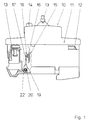
- Fig. 1 is a schematic side view of the residual current circuit breaker 10, which has a housing 11, at which an input terminal 12 and an output terminal 13 is provided for connection in front of the electrical line.
- a switch toggle 13 is provided, one of which is spaced apart Test button 14 protrudes from the housing 11.
- a functional chain not shown from a summation current transformer, a trip relay and a switching kinematics for switch contact arrangements are provided.
- 1 shows in section a contact arrangement 15 with a stationary contact 16 and an electrically conductive Contact lever 17 with contact 18 and a storage area 19, in which, as can be seen in FIG. 2, the contact lever 17 is mounted on a pivot axis 20.
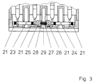
- the pivot axis 20 consists of an electrically insulating material and is in Area of the storage areas shown in FIG. 2 with electrical conductive portions 21 formed which is an electrically conductive Connection to one connected to the output terminal 13 Pivot axis bearing 22 forms.
- the pivot axis is half divided and consists of a left section 23 and one right section 24. In the division area they have each other pointing ends of the pivot axis half receiving chambers 25 or 26, which are guided on a tubular element 27 are.
- the tubular element 27 is also used for receiving a drive line 28, which by means of electrical ignition an ignition device, not shown, by a central wall bore 29 of the tubular element 27 takes place, from the side pipe openings onto the receiving chamber sections 25 and 26 acts as shown in Fig. 3.
- Fig. 3 shows the part of the residual current circuit breaker shown in Fig. 2 10 after triggering, which is not shown electrical ignition device via a likewise not shown Timer is controlled for testing failure of components of the functional chain is provided.
- Out Fig. 3 can be seen that after ignition, the bearing areas 19th the contact lever 17 is no longer in conductive contact with the electrically conductive sections 21, but only with the adjoining sections 23 and 24 from one electrically insulating material. This will achieved a forced separation quickly and effectively.
Landscapes
- Breakers (AREA)
Abstract
Description
- Fig. 1
- eine teilweise weggeschnittene Seitenansicht eines Ausführungsbeispiels eines Fehlerstromschutzschalters gemäß der Erfindung;
- Fig. 2
- eine Seitenansicht in Fig. 1 von links, wobei der Bereich der Schwenkhebellagerung und der Schwenkachse geschnitten ist; und
- Fig. 3
- eine Schnittansicht gemäß Fig. 2, jedoch nach ausgelöster Treibladung.
Claims (7)
- Fehlerstromschutzschalter (10) mit einem Ein- und Ausgangsklemmen (12 bzw. 13) aufweisenden Gehäuse (11), in dem eine Funktionskette aus einem Summenstromwandler, einem Auslöserelais sowie einer Schaltkinematik für Kontaktanordnungen (15) vorgesehen sind, wobei jede Kontaktanordnung (15) einen elektrisch leitenden, schwenkbar gelagerten Kontakthebel (17), der leitend mit einer Ausgangsklemme (13) verbunden ist, sowie einen stationären Kontakt (16) aufweist,
dadurch gekennzeichnet,
daß jeder schwenkbare Kontakthebel (17) an einer Schwenkachse (20) aus einem elektrisch isolierenden Werkstoff gelagert ist, die nur im Schwenkhebellagerbereich (19) elektrisch leitend ist und bei Auftreten eines Fehlerstroms und gleichzeitigem Versagen eines Bauteils der Funktionskette axial zur Trennung der elektrischen Verbindung im Schwenkhebellagerbereich (19) verlagerbar ist. - Fehlerstromschutzschalter nach Anspruch 1,
dadurch gekennzeichnet,
daß für die axiale Verlagerung der Schwenkachse (20) eine elektrisch zündbare Treibladung (28) vorgesehen ist. - Fehlerstromschutzschalter nach Anspruch 2,
dadurch gekennzeichnet,
daß die Treibladung (28) an ein stirnseitiges Ende der Schwenkachse (20) angreift. - Fehlerstromschutzschalter nach Anspruch 2,
dadurch gekennzeichnet,
daß die Schwenkachse (20) quergeteilt ist, wobei an den zueinander weisenden Enden der Schwenkachse (23, 24) jeweils ein radial erweiterter hälftiger Treibladungs-Aufnahmeabschnitt (25, 26) gebildet ist. - Fehlerstromschutzschalter nach Anspruch 4,
dadurch gekennzeichnet,
daß die hälftigen Treibladungs-Aufnahmeabschnitte (25, 26) an einem rohrförmigen Element (27) geführt sind, in dem die Treibladung (28) angeordnet ist und das eine vorzugsweise mittige Wandbohrung (29) für den Eintritt einer elektrischen Zündeinrichtung aufweist, wobei bei Zündung der Treibladung (28) an beiden Enden die Achsabschnitte (23, 24) zur axialen Auseinanderverschiebung gleichmäßig beaufschlagbar sind. - Fehlerstromschutzschalter nach einem der Ansprüche 2 bis 5,
dadurch gekennzeichnet,
daß die elektrische Zündeinrichtung über ein Zeitglied steuerbar ist, das für das Prüfen des Versagens von Bauteilen der Funktionskette vorgesehen ist. - Fehlerstromschutzschalter nach Anspruch 6,
dadurch gekennzeichnet,
daß das Zeitglied auf eine vorgegebene Auslösezeit des Fehlerstromschutzschalters abgestimmt ist.
Applications Claiming Priority (2)
| Application Number | Priority Date | Filing Date | Title |
|---|---|---|---|
| DE19632462A DE19632462B4 (de) | 1996-08-12 | 1996-08-12 | Schutzschalter mit Zwangstrennung |
| DE19632462 | 1996-08-12 |
Publications (3)
| Publication Number | Publication Date |
|---|---|
| EP0828267A2 true EP0828267A2 (de) | 1998-03-11 |
| EP0828267A3 EP0828267A3 (de) | 1998-12-23 |
| EP0828267B1 EP0828267B1 (de) | 2000-01-05 |
Family
ID=7802423
Family Applications (1)
| Application Number | Title | Priority Date | Filing Date |
|---|---|---|---|
| EP97111531A Expired - Lifetime EP0828267B1 (de) | 1996-08-12 | 1997-07-08 | Schutzschalter mit Zwangstrennung |
Country Status (4)
| Country | Link |
|---|---|
| EP (1) | EP0828267B1 (de) |
| AT (1) | ATE188573T1 (de) |
| DE (1) | DE19632462B4 (de) |
| ES (1) | ES2143271T3 (de) |
Families Citing this family (1)
| Publication number | Priority date | Publication date | Assignee | Title |
|---|---|---|---|---|
| DE19735416A1 (de) * | 1997-08-14 | 1999-02-18 | Siemens Ag | Schutzeinrichtung |
Family Cites Families (4)
| Publication number | Priority date | Publication date | Assignee | Title |
|---|---|---|---|---|
| DE1068801B (de) * | 1959-11-12 | |||
| DE3823098A1 (de) * | 1988-07-07 | 1990-01-11 | Siemens Ag | Einrichtung zum schutz vor fehlerstroemen |
| FR2709205B1 (fr) * | 1993-08-17 | 1995-10-20 | Merlin Gerin | Interrupteur différentiel tétrapolaire. |
| DE4337254B4 (de) * | 1993-11-02 | 2005-05-19 | Aeg Niederspannungstechnik Gmbh & Co Kg | Fehlerstrommodul, der mit Leitungsschutzschaltern zusammensetzbar ist |
-
1996
- 1996-08-12 DE DE19632462A patent/DE19632462B4/de not_active Expired - Fee Related
-
1997
- 1997-07-08 AT AT97111531T patent/ATE188573T1/de active
- 1997-07-08 EP EP97111531A patent/EP0828267B1/de not_active Expired - Lifetime
- 1997-07-08 ES ES97111531T patent/ES2143271T3/es not_active Expired - Lifetime
Also Published As
| Publication number | Publication date |
|---|---|
| DE19632462A1 (de) | 1998-02-19 |
| EP0828267A3 (de) | 1998-12-23 |
| ES2143271T3 (es) | 2000-05-01 |
| ATE188573T1 (de) | 2000-01-15 |
| DE19632462B4 (de) | 2005-05-04 |
| EP0828267B1 (de) | 2000-01-05 |
Similar Documents
| Publication | Publication Date | Title |
|---|---|---|
| EP0174904B1 (de) | Kontaktanordnung für Niederspannungs-Leistungsschalter mit einem zweiarmigen Kontakthebel | |
| DE4334577C1 (de) | Kontaktsystem für eine Strombegrenzungseinheit | |
| DE102006045530B4 (de) | Mehrpoliger Schutzschalter | |
| DE3882219T2 (de) | Blitzschutz-Trennvorrichtung. | |
| AT406207B (de) | Steckbarer überspannungsableiter | |
| CH623167A5 (de) | ||
| DE102009004703A1 (de) | Überspannungsableiter mit mindestens einem Ableitelement | |
| WO2020147999A1 (de) | Überspannungsschutzanordnung mit einer in einem isolierenden gehäuse befindlichen hörnerfunkenstrecke mit deionkammer zur lichtbogenlöschung | |
| DE102016124639B4 (de) | Selbstrücksetzender Strombegrenzer | |
| DE3319010C2 (de) | ||
| DE102008026813B4 (de) | Elektrischer selektiver Selbstschalter | |
| DE102011001734A1 (de) | Überspannungsschutzeinrichtung | |
| EP1173873B1 (de) | Selbsterholende strombegrenzungseinrichtung mit flüssigmetall | |
| DE2115034A1 (de) | Elektrischer Schutzschalter zum Fehlerstrom-, Überstrom- und Kurzschluß-Schutz | |
| EP0828267B1 (de) | Schutzschalter mit Zwangstrennung | |
| EP0916148A1 (de) | Schaltkammergehäuse für einen leistungsschalter und gehäusemodule zur herstellung eines derartigen schaltkammergehäuses | |
| DE2907559C2 (de) | Dreipoliger Hochspannungsschalter insbesondere Lasttrenner | |
| DE102023202388A1 (de) | Geräte-Modul, Reiheneinbaugerät und Kontaktfeder | |
| DE4234065C1 (de) | Schaltgerät | |
| EP0271669B1 (de) | Mechanismus für einen mit einem Leitungsschutzschalter kombinierten Fehlerstromschutzschalter | |
| DE69630069T2 (de) | Trenner-Begrenzungs-Schutz für dreiphasige elektrische Transformatoren | |
| EP3807919A1 (de) | Trennschalter mit zwei relativ zueinander bewegbaren kontaktteilen | |
| DE102023135465A1 (de) | Auslösemechanik für Schutzschalter | |
| DE3530960A1 (de) | Vorrichtung zum dreipoligen schalten eines lasttrennschalters mittels eines handsprungantriebes | |
| WO2007088080A1 (de) | Kontaktsystem für ein elektrisches schaltgerät |
Legal Events
| Date | Code | Title | Description |
|---|---|---|---|
| PUAI | Public reference made under article 153(3) epc to a published international application that has entered the european phase |
Free format text: ORIGINAL CODE: 0009012 |
|
| AK | Designated contracting states |
Kind code of ref document: A2 Designated state(s): AT BE CH ES FR GB IT LI NL SE |
|
| AX | Request for extension of the european patent |
Free format text: AL;LT;LV;RO;SI |
|
| PUAL | Search report despatched |
Free format text: ORIGINAL CODE: 0009013 |
|
| AK | Designated contracting states |
Kind code of ref document: A3 Designated state(s): AT BE CH DE DK ES FI FR GB GR IE IT LI LU MC NL PT SE |
|
| AX | Request for extension of the european patent |
Free format text: AL;LT;LV;RO;SI |
|
| 17P | Request for examination filed |
Effective date: 19990309 |
|
| GRAG | Despatch of communication of intention to grant |
Free format text: ORIGINAL CODE: EPIDOS AGRA |
|
| GRAG | Despatch of communication of intention to grant |
Free format text: ORIGINAL CODE: EPIDOS AGRA |
|
| GRAH | Despatch of communication of intention to grant a patent |
Free format text: ORIGINAL CODE: EPIDOS IGRA |
|
| 17Q | First examination report despatched |
Effective date: 19990531 |
|
| AKX | Designation fees paid |
Free format text: AT BE CH ES FR GB IT LI NL SE |
|
| GRAH | Despatch of communication of intention to grant a patent |
Free format text: ORIGINAL CODE: EPIDOS IGRA |
|
| REG | Reference to a national code |
Ref country code: DE Ref legal event code: 8566 |
|
| GRAA | (expected) grant |
Free format text: ORIGINAL CODE: 0009210 |
|
| AK | Designated contracting states |
Kind code of ref document: B1 Designated state(s): AT BE CH ES FR GB IT LI NL SE |
|
| REF | Corresponds to: |
Ref document number: 188573 Country of ref document: AT Date of ref document: 20000115 Kind code of ref document: T |
|
| REG | Reference to a national code |
Ref country code: CH Ref legal event code: NV Representative=s name: HEPP, WENGER & RYFFEL AG Ref country code: CH Ref legal event code: EP |
|
| ET | Fr: translation filed | ||
| ITF | It: translation for a ep patent filed | ||
| REG | Reference to a national code |
Ref country code: ES Ref legal event code: FG2A Ref document number: 2143271 Country of ref document: ES Kind code of ref document: T3 |
|
| GBT | Gb: translation of ep patent filed (gb section 77(6)(a)/1977) |
Effective date: 20000502 |
|
| PGFP | Annual fee paid to national office [announced via postgrant information from national office to epo] |
Ref country code: SE Payment date: 20000705 Year of fee payment: 4 |
|
| PGFP | Annual fee paid to national office [announced via postgrant information from national office to epo] |
Ref country code: AT Payment date: 20000712 Year of fee payment: 4 |
|
| PGFP | Annual fee paid to national office [announced via postgrant information from national office to epo] |
Ref country code: BE Payment date: 20000918 Year of fee payment: 4 |
|
| PLBE | No opposition filed within time limit |
Free format text: ORIGINAL CODE: 0009261 |
|
| STAA | Information on the status of an ep patent application or granted ep patent |
Free format text: STATUS: NO OPPOSITION FILED WITHIN TIME LIMIT |
|
| 26N | No opposition filed | ||
| PG25 | Lapsed in a contracting state [announced via postgrant information from national office to epo] |
Ref country code: AT Free format text: LAPSE BECAUSE OF NON-PAYMENT OF DUE FEES Effective date: 20010708 |
|
| PG25 | Lapsed in a contracting state [announced via postgrant information from national office to epo] |
Ref country code: SE Free format text: LAPSE BECAUSE OF NON-PAYMENT OF DUE FEES Effective date: 20010709 |
|
| PG25 | Lapsed in a contracting state [announced via postgrant information from national office to epo] |
Ref country code: LI Free format text: LAPSE BECAUSE OF NON-PAYMENT OF DUE FEES Effective date: 20010731 Ref country code: CH Free format text: LAPSE BECAUSE OF NON-PAYMENT OF DUE FEES Effective date: 20010731 Ref country code: BE Free format text: LAPSE BECAUSE OF NON-PAYMENT OF DUE FEES Effective date: 20010731 |
|
| REG | Reference to a national code |
Ref country code: GB Ref legal event code: IF02 |
|
| BERE | Be: lapsed |
Owner name: HEINRICH KOPP A.G. Effective date: 20010731 |
|
| PG25 | Lapsed in a contracting state [announced via postgrant information from national office to epo] |
Ref country code: NL Free format text: LAPSE BECAUSE OF NON-PAYMENT OF DUE FEES Effective date: 20020201 |
|
| EUG | Se: european patent has lapsed |
Ref document number: 97111531.6 |
|
| REG | Reference to a national code |
Ref country code: CH Ref legal event code: PL |
|
| NLV4 | Nl: lapsed or anulled due to non-payment of the annual fee |
Effective date: 20020201 |
|
| PGFP | Annual fee paid to national office [announced via postgrant information from national office to epo] |
Ref country code: GB Payment date: 20040707 Year of fee payment: 8 |
|
| PGFP | Annual fee paid to national office [announced via postgrant information from national office to epo] |
Ref country code: FR Payment date: 20040708 Year of fee payment: 8 |
|
| PGFP | Annual fee paid to national office [announced via postgrant information from national office to epo] |
Ref country code: ES Payment date: 20040719 Year of fee payment: 8 |
|
| PG25 | Lapsed in a contracting state [announced via postgrant information from national office to epo] |
Ref country code: IT Free format text: LAPSE BECAUSE OF NON-PAYMENT OF DUE FEES;WARNING: LAPSES OF ITALIAN PATENTS WITH EFFECTIVE DATE BEFORE 2007 MAY HAVE OCCURRED AT ANY TIME BEFORE 2007. THE CORRECT EFFECTIVE DATE MAY BE DIFFERENT FROM THE ONE RECORDED. Effective date: 20050708 Ref country code: GB Free format text: LAPSE BECAUSE OF NON-PAYMENT OF DUE FEES Effective date: 20050708 |
|
| PG25 | Lapsed in a contracting state [announced via postgrant information from national office to epo] |
Ref country code: ES Free format text: LAPSE BECAUSE OF NON-PAYMENT OF DUE FEES Effective date: 20050709 |
|
| GBPC | Gb: european patent ceased through non-payment of renewal fee |
Effective date: 20050708 |
|
| PG25 | Lapsed in a contracting state [announced via postgrant information from national office to epo] |
Ref country code: FR Free format text: LAPSE BECAUSE OF NON-PAYMENT OF DUE FEES Effective date: 20060331 |
|
| REG | Reference to a national code |
Ref country code: FR Ref legal event code: ST Effective date: 20060331 |
|
| REG | Reference to a national code |
Ref country code: ES Ref legal event code: FD2A Effective date: 20050709 |