EP0828320A1 - Connecteur - Google Patents
Connecteur Download PDFInfo
- Publication number
- EP0828320A1 EP0828320A1 EP97109524A EP97109524A EP0828320A1 EP 0828320 A1 EP0828320 A1 EP 0828320A1 EP 97109524 A EP97109524 A EP 97109524A EP 97109524 A EP97109524 A EP 97109524A EP 0828320 A1 EP0828320 A1 EP 0828320A1
- Authority
- EP
- European Patent Office
- Prior art keywords
- holding element
- connector according
- housing
- connector
- locking
- Prior art date
- Legal status (The legal status is an assumption and is not a legal conclusion. Google has not performed a legal analysis and makes no representation as to the accuracy of the status listed.)
- Withdrawn
Links
- 239000002184 metal Substances 0.000 claims abstract 2
- 238000003780 insertion Methods 0.000 claims description 2
- 230000037431 insertion Effects 0.000 claims description 2
- 230000013011 mating Effects 0.000 abstract 1
- 210000003128 head Anatomy 0.000 description 5
- 210000001331 nose Anatomy 0.000 description 3
- 229910000679 solder Inorganic materials 0.000 description 3
- 239000011810 insulating material Substances 0.000 description 1
- 238000004519 manufacturing process Methods 0.000 description 1
- 210000002105 tongue Anatomy 0.000 description 1
- 230000007704 transition Effects 0.000 description 1
Images


Classifications
-
- H—ELECTRICITY
- H01—ELECTRIC ELEMENTS
- H01R—ELECTRICALLY-CONDUCTIVE CONNECTIONS; STRUCTURAL ASSOCIATIONS OF A PLURALITY OF MUTUALLY-INSULATED ELECTRICAL CONNECTING ELEMENTS; COUPLING DEVICES; CURRENT COLLECTORS
- H01R13/00—Details of coupling devices of the kinds covered by groups H01R12/70 or H01R24/00 - H01R33/00
- H01R13/62—Means for facilitating engagement or disengagement of coupling parts or for holding them in engagement
- H01R13/627—Snap or like fastening
- H01R13/6275—Latching arms not integral with the housing
-
- H—ELECTRICITY
- H01—ELECTRIC ELEMENTS
- H01R—ELECTRICALLY-CONDUCTIVE CONNECTIONS; STRUCTURAL ASSOCIATIONS OF A PLURALITY OF MUTUALLY-INSULATED ELECTRICAL CONNECTING ELEMENTS; COUPLING DEVICES; CURRENT COLLECTORS
- H01R12/00—Structural associations of a plurality of mutually-insulated electrical connecting elements, specially adapted for printed circuits, e.g. printed circuit boards [PCB], flat or ribbon cables, or like generally planar structures, e.g. terminal strips, terminal blocks; Coupling devices specially adapted for printed circuits, flat or ribbon cables, or like generally planar structures; Terminals specially adapted for contact with, or insertion into, printed circuits, flat or ribbon cables, or like generally planar structures
- H01R12/70—Coupling devices
- H01R12/7005—Guiding, mounting, polarizing or locking means; Extractors
- H01R12/7011—Locking or fixing a connector to a PCB
- H01R12/707—Soldering or welding
Definitions
- the present invention relates to a Connector according to the preamble of claim 1.
- Connectors of this type as for example in Cell phones are supposed to be used in smaller and smaller sizes future versions must always be offered the same forces when inserting and removing a cable connector can endure.
- the object of the present invention is therefore a To create connectors of the type mentioned, in which the mechanical load on the plastic housing considerably reduced and in particular the number of components is.
- the measures according to the invention ensure that the mechanical stress, in particular due to the locking occurs when inserting and removing the cable connector, from Taken plastic housing and transferred to the holding element is.
- the holding element serves at the same time Attach the plastic housing to the circuit board. On this is the mounting area and locking area arranged immediately adjacent to each other, so that as good as no moments of force can occur. Furthermore, it is given a constructive simplification, since only one only holding element must be used, which in simple Can be manufactured and installed in the plastic housing.
- the connector 10 shown in FIGS. 1 to 3 according to a preferred embodiment Invention is built into, for example, cell phones and there with a printed circuit board 15 indicated in FIG. 2 electrically and mechanically connected.
- the connector 10 can for example with one shown in Figure 4 Cable connector 11 are connected.
- the connector 10 has a plastic housing 12, one held in the housing or in one piece with the housing Holder 36 made of electrical insulating material, one Contact arrangement 37 which is in parallel recesses 38 of the Holder 36 is at least partially included, and two mirror images of each other Holding elements 13 and 14.
- the thin-walled plastic housing 12 has an approximately cuboid outer shape and also cuboid Interior 16, which to the cable connector side front or Front 17 towards the clear cross section of the Plastic housing is open.
- the PCB end or back 18 of the interior 16 is of one with the Recesses 38 provided corresponding recesses 19 Back wall 21 covered.
- the two side walls 26 and 27 of the top wall 28 to the bottom 29 of the plastic housing 12 with a slot arrangement 31 and 32, respectively are arranged in mirror image to each other.
- the Slot arrangement 31, 32 is at the top by each one parallel to the relevant side wall 26 or 27 extending longitudinal slot 33 and a near that of Front 17 facing end a transverse and in this opening transverse slot 34 is formed.
- the slot arrangement 31, 32 formed only as a longitudinal slot 33, i.e. It is not Cross slot available.
- the lower region 35 of the Longitudinal slot 33 at both ends opposite the upper one Area 30 of the longitudinal slot 33 somewhat shorter.
- the metallic contact arrangement 37 is made in the holder 36 Plastic either inserted from the back 18 or poured.
- the holder 36 is elongated in cross section rectangular and central in the interior 16 of the housing 12 arranged.
- the adjacent contact webs of the Contact arrangement 37 have connection ends on the cable connector side 39 and on the printed circuit board side towards the printed circuit board 15 Connection ends 40.
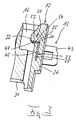
- the metallic holding element 13, 14 is made in one piece from one Formed sheet, i.e. punched and bent accordingly.
- the Holding element 13, 14 has a main region 45, which of a slightly wider head 46 is covered, and one perpendicular (i.e. by 90 °) to the large area of the Main area 45 and angled around its narrow edge Locking tab 47, which is at an axial distance from the head 46 is provided.
- One at the main area 45 subsequent foot area 48 is in the final state in a Fastening tab 49 and a fastening pin 50 branched out.
- the fastening pin 50 lies in the plane of the main area 45, while the fastening tab 49 perpendicular (i.e.
- the fastening tab 49 is in the main area 45 facing part with a slot, the Internal dimensions the outer dimensions of the mounting pin 50 corresponds, since the fastening pin 50 from the Fastening tab 49 is released or punched out.
- the mounting pin 50 in the width direction of the Main area 45 is centered on this and has on his free end inclined surfaces 51.
- the fastening pin 50 is much shorter than the mounting bracket 49.
- Figure 1 shows in solid lines the final state of Holding element 13, 14 as it is when the holding element 13, 14 is located in the plastic housing 12.
- the fastening tab 49 is located from the top still in the plane of the main area 45 and thus in the plane of the mounting pin 50, as shown in Figure 1 using the Holding element 13 is indicated dotted.
- 32 are the longitudinal slot 33 of the Side wall 26, 27 and the protruding into the top wall 28 Cross slot 34 formed accordingly.
- the Locking tab 47 with its front 17 facing surface 52 on a side wall 26 or 27 molded nose 22, 23 past by their rear surface 20 slides along, and lies exactly behind the nose 22, 23, if the head 46 on said shoulder in the longitudinal slot 33 lies on.
- the holding element 13, 14 is thus in the housing 12 fixed or immobile.
- the foot region 48 projects over the underside of the housing base 29, which has a longitudinal groove 24 is provided.
- the foot area 48 the fastening tab 49 in that shown in Figure 1 Position bent outwards by 90 °, being in the longitudinal groove 24 is recorded and the side wall 26 or 27 protrudes like this is particularly evident from Figure 2.
- the mounting pin 50 in a not shown corresponding recess in the circuit board 15 is pressed or is plugged in and soldered, lies the Mounting tab 49 on a surface area of the Printed circuit board 15, preferably a solder connection will be produced.
- the plastic housing 12 is over the holding elements 13 and 14 on the printed circuit board 15 connected immovably and mechanically stressable.
- the cable connector 11 has at the front end of its housing 61 accommodating a contact arrangement 62, in that a cable, not shown, is inserted Plug component 64, the active contacts with the plug-side connection ends 39 of the connector 10 are connectable.
- Plug component 64 has the plug component 64 on both narrow side surfaces elastic or held elastic Locking tongues 67, in the locking recesses 68 the Locking tabs 47 of the holding elements 13, 14 and the lugs 22, 23 engage in the plastic housing 12.
- For Unlocking can locking tabs 67 of the cable connector 11 through handles 69 held laterally on the housing 61 to the inside are deflected so that the recesses 68 of the Noses 22, 23 and locking tabs 47 forming counter-catches come free.
Landscapes
- Coupling Device And Connection With Printed Circuit (AREA)
- Details Of Connecting Devices For Male And Female Coupling (AREA)
- Earth Drilling (AREA)
- Piezo-Electric Or Mechanical Vibrators, Or Delay Or Filter Circuits (AREA)
- Quick-Acting Or Multi-Walled Pipe Joints (AREA)
Applications Claiming Priority (2)
| Application Number | Priority Date | Filing Date | Title |
|---|---|---|---|
| DE29613694U | 1996-08-08 | ||
| DE29613694U DE29613694U1 (de) | 1996-08-08 | 1996-08-08 | Steckverbinder |
Publications (1)
| Publication Number | Publication Date |
|---|---|
| EP0828320A1 true EP0828320A1 (fr) | 1998-03-11 |
Family
ID=8027544
Family Applications (1)
| Application Number | Title | Priority Date | Filing Date |
|---|---|---|---|
| EP97109524A Withdrawn EP0828320A1 (fr) | 1996-08-08 | 1997-06-12 | Connecteur |
Country Status (4)
| Country | Link |
|---|---|
| US (1) | US6030249A (fr) |
| EP (1) | EP0828320A1 (fr) |
| JP (1) | JPH1079280A (fr) |
| DE (1) | DE29613694U1 (fr) |
Cited By (2)
| Publication number | Priority date | Publication date | Assignee | Title |
|---|---|---|---|---|
| US6307934B1 (en) | 1999-06-03 | 2001-10-23 | Telefonaktiebolaget Lm Ericsson (Publ) | Multiconnector for mobile telephones |
| EP0991141A3 (fr) * | 1998-10-01 | 2002-02-13 | Hirose Electric Co., Ltd. | Connecteur de montage en surface |
Families Citing this family (10)
| Publication number | Priority date | Publication date | Assignee | Title |
|---|---|---|---|---|
| US6398577B1 (en) | 2000-10-04 | 2002-06-04 | Molex Incorporated | Latching/unlatching system for electrical connectors |
| JP2002124329A (ja) * | 2000-10-13 | 2002-04-26 | Auto Network Gijutsu Kenkyusho:Kk | 基板実装型コネクタ |
| JP4007970B2 (ja) * | 2004-03-30 | 2007-11-14 | 日本航空電子工業株式会社 | コネクタ固定部材とそれを用いたコネクタ |
| JP4262708B2 (ja) * | 2005-09-26 | 2009-05-13 | 住友電装株式会社 | 基板用コネクタ |
| US8657632B2 (en) * | 2011-12-07 | 2014-02-25 | Cheng Uei Precision Industry Co., Ltd. | I/O connector |
| JP6143874B2 (ja) | 2012-11-06 | 2017-06-07 | サーバー テクノロジー インコーポレイテッド | 高密度コンセント電力分配ユニット |
| US11296467B2 (en) * | 2012-11-06 | 2022-04-05 | Server Technology, Inc. | High outlet density power distribution unit |
| JP6148489B2 (ja) | 2013-02-13 | 2017-06-14 | 矢崎総業株式会社 | コネクタのペグ圧入構造 |
| DE102013102823A1 (de) * | 2013-03-19 | 2014-09-25 | Phoenix Contact Gmbh & Co. Kg | Ladestecker mit Verstärkungselement |
| USD809461S1 (en) * | 2013-11-06 | 2018-02-06 | Server Technology, Inc. | Outlet bank |
Citations (4)
| Publication number | Priority date | Publication date | Assignee | Title |
|---|---|---|---|---|
| WO1993002489A1 (fr) * | 1991-07-16 | 1993-02-04 | E.I. Du Pont De Nemours And Company | Systeme de fixation pour un boitier de connecteur |
| US5232379A (en) * | 1992-02-28 | 1993-08-03 | Foxconn International, Inc. | Connector with mounting means for SMT |
| EP0691712A1 (fr) * | 1994-07-04 | 1996-01-10 | Framatome Connectors International | Dispositif d'accouplement d'une paire de modules et son application à des connecteurs électriques complémentaires |
| WO1996007221A1 (fr) * | 1994-08-31 | 1996-03-07 | The Whitaker Corporation | Fixation et element de montage ameliores destines a un raccord electrique monte sur une surface |
Family Cites Families (19)
| Publication number | Priority date | Publication date | Assignee | Title |
|---|---|---|---|---|
| JPH0322865Y2 (fr) * | 1985-04-04 | 1991-05-17 | ||
| DE3538457C2 (de) * | 1985-10-29 | 1996-02-08 | Siemens Ag | Steckverbinder |
| DE3603250A1 (de) * | 1986-02-03 | 1987-08-06 | Allied Corp | Steckverbinder, isolierkoerper dafuer und verfahren zur befestigung des steckverbinders an einer leiterplatte |
| US4826442A (en) * | 1986-12-19 | 1989-05-02 | Amp Incorporated | Solderable connector retention feature |
| DE3734607C1 (en) * | 1987-10-13 | 1988-12-01 | Harting Elektronik Gmbh | Device for mounting plug connectors on printed circuit boards |
| DE8804956U1 (de) * | 1988-04-15 | 1988-06-09 | Harting Elektronik Gmbh, 4992 Espelkamp | Steckverbinder zur Befestigung an Leiterplatten |
| US4878858A (en) * | 1988-12-13 | 1989-11-07 | Molex Incorporated | Low profile shielded jack |
| US5021002A (en) * | 1989-12-20 | 1991-06-04 | Burndy Corporation | Snap-lock electrical connector with quick release |
| DE9000704U1 (de) * | 1990-01-23 | 1991-03-28 | Siemens Nixdorf Informationssysteme AG, 4790 Paderborn | Verriegelbare Flachsteckerkupplung |
| GB2244181B (en) * | 1990-04-13 | 1994-12-21 | Oki Electric Cable | Double lock male/female type connector |
| DE9004483U1 (de) * | 1990-04-19 | 1991-03-21 | Siemens Nixdorf Informationssysteme AG, 4790 Paderborn | Steckerkupplung |
| US5234357A (en) * | 1990-07-04 | 1993-08-10 | Hirose Electric Co., Ltd. | Lock mechanism for electrical connector |
| US5340329A (en) * | 1992-02-28 | 1994-08-23 | Honda Tsushin Kogyo Kabushiki Kaisha | Connector combination |
| US5259789A (en) * | 1993-02-23 | 1993-11-09 | Molex Incorporated | Retention system for circuit board mounted electrical connector |
| US5334049A (en) * | 1993-05-13 | 1994-08-02 | Molex Incorporated | Hold-down clip for board mounted electrical connector and method of use |
| US5354214A (en) * | 1993-07-23 | 1994-10-11 | Molex Incorporated | Printed circuit board electrical connector with mounting latch clip |
| US5468154A (en) * | 1993-12-15 | 1995-11-21 | Burndy Corporation | Multi-piece housing card edge connector with mounting arms |
| US5454729A (en) * | 1994-03-07 | 1995-10-03 | Wen-Te; Chuang | Electric plug and socket connecting mechanism |
| DE19500102C2 (de) * | 1995-01-04 | 1999-09-30 | Itt Cannon Gmbh | Verriegelungsvorrichtung für einen Steckverbinder |
-
1996
- 1996-08-08 DE DE29613694U patent/DE29613694U1/de not_active Expired - Lifetime
-
1997
- 1997-06-12 EP EP97109524A patent/EP0828320A1/fr not_active Withdrawn
- 1997-08-05 JP JP9210595A patent/JPH1079280A/ja active Pending
- 1997-08-07 US US08/908,671 patent/US6030249A/en not_active Expired - Lifetime
Patent Citations (4)
| Publication number | Priority date | Publication date | Assignee | Title |
|---|---|---|---|---|
| WO1993002489A1 (fr) * | 1991-07-16 | 1993-02-04 | E.I. Du Pont De Nemours And Company | Systeme de fixation pour un boitier de connecteur |
| US5232379A (en) * | 1992-02-28 | 1993-08-03 | Foxconn International, Inc. | Connector with mounting means for SMT |
| EP0691712A1 (fr) * | 1994-07-04 | 1996-01-10 | Framatome Connectors International | Dispositif d'accouplement d'une paire de modules et son application à des connecteurs électriques complémentaires |
| WO1996007221A1 (fr) * | 1994-08-31 | 1996-03-07 | The Whitaker Corporation | Fixation et element de montage ameliores destines a un raccord electrique monte sur une surface |
Cited By (2)
| Publication number | Priority date | Publication date | Assignee | Title |
|---|---|---|---|---|
| EP0991141A3 (fr) * | 1998-10-01 | 2002-02-13 | Hirose Electric Co., Ltd. | Connecteur de montage en surface |
| US6307934B1 (en) | 1999-06-03 | 2001-10-23 | Telefonaktiebolaget Lm Ericsson (Publ) | Multiconnector for mobile telephones |
Also Published As
| Publication number | Publication date |
|---|---|
| DE29613694U1 (de) | 1997-12-18 |
| US6030249A (en) | 2000-02-29 |
| JPH1079280A (ja) | 1998-03-24 |
Similar Documents
| Publication | Publication Date | Title |
|---|---|---|
| DE68921117T2 (de) | Randverbinder für Leiterplatten und Anschlusselement dafür. | |
| DE2054201C3 (de) | Zur Verwendung in einem elektrischen Steckverbinder bestimmtes elektrisches Kontaktelement | |
| DE2130855C2 (de) | Steckverbindungsvorrichtung für eine Leiterplatte | |
| DE69306463T2 (de) | Elektrischer Flachbauverbinder | |
| DE69129580T2 (de) | Abgeschirmter elektrischer Verbinder für gedruckte Schaltungsplatten | |
| DE102009022094B4 (de) | Stapelverbinder | |
| DE69410934T2 (de) | Elektrischer Verbinder | |
| DE69409469T2 (de) | Leiterplattenverbinder mit verbessertem Verriegelungs- und Auswerfmechanismus | |
| DE69016871T2 (de) | Elektrischer Steckverbinder. | |
| DE69230497T2 (de) | Befestigungsvorrichtung für ein verbindergehäuse | |
| DE69502958T2 (de) | Verriegelungs- und montageelement fuer einen oberflaechenmontierten elektrischen verbinder | |
| DE69022657T2 (de) | Leiterplattenoberflächen montierbarer elektrischer Verbinder. | |
| DE69112710T2 (de) | Elektrischer Steckverbinder von Leiterplatte zu Leiterplatte mit Stiften und Buchsen von verringertem Teilungsmass. | |
| DE69019804T2 (de) | Steckdose für mehrpoligen Verbinder. | |
| DE2204924A1 (de) | Elektrische Verbinderanordnung | |
| DE8800759U1 (de) | Elektrischer Verbinder mit beweglichem Führungselement | |
| DE2446081A1 (de) | Elektrische verbinderanordnung | |
| DE9115318U1 (de) | Elektrischer Verbinder mit reduzierter Einführkraft | |
| DE2406125A1 (de) | Buchsenkontakt | |
| DE2212807C2 (de) | Elektrische Verbinderanordnung | |
| DE10119695B4 (de) | Steckverbinder für elektronische Bauelemente | |
| DE69306280T2 (de) | Elektrischer Steckverbinder | |
| DE19621614C1 (de) | Steckverbinder | |
| DE69410575T2 (de) | Elektrische Verbinderanordnung zum Montieren auf gedruckte Leiterplatten | |
| DE69602020T2 (de) | Zusammenbau einer elektrischenanschlussbuchse und federkontakt dafür |
Legal Events
| Date | Code | Title | Description |
|---|---|---|---|
| PUAI | Public reference made under article 153(3) epc to a published international application that has entered the european phase |
Free format text: ORIGINAL CODE: 0009012 |
|
| AK | Designated contracting states |
Kind code of ref document: A1 Designated state(s): DE FI FR GB IT SE |
|
| 17P | Request for examination filed |
Effective date: 19980909 |
|
| AKX | Designation fees paid |
Free format text: DE FI FR GB IT SE |
|
| RBV | Designated contracting states (corrected) |
Designated state(s): DE FI FR GB IT SE |
|
| 17Q | First examination report despatched |
Effective date: 20041012 |
|
| STAA | Information on the status of an ep patent application or granted ep patent |
Free format text: STATUS: THE APPLICATION IS DEEMED TO BE WITHDRAWN |
|
| 18D | Application deemed to be withdrawn |
Effective date: 20050222 |