EP0828565B1 - Pistolet pulverisateur de poudre a distributeur rotatif - Google Patents
Pistolet pulverisateur de poudre a distributeur rotatif Download PDFInfo
- Publication number
- EP0828565B1 EP0828565B1 EP96917815A EP96917815A EP0828565B1 EP 0828565 B1 EP0828565 B1 EP 0828565B1 EP 96917815 A EP96917815 A EP 96917815A EP 96917815 A EP96917815 A EP 96917815A EP 0828565 B1 EP0828565 B1 EP 0828565B1
- Authority
- EP
- European Patent Office
- Prior art keywords
- powder
- spindle
- distributor
- spray gun
- chamber
- Prior art date
- Legal status (The legal status is an assumption and is not a legal conclusion. Google has not performed a legal analysis and makes no representation as to the accuracy of the status listed.)
- Expired - Lifetime
Links
Images



Classifications
-
- B—PERFORMING OPERATIONS; TRANSPORTING
- B05—SPRAYING OR ATOMISING IN GENERAL; APPLYING FLUENT MATERIALS TO SURFACES, IN GENERAL
- B05B—SPRAYING APPARATUS; ATOMISING APPARATUS; NOZZLES
- B05B3/00—Spraying or sprinkling apparatus with moving outlet elements or moving deflecting elements
- B05B3/02—Spraying or sprinkling apparatus with moving outlet elements or moving deflecting elements with rotating elements
- B05B3/10—Spraying or sprinkling apparatus with moving outlet elements or moving deflecting elements with rotating elements discharging over substantially the whole periphery of the rotating member
- B05B3/1064—Spraying or sprinkling apparatus with moving outlet elements or moving deflecting elements with rotating elements discharging over substantially the whole periphery of the rotating member the liquid or other fluent material to be sprayed being axially supplied to the rotating member through a hollow rotating shaft
-
- B—PERFORMING OPERATIONS; TRANSPORTING
- B05—SPRAYING OR ATOMISING IN GENERAL; APPLYING FLUENT MATERIALS TO SURFACES, IN GENERAL
- B05B—SPRAYING APPARATUS; ATOMISING APPARATUS; NOZZLES
- B05B5/00—Electrostatic spraying apparatus; Spraying apparatus with means for charging the spray electrically; Apparatus for spraying liquids or other fluent materials by other electric means
- B05B5/025—Discharge apparatus, e.g. electrostatic spray guns
- B05B5/04—Discharge apparatus, e.g. electrostatic spray guns characterised by having rotary outlet or deflecting elements, i.e. spraying being also effected by centrifugal forces
-
- B—PERFORMING OPERATIONS; TRANSPORTING
- B05—SPRAYING OR ATOMISING IN GENERAL; APPLYING FLUENT MATERIALS TO SURFACES, IN GENERAL
- B05B—SPRAYING APPARATUS; ATOMISING APPARATUS; NOZZLES
- B05B5/00—Electrostatic spraying apparatus; Spraying apparatus with means for charging the spray electrically; Apparatus for spraying liquids or other fluent materials by other electric means
- B05B5/025—Discharge apparatus, e.g. electrostatic spray guns
- B05B5/04—Discharge apparatus, e.g. electrostatic spray guns characterised by having rotary outlet or deflecting elements, i.e. spraying being also effected by centrifugal forces
- B05B5/0418—Discharge apparatus, e.g. electrostatic spray guns characterised by having rotary outlet or deflecting elements, i.e. spraying being also effected by centrifugal forces designed for spraying particulate material
-
- B—PERFORMING OPERATIONS; TRANSPORTING
- B05—SPRAYING OR ATOMISING IN GENERAL; APPLYING FLUENT MATERIALS TO SURFACES, IN GENERAL
- B05B—SPRAYING APPARATUS; ATOMISING APPARATUS; NOZZLES
- B05B5/00—Electrostatic spraying apparatus; Spraying apparatus with means for charging the spray electrically; Apparatus for spraying liquids or other fluent materials by other electric means
- B05B5/025—Discharge apparatus, e.g. electrostatic spray guns
- B05B5/04—Discharge apparatus, e.g. electrostatic spray guns characterised by having rotary outlet or deflecting elements, i.e. spraying being also effected by centrifugal forces
- B05B5/0422—Discharge apparatus, e.g. electrostatic spray guns characterised by having rotary outlet or deflecting elements, i.e. spraying being also effected by centrifugal forces comprising means for controlling speed of rotation
-
- B—PERFORMING OPERATIONS; TRANSPORTING
- B05—SPRAYING OR ATOMISING IN GENERAL; APPLYING FLUENT MATERIALS TO SURFACES, IN GENERAL
- B05B—SPRAYING APPARATUS; ATOMISING APPARATUS; NOZZLES
- B05B3/00—Spraying or sprinkling apparatus with moving outlet elements or moving deflecting elements
- B05B3/02—Spraying or sprinkling apparatus with moving outlet elements or moving deflecting elements with rotating elements
- B05B3/10—Spraying or sprinkling apparatus with moving outlet elements or moving deflecting elements with rotating elements discharging over substantially the whole periphery of the rotating member
- B05B3/1092—Means for supplying shaping gas
-
- B—PERFORMING OPERATIONS; TRANSPORTING
- B05—SPRAYING OR ATOMISING IN GENERAL; APPLYING FLUENT MATERIALS TO SURFACES, IN GENERAL
- B05B—SPRAYING APPARATUS; ATOMISING APPARATUS; NOZZLES
- B05B5/00—Electrostatic spraying apparatus; Spraying apparatus with means for charging the spray electrically; Apparatus for spraying liquids or other fluent materials by other electric means
- B05B5/025—Discharge apparatus, e.g. electrostatic spray guns
- B05B5/04—Discharge apparatus, e.g. electrostatic spray guns characterised by having rotary outlet or deflecting elements, i.e. spraying being also effected by centrifugal forces
- B05B5/0426—Means for supplying shaping gas
Definitions
- This invention relates to electrostatic powder spray guns, and more particularly to a gun having a rotating member at the powder outlet for distributing the powder in a uniform spray pattern.
- powder coating In electrostatic powder painting, dry paint particles are fluidized in a powder hopper and pumped through a hose to one or more spray guns which spray the powder onto a product to be coated.
- the spray guns impart a charge to the powder particles, typically with a high voltage charging electrode.
- the powder particles When the powder particles are sprayed from the front of the gun, they are electrostatically attracted to the product to be painted which is generally electrically grounded and which may be suspended from an overhead conveyer or otherwise carried in a spray booth. Once these charged powder particles are deposited onto the product, they adhere there by electrostatic attraction until they are conveyed into an oven where they are melted to flow together to form a continuous coating on the product.
- Powder coating generally provides a tough and durable finish such as would be found on many appliances, garden furniture, lawn mowers, and other products.
- powder spray guns with rotating distributors at the powder outlet provide improved spray patterns and other benefits.
- the designs of many powder spray guns of this type have been based upon similar liquid spray guns that have rotating atomizers at the fluid outlet. Examples of liquid spray guns of this type are shown in U.S. Patents Nos. 4,887,770 and 5,346,139.
- the rotating distributors in liquid spray guns rotate at very high speeds, with a typical speed of such spray guns being around 20,000-50,000 rpm. These high speeds are necessary because the distributors must atomize the liquid coating material, and the atomization is best achieved at these speeds.
- the guns are not generally designed to be capable of slower speeds, because slower speeds would not effectively atomize the liquid and because the rotary distributors are driven by air turbine motors which cannot operate effectively at slower speeds.
- U.S. Patent 5353995 discloses a sprayer having a turbine.
- the output shaft of the turbine is continuously cleaned by air escaping from a chamber formed in the sprayer body via an annular clearance between the shaft and a cap.
- the present invention provides a spray gun for coating material comprising a housing having a body, a chamber within the body, the chamber connected to an air supply to pressurise the chamber, a spindle mounted for rotation within the chamber, the spindle having a central passageway, a non-rotating flow tube through which powder flows, a gap being formed between the non-rotating flow tube and the rotatable spindle, the gap communicating with the chamber, a distributor attached for rotation with the spindle and receiving powder to be sprayed from the gun, and a drive mechanism located within the housing and connected to rotate the spindle and the distributor (39), characterised in that the spindle central passageway forms a portion of the powder flow path, powder flowing from the flow tube into the passageway and being received by the distributor from the passageway, and in that pressurised air from the chamber escapes through the gap to provide a rotary seal between the tube and the spindle.
- the problem of powder accumulations in the gun is avoided by providing a pressurized chamber around a rotating spindle which has a central passageway forming part of the powder flow path.
- the chamber around the spindle is connected to a supply of pressurized air, and the chamber is pressurized slightly above the pressure of the fluidized powder flow through the gun.
- Air in the pressurized chamber can escape from the chamber around the spindle and around its associated bearings, and when the air escapes, it effectively sweeps powder from the periphery of the spindle, keeping the areas around the spindle and the bearings clean of powder.
- the air escapes through an annular gap formed between the stationary powder supply tube and the rotating spindle, providing an effective rotary seal without the necessity of additional components.
- the rotary seal provided by this invention avoids the use of conventional seals, such as lip seals or O-rings, and avoids the problems of friction created between the rotating spindle and the stationary tube which would otherwise accelerate wear and tend to cause increased powder fusing.
- the spray gun is capable of operating at slower speeds than prior art spray guns, and thus the problems associated with powder fusing are reduced or eliminated. In addition, by operating at slower speeds, the spray gun increases bearing life and otherwise reduces wear on moving parts within the gun.
- the spray gun provides a rotating distributor which rotates at speeds which are much slower than the speeds of the prior art spray guns.
- Turbines such as those used in prior art spray guns, can operate effectively only as slow as about 2.500 rpm. At slower speeds they will not operate at a consistent or even speed, or may not operate at all.
- the present gun avoids the use of a turbine to turn the distributor, so that it can achieve much slower speeds effectively.
- the distributor in the gun can rotate evenly and consistently at speeds of from 0 to 2.500 rpm.
- the gun preferably uses a pneumatic or air motor or an electric motor.
- Other suitable motors can also be effectively used.
- an air motor or an electric motor is relatively inexpensive.
- an air motor or electric motor or other comparable motor can be easily replaced if it fails or becomes worn.
- the motor used in the spray gun is preferably radially offset from the central axis of the gun, so that the central axis can be devoted to the powder flow path.
- the overall design of the spray gun of the present invention is thus simpler, relatively inexpensive to manufacture and maintain, and easier to operate.
- the parts are arranged in a modular design, making it easy to replace parts.
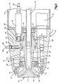
- FIG. 1 is a side sectional view of the spray gun of the present invention.
- FIG. 2 is a detailed view of a portion of FIG. 1 .
- FIG. 3 is an end sectional view of the spray gun taken along line 3 ⁇ 3 of FIG. 1.
- FIG. 4 is an end elevational view of the spray gun taken along line 4 ⁇ 4 of FIG. 1.
- FIG. 5 is 2 side sectional view of the spray gun similar to FIG. 2 showing a different cross section taken along line 5 ⁇ 5 of FIG. 4 .
- FIG. 6 is a side sectional view similar to a portion of FIG. 1 but taken alone a different sectional line showing other components in the rear end panel.
- a powder spray gun 10 comprising a housing including a body 11 .
- the body 11 is formed of a nonconductive plastic material and has a central chamber 12 .
- the forward end of the chamber 12 is enclosed by a from end cap 13 which is also formed of a nonconductive plastic material and which is threadedly attached to the front of the body 11 .
- a tubular housing sleeve 14 having a hollow interior 15 is attached to the body 11 and extends rearwardly from the body.
- a rear body member 16 is mounted on the rear of the sleeve 14, and a rear end panel member 17 is removably mounted on the rear of the body member 16 by a pair of clamping assemblies 18 .
- the rear end panel member 17 can be mounted on the rear of the body member 16 by a threaded connection or by other means.
- a drive mechanism comprising a motor 22 is mounted in the body 11 and extends rearwardly from the body in the sleeve interior 15.
- the motor 22 is preferably a pneumatic or air motor. but may also be a small electric motor. Although any suitable air motor may be used, the preferred air motor is a model MMR0700N available from Micro Motors, Inc.
- the air motor 22 is connected to an air supply line 23 which extends through the sleeve interior 15 and is connected to a connection 24 at the rear end panel 17 (FIG. 4 )
- a suitable regulated air supply is connected to the connection 24 to operate the air motor 22 .
- the air motor 22 is also connected to an air exhaust line 25 which extends through the sleeve interior 15 and is connected to a connection 26 at the rear end panel 17.
- the air motor 22 has an output shaft 27 , and the motor turns the shaft at a various speeds depending upon the pressure of the regulated air supply.
- a typical shaft rotational speed would be between 0 and 7,000 rpm.
- a gear 28 which is mounted on the shaft 27 engages another gear 29 which attached by means of screws 30 to a spindle 31 rotatably mounted in the chamber.
- the gears 28 and 29 produce a suitable gear reduction, e.g. , 3 to 1, which decreases the rotational speed of the spindle 31 and increases the torque produced by the air motor 22.
- the spindle 31 rotates within the chamber 12 in the body 11 , and is supported on front and rear sleeve bearings 36 and 37.
- a bearing retainer 38 which is threadedly mounted on the front of the body 11 and which covers the chamber 12 , is located between the front sleeve bearing 36 and the front end cap 13 and holds the front sleeve bearing 36 in place.
- a two-piece rotatable powder distributor or nozzle assembly 39 is mounted on the front end of the spindle 31.
- the nozzle assembly 39 comprises a inner nozzle member 40 and an outer nozzle member 41 .
- the inner nozzle member 40 is threadedly connected to the front end of the spindle 31 to rotate with the spindle.
- the outer nozzle member 41 is spaced from the inner nozzle member 40 with a gap 42 therebetween for the passage of powder, and the outer nozzle member is attached to the inner nozzle member 40 by means of a plurality, of screws 43 (FIG. 5) which extend across the gap 42 , so that the outer nozzle member rotates with the inner nozzle member.
- vanes may be located within the gap on one of the nozzle members to achieve the desired spray pattern for the powder as the nozzle members rotate or to enhance the ability of the nozzle assembly 39 to deliver powder.
- the spindle 31 has a central interior passageway 48 through which powder flows.
- the interior passageway 48 communicates with the gap 42 between the nozzle members 40 and 41 , so that powder flowing through the passageway in the spindle 31 flows directly into the gap between the nozzle members.
- Powder enters the passageway 48 in the rotating spindle 31 from 2 nonrotating tube 49 which exiends into the rear of the spindle.
- the tube 49 extends rearwardly from the spindle 31 through the center of the sleeve interior 15 and to the rear end panel 17 where it is connected to a powder supply hose 50 .
- the supply hose 50 can be connected to a conventional powder supply system comprising a fluidized powder hopper, a pump and a control module.
- the forward end of the tube 49 extends partially into the spindle passageway 48 , and an annular gap 51 is thus formed between the stationary tube 49 and the rotating spindle 31 .
- the powder which flows through the spindle could enter the bearings and impede the rotation of the spindle.
- positive air pressure is maintained within the chamber 12 .
- the positive air pressure is achieved by connecting the chamber 12 to an air line 52 (FIG. 3 ) which extends through the sleeve interior 15 to a connection 53 (FIG. 4 ) on the rear end panel 17 .
- the air pressure in the chamber 12 is maintained at around 15 - 25 psi. Air can escape from the chamber 12 between the front sleeve bearing 36 and the spindle 31 and between the rear sleeve bearing 37 and the spindle.
- the air escapes from the rear bearing 37 it is channeled through the annular opening 51 , and eventually it enters the passageway 48 in the spindle and becomes part of the powder flow.
- the escape of air from the pressurized chamber 12 thus sweeps powder accumulations from the path through which the air flows, and the surfaces around the sleeve bearings 36 and 37 and the spindle 31 are thus maintained relatively free of powder.
- the flow of air through the annular opening 51 also prevents powder from flowing from the powder flow path of the passageway 48 into areas around the spindle 31 and the bearings 36 and 37 . This escape of air effectively creates an air seal at the annular gap 51 which is formed where the stationary tube 49 engages the rotating spindle 31 .
- a spindle locking assembly 58 is provided in the body 11 .
- the spindle locking assembly 58 comprises a locking member 59 (FIG. 2 ) capable of moving radially within a bore in the body 11 .
- One end 60 of the locking member 59 extends from the exterior of the body 11 and the other end 61 is capable of projecting into one of several shallow holes 62 formed around the exterior of the spindle 31.
- the locking member 59 is urged radially outwardly by a spring 63 and is held inwardly by a conventional retaining clip 64 .
- the present invention avoids the use of special tools which were necessary with prior art spray guns.
- the connection 69 is connected to a high-voltage multiplier 70 mounted in the sleeve interior 15 between the body 11 and the rear end panel 17 .
- the multiplier 70 can be the same as or similar to those used in other electrostatic powder spray guns.
- the multiplier 70 is connected to a limiting resisior 71 located within the body 11 , and the resistor 71 is connected to a conductive O-ring 72 located in a groove between the body 11 and the front end cap 13 .
- a plurality of electrodes 73 are mounted in the front of the end cap 13 and extend from the front of the gun around the outer radial periphery of the nozzle assembly 39 .
- each electrode 73 is used, each 180° with respect to each other.
- the tip of each electrode 73 extends from the front surface of the end cap 13 and charges the powder as it exits from the gap 42 formed in the nozzle assembly 39 .
- the rotational speed of the spindle 31 is varied by changing the pressure of the air supply to the air motor 22 .
- the same air pressure to the air motor 22 will not always produce the same spindle speed due to changes in powder flow rates and specific gravity of the powder, due to frictional drag of the powder which varies according to the powder flow rate. Therefore, it is usually necessary to measure directly the rotational speed of the spindle 31 .
- Spindle speed is detected by a speed detector comprising a sensor 78 (FIG. 3 ) located within the sleeve interior 15 .
- a pair of fiber optic lines 79 extend from the sensor 78 through a bore 80 in the body 11 . The ends of the fiber optic lines 79 are aimed at the rotating gear 29 .
- the gear 29 includes the pair of screws 30 which are of contrasting appearance with the gear.
- the gear 29 is made of a material which is dark in color or light absorbent, the screws 30 would be made of a light or bright or shiny material.
- One of the fiber optic lines 79 carries light to illuminate the screws 30 on the gear 29 .
- the other of the lines 79 carries light reflected from the screws 30 back to the sensor 78 .
- As the gear 29 rotates light reflected by the screws 30 and carried to the sensor 78 by the fiber optic lines 79 is used to detect the presence of the screws 30 and thereby detect each rotation of the gear 29.
- the speed of rotation of the gear 29 matches the speed of rotation of the spindle 31 , so the spindle speed is determined thereby by the sensor 78 .
- the sensor 78 can be connected to a suitable output device or control device through an electrical connection 81 located on the rear end panel 17 .
- the speed detector can be connected to the air supply to the air motor 22 in accordance with known techniques so that the speed of the spindle can be controlled.
- the rear end panel 17 may also be provided with two or more additional air connections 86 and 87 . These connections 86 and 87 may be used for additional capabilities, such as, for air supplied to the portals on the front of the end cap 13 to shape the flow of powder existing from the nozzle assembly, or for air supplied to the electrodes 73 to cool or shape the air around the electrodes, or for air used to sweep accumulated powder. If it is desired to supply air to the electrodes 73, for example, another air hose 88 (FIG. 5 ) would be provided in the sleeve interior 15 and would be connected to an air passageway 89 extending through the body 11 . A suitable vent or port (not shown) would then be provided in the front end cap 13 so that air could exit around the electrode 73 .
Landscapes
- Nozzles (AREA)
- Electrostatic Spraying Apparatus (AREA)
Abstract
Claims (7)
- Pistolet pulvérisateur (10) pour enduire un matériau comprenant un boítier ayant un corps (11), une chambre (12) à l'intérieur du corps (11), la chambre (12) reliée à une alimentation d'air pour mettre sous pression la chambre, une broche (31) montée pour tourner avec la chambre (12), la broche (31) ayant un passage central (48), un tube d'écoulement non rotatif (49) à travers lequel la poudre passe, un intervalle (51) étant formé entre le tube d'écoulement non rotatif (49) et la broche (31) rotative, l'intervalle (51) communiquant avec la chambre (12), un distributeur (39) fixé pour tourner avec la broche (31) et recevant la poudre devant être pulvérisée par le pistolet, et un mécanisme d'entraínement (22) situé à l'intérieur du boítier et relié pour faire tourner la broche (31) et le distributeur (39), caractérisé en ce que le passage central (48) de la broche forme une partie du chemin d'écoulement de la poudre, la poudre passant du tube d'écoulement (49) au passage (48) et étant reçue par le distributeur (39) depuis le passage (48), et en ce que l'air pressurisé provenant de la chambre (12) s'échappe via l'intervalle (51) pour créer un joint rotatif entre le tube (49) et la broche (31).
- Pistolet pulvérisateur selon la revendication 1, dans lequel la broche (31) et le distributeur (39) tournent autour de l'axe longitudinal central du corps (11), et dans lequel le mécanisme d'entraínement (22) est situé le long d'un axe radialement espacé de l'axe longitudinal du corps.
- Pistolet pulvérisateur selon la revendication 1 ou la revendication 2 dans lequel le chemin d'écoulement de la poudre passe à travers le corps (11) jusqu'à une sortie de poudre, le distributeur (39) de poudre rotatif étant situé à la sortie de poudre.
- Pistolet pulvérisateur selon l'une quelconque des précédentes revendications comprenant en plus une pluralité d'électrodes discrètes (73) montées pour s'étendre depuis l'extérieur du boítier, les électrodes (73) situées radialement au-delà du diamètre extérieur du distributeur (39).
- Pistolet pulvérisateur selon la revendication 4, comprenant en plus une alimentation électrique interne située à l'intérieur du boítier et reliée aux électrodes (73).
- Pistolet pulvérisateur selon la revendication 4, comprenant en plus un anneau conducteur (72) situé à l'intérieur du boítier autour du chemin d'écoulement, l'anneau (72) reliant les électrodes (73) à une alimentation électrique.
- Pistolet pulvérisateur selon l'une quelconque des précédentes revendications, caractérisé en ce que le mécanisme d'entraínement est un moteur (22) capable de faire tourner de manière régulière le distributeur (39) à des vitesses inférieures à 2500 tr/min.
Applications Claiming Priority (3)
| Application Number | Priority Date | Filing Date | Title |
|---|---|---|---|
| US44478595A | 1995-05-19 | 1995-05-19 | |
| US444785 | 1995-05-19 | ||
| PCT/US1996/007239 WO1996036438A1 (fr) | 1995-05-19 | 1996-05-20 | Pistolet pulverisateur de poudre a distributeur rotatif |
Publications (3)
| Publication Number | Publication Date |
|---|---|
| EP0828565A1 EP0828565A1 (fr) | 1998-03-18 |
| EP0828565A4 EP0828565A4 (fr) | 1998-09-02 |
| EP0828565B1 true EP0828565B1 (fr) | 2002-09-18 |
Family
ID=23766348
Family Applications (1)
| Application Number | Title | Priority Date | Filing Date |
|---|---|---|---|
| EP96917815A Expired - Lifetime EP0828565B1 (fr) | 1995-05-19 | 1996-05-20 | Pistolet pulverisateur de poudre a distributeur rotatif |
Country Status (6)
| Country | Link |
|---|---|
| US (1) | US5816508A (fr) |
| EP (1) | EP0828565B1 (fr) |
| JP (1) | JPH11505173A (fr) |
| AU (1) | AU6022996A (fr) |
| DE (1) | DE69623768T2 (fr) |
| WO (1) | WO1996036438A1 (fr) |
Cited By (1)
| Publication number | Priority date | Publication date | Assignee | Title |
|---|---|---|---|---|
| DE102005018403A1 (de) * | 2005-04-20 | 2006-11-09 | Kamat-Pumpen Gmbh & Co. Kg | Waschkopf zum Innenreinigen von Behältern, wie Tanks, Rohre oder dergleichen |
Families Citing this family (24)
| Publication number | Priority date | Publication date | Assignee | Title |
|---|---|---|---|---|
| US6105886A (en) * | 1995-05-19 | 2000-08-22 | Nordson Corporation | Powder spray gun with rotary distributor |
| US5947377A (en) * | 1997-07-11 | 1999-09-07 | Nordson Corporation | Electrostatic rotary atomizing spray device with improved atomizer cup |
| FR2776946B1 (fr) * | 1998-04-01 | 2000-05-26 | Sames Sa | Bol de pulverisation et projecteur rotatif electrostatique equipe d'un tel bol |
| US6758423B1 (en) | 1999-09-17 | 2004-07-06 | Nordson Corporation | Spray gun with data device and method of control |
| US20020088397A1 (en) * | 2000-05-03 | 2002-07-11 | Perkins Jeffrey A. | Coating system with centralized control panel and gun mapping |
| US6379465B1 (en) | 1999-09-17 | 2002-04-30 | Nordson Corporation | Coating system with centralized control panel and gun mapping |
| US6977013B2 (en) | 1999-09-17 | 2005-12-20 | Nordson Corporation | Powder coating system central controller |
| DE10053292C1 (de) * | 2000-10-27 | 2002-05-23 | Eisenmann Lacktechnik Kg | Hochrotationszerstäuber zur Aufbringung von Pulverlack |
| DE60141457D1 (de) * | 2000-12-20 | 2010-04-15 | Abb Kk | Beschichtungsvorrichtung mit einem rotationszerstäuberkopf |
| DE10115462A1 (de) * | 2001-03-29 | 2002-10-02 | Duerr Systems Gmbh | Rotationszerstäuber mit einer blockierbaren Welle |
| US7080794B2 (en) | 2001-03-29 | 2006-07-25 | Dürr Systems, Inc. | Rotary atomizer with blockable shaft |
| JP2005516771A (ja) * | 2002-02-12 | 2005-06-09 | ノードソン コーポレーション | 静電スプレーガンの内部電源用制御装置 |
| US7128277B2 (en) * | 2003-07-29 | 2006-10-31 | Illinois Tool Works Inc. | Powder bell with secondary charging electrode |
| US7793869B2 (en) * | 2003-08-18 | 2010-09-14 | Nordson Corporation | Particulate material applicator and pump |
| US20070104886A1 (en) * | 2005-11-10 | 2007-05-10 | General Electric Company | Electrostatic spray for coating aircraft engine components |
| US20050202270A1 (en) * | 2004-03-10 | 2005-09-15 | Skoog Andrew J. | Powder coating of gas turbine engine components |
| SE527890C2 (sv) * | 2004-05-18 | 2006-07-04 | Lind Finance & Dev Ab | Skyddande av spindelaxel |
| JP4971327B2 (ja) * | 2006-07-19 | 2012-07-11 | Abb株式会社 | 回転霧化頭型塗装機 |
| FR2915114B1 (fr) * | 2007-04-23 | 2010-09-10 | Sames Technologies | Organe de pulverisation,dispositif de projection comportant un tel organe et installation de projection comprenant un tel dispositif |
| DE102009013979A1 (de) | 2009-03-19 | 2010-09-23 | Dürr Systems GmbH | Elektrodenanordnung für einen elektrostatischen Zerstäuber |
| CN107321518B (zh) * | 2017-06-22 | 2018-12-25 | 张家港清研再制造产业研究院有限公司 | 一种内孔双丝电弧旋转喷涂设备 |
| CN110976153A (zh) * | 2019-09-20 | 2020-04-10 | 北京联合涂层技术有限公司 | 一种电弧喷枪旋转设备 |
| CN112896517B (zh) * | 2021-02-05 | 2023-02-07 | 海南天然橡胶产业集团股份有限公司 | 一种橡胶林无人机喷粉效果测试装置 |
| JP2026500829A (ja) * | 2023-01-05 | 2026-01-08 | エー・ビー・デブ・リミテッド | シャフトロック機構及び回転式噴霧器のためのシステム |
Family Cites Families (11)
| Publication number | Priority date | Publication date | Assignee | Title |
|---|---|---|---|---|
| US2922584A (en) * | 1956-11-19 | 1960-01-26 | Ford Motor Co | Dual spray painting |
| FR2412351A1 (fr) * | 1977-12-20 | 1979-07-20 | Air Ind | Projecteur electrostatique de peinture a bol ou a disque tournant avec un joint d'etancheite pneumatique |
| JPS58216751A (ja) * | 1982-06-11 | 1983-12-16 | Toshiyuki Kadowaki | 静電塗装方法 |
| US4589597A (en) * | 1983-10-03 | 1986-05-20 | Graco Inc. | Rotary atomizer spray painting device |
| US4936510A (en) * | 1986-06-26 | 1990-06-26 | The Devilbiss Company | Rotary automizer with air cap and retainer |
| US4936507A (en) * | 1986-06-26 | 1990-06-26 | The Devilbiss Company | Rotary atomizer with high voltage isolating speed measurement |
| ES2004334B3 (es) * | 1987-03-23 | 1992-01-16 | Behr Ind Gmbh & Co | Procedimiento para el recubrimiento electrostatico de pieza de trabajo |
| US4927081A (en) * | 1988-09-23 | 1990-05-22 | Graco Inc. | Rotary atomizer |
| US5100057A (en) * | 1990-03-30 | 1992-03-31 | Nordson Corporation | Rotary atomizer with onboard color changer and fluid pressure regulator |
| FR2692173B1 (fr) * | 1992-06-10 | 1994-09-02 | Sames Sa | Dispositif de projection électrostatique d'un produit de revêtement en poudre à tête d'ionisation tournante. |
| DE4335507A1 (de) * | 1993-10-19 | 1995-04-27 | Hestermann Gerhard | Pulversprühorgan |
-
1996
- 1996-05-20 EP EP96917815A patent/EP0828565B1/fr not_active Expired - Lifetime
- 1996-05-20 JP JP8535123A patent/JPH11505173A/ja active Pending
- 1996-05-20 WO PCT/US1996/007239 patent/WO1996036438A1/fr not_active Ceased
- 1996-05-20 AU AU60229/96A patent/AU6022996A/en not_active Abandoned
- 1996-05-20 DE DE69623768T patent/DE69623768T2/de not_active Expired - Fee Related
-
1997
- 1997-04-07 US US08/826,726 patent/US5816508A/en not_active Expired - Fee Related
Cited By (2)
| Publication number | Priority date | Publication date | Assignee | Title |
|---|---|---|---|---|
| DE102005018403A1 (de) * | 2005-04-20 | 2006-11-09 | Kamat-Pumpen Gmbh & Co. Kg | Waschkopf zum Innenreinigen von Behältern, wie Tanks, Rohre oder dergleichen |
| DE102005018403B4 (de) * | 2005-04-20 | 2007-05-10 | Kamat-Pumpen Gmbh & Co. Kg | Waschkopf zum Innenreinigen von Behältern, wie Tanks oder Rohren |
Also Published As
| Publication number | Publication date |
|---|---|
| EP0828565A4 (fr) | 1998-09-02 |
| US5816508A (en) | 1998-10-06 |
| EP0828565A1 (fr) | 1998-03-18 |
| WO1996036438A1 (fr) | 1996-11-21 |
| DE69623768D1 (de) | 2002-10-24 |
| JPH11505173A (ja) | 1999-05-18 |
| DE69623768T2 (de) | 2003-08-14 |
| AU6022996A (en) | 1996-11-29 |
Similar Documents
| Publication | Publication Date | Title |
|---|---|---|
| US5816508A (en) | Powder spray gun with rotary distributor | |
| US6105886A (en) | Powder spray gun with rotary distributor | |
| US4896834A (en) | Rotary atomizer apparatus | |
| US4684064A (en) | Centrifugal atomizer | |
| AU643192B2 (en) | Electrostatic rotary atomizing liquid spray coating apparatus | |
| US4643357A (en) | Rapidly cleanable atomizer | |
| US4927081A (en) | Rotary atomizer | |
| US5922131A (en) | Electrostatic powder spray coating apparatus with rotating spray orifice | |
| CA1165109A (fr) | Moteur d'atomiseur | |
| US5803372A (en) | Hand held rotary atomizer spray gun | |
| US20030164406A1 (en) | Sprayer device for spraying a liquid coating product | |
| KR100320344B1 (ko) | 회전무화헤드형 도장장치 | |
| US7721976B2 (en) | High speed rotating atomizer assembly | |
| KR970001789B1 (ko) | 정전 분무 도장장치 | |
| CA2367254C (fr) | Technique et systeme de pulverisation pour enduits liquides | |
| US6854665B1 (en) | System for spraying a powder coating product and sprayhead incorporated in it | |
| JPH0141496Y2 (fr) | ||
| GB2197224A (en) | Electrostatic spray gun | |
| JPH06134353A (ja) | 静電塗装装置 | |
| EP1066117B1 (fr) | Dispositif rotatif de transmission de matiere sous forme particulaire | |
| GB2278554A (en) | Rotary atomiser for a food flavouring system | |
| GB2193447A (en) | Electrostatic spray coating apparatus | |
| GB2250697A (en) | Rotary atomizer | |
| JPH04334565A (ja) | 回転霧化頭型静電塗装装置 | |
| JPS57102252A (en) | Rotary atomizer for electrostatic painting |
Legal Events
| Date | Code | Title | Description |
|---|---|---|---|
| PUAI | Public reference made under article 153(3) epc to a published international application that has entered the european phase |
Free format text: ORIGINAL CODE: 0009012 |
|
| 17P | Request for examination filed |
Effective date: 19971127 |
|
| AK | Designated contracting states |
Kind code of ref document: A1 Designated state(s): CH DE FR GB IT LI |
|
| A4 | Supplementary search report drawn up and despatched |
Effective date: 19980717 |
|
| AK | Designated contracting states |
Kind code of ref document: A4 Designated state(s): CH DE FR GB IT LI |
|
| 17Q | First examination report despatched |
Effective date: 20010226 |
|
| GRAG | Despatch of communication of intention to grant |
Free format text: ORIGINAL CODE: EPIDOS AGRA |
|
| GRAG | Despatch of communication of intention to grant |
Free format text: ORIGINAL CODE: EPIDOS AGRA |
|
| GRAH | Despatch of communication of intention to grant a patent |
Free format text: ORIGINAL CODE: EPIDOS IGRA |
|
| GRAH | Despatch of communication of intention to grant a patent |
Free format text: ORIGINAL CODE: EPIDOS IGRA |
|
| GRAA | (expected) grant |
Free format text: ORIGINAL CODE: 0009210 |
|
| AK | Designated contracting states |
Kind code of ref document: B1 Designated state(s): CH DE FR GB IT LI |
|
| REG | Reference to a national code |
Ref country code: GB Ref legal event code: FG4D |
|
| REG | Reference to a national code |
Ref country code: CH Ref legal event code: EP |
|
| REG | Reference to a national code |
Ref country code: CH Ref legal event code: NV Representative=s name: BRAUN & PARTNER PATENT-, MARKEN-, RECHTSANWAELTE |
|
| REF | Corresponds to: |
Ref document number: 69623768 Country of ref document: DE Date of ref document: 20021024 |
|
| ET | Fr: translation filed | ||
| PLBE | No opposition filed within time limit |
Free format text: ORIGINAL CODE: 0009261 |
|
| STAA | Information on the status of an ep patent application or granted ep patent |
Free format text: STATUS: NO OPPOSITION FILED WITHIN TIME LIMIT |
|
| 26N | No opposition filed |
Effective date: 20030619 |
|
| PGFP | Annual fee paid to national office [announced via postgrant information from national office to epo] |
Ref country code: GB Payment date: 20050510 Year of fee payment: 10 Ref country code: DE Payment date: 20050510 Year of fee payment: 10 |
|
| PGFP | Annual fee paid to national office [announced via postgrant information from national office to epo] |
Ref country code: FR Payment date: 20050512 Year of fee payment: 10 Ref country code: CH Payment date: 20050512 Year of fee payment: 10 |
|
| PG25 | Lapsed in a contracting state [announced via postgrant information from national office to epo] |
Ref country code: GB Free format text: LAPSE BECAUSE OF NON-PAYMENT OF DUE FEES Effective date: 20060520 |
|
| PG25 | Lapsed in a contracting state [announced via postgrant information from national office to epo] |
Ref country code: LI Free format text: LAPSE BECAUSE OF NON-PAYMENT OF DUE FEES Effective date: 20060531 Ref country code: CH Free format text: LAPSE BECAUSE OF NON-PAYMENT OF DUE FEES Effective date: 20060531 |
|
| PGFP | Annual fee paid to national office [announced via postgrant information from national office to epo] |
Ref country code: IT Payment date: 20060531 Year of fee payment: 11 |
|
| PG25 | Lapsed in a contracting state [announced via postgrant information from national office to epo] |
Ref country code: DE Free format text: LAPSE BECAUSE OF NON-PAYMENT OF DUE FEES Effective date: 20061201 |
|
| REG | Reference to a national code |
Ref country code: CH Ref legal event code: PL |
|
| GBPC | Gb: european patent ceased through non-payment of renewal fee |
Effective date: 20060520 |
|
| REG | Reference to a national code |
Ref country code: FR Ref legal event code: ST Effective date: 20070131 |
|
| PG25 | Lapsed in a contracting state [announced via postgrant information from national office to epo] |
Ref country code: FR Free format text: LAPSE BECAUSE OF NON-PAYMENT OF DUE FEES Effective date: 20060531 |
|
| PG25 | Lapsed in a contracting state [announced via postgrant information from national office to epo] |
Ref country code: IT Free format text: LAPSE BECAUSE OF NON-PAYMENT OF DUE FEES Effective date: 20070520 |