EP0828624B1 - Methode zur energieverteilung für elektrische hybridfahrzeuge - Google Patents
Methode zur energieverteilung für elektrische hybridfahrzeuge Download PDFInfo
- Publication number
- EP0828624B1 EP0828624B1 EP96920596A EP96920596A EP0828624B1 EP 0828624 B1 EP0828624 B1 EP 0828624B1 EP 96920596 A EP96920596 A EP 96920596A EP 96920596 A EP96920596 A EP 96920596A EP 0828624 B1 EP0828624 B1 EP 0828624B1
- Authority
- EP
- European Patent Office
- Prior art keywords
- internal combustion
- combustion engine
- electric motor
- vehicle
- generator
- Prior art date
- Legal status (The legal status is an assumption and is not a legal conclusion. Google has not performed a legal analysis and makes no representation as to the accuracy of the status listed.)
- Expired - Lifetime
Links
Images


Classifications
-
- B—PERFORMING OPERATIONS; TRANSPORTING
- B60—VEHICLES IN GENERAL
- B60K—ARRANGEMENT OR MOUNTING OF PROPULSION UNITS OR OF TRANSMISSIONS IN VEHICLES; ARRANGEMENT OR MOUNTING OF PLURAL DIVERSE PRIME-MOVERS IN VEHICLES; AUXILIARY DRIVES FOR VEHICLES; INSTRUMENTATION OR DASHBOARDS FOR VEHICLES; ARRANGEMENTS IN CONNECTION WITH COOLING, AIR INTAKE, GAS EXHAUST OR FUEL SUPPLY OF PROPULSION UNITS IN VEHICLES
- B60K6/00—Arrangement or mounting of plural diverse prime-movers for mutual or common propulsion, e.g. hybrid propulsion systems comprising electric motors and internal combustion engines
- B60K6/20—Arrangement or mounting of plural diverse prime-movers for mutual or common propulsion, e.g. hybrid propulsion systems comprising electric motors and internal combustion engines the prime-movers consisting of electric motors and internal combustion engines, e.g. HEVs
- B60K6/42—Arrangement or mounting of plural diverse prime-movers for mutual or common propulsion, e.g. hybrid propulsion systems comprising electric motors and internal combustion engines the prime-movers consisting of electric motors and internal combustion engines, e.g. HEVs characterised by the architecture of the hybrid electric vehicle
- B60K6/44—Series-parallel type
- B60K6/442—Series-parallel switching type
-
- B—PERFORMING OPERATIONS; TRANSPORTING
- B60—VEHICLES IN GENERAL
- B60K—ARRANGEMENT OR MOUNTING OF PROPULSION UNITS OR OF TRANSMISSIONS IN VEHICLES; ARRANGEMENT OR MOUNTING OF PLURAL DIVERSE PRIME-MOVERS IN VEHICLES; AUXILIARY DRIVES FOR VEHICLES; INSTRUMENTATION OR DASHBOARDS FOR VEHICLES; ARRANGEMENTS IN CONNECTION WITH COOLING, AIR INTAKE, GAS EXHAUST OR FUEL SUPPLY OF PROPULSION UNITS IN VEHICLES
- B60K1/00—Arrangement or mounting of electrical propulsion units
- B60K1/02—Arrangement or mounting of electrical propulsion units comprising more than one electric motor
-
- B—PERFORMING OPERATIONS; TRANSPORTING
- B60—VEHICLES IN GENERAL
- B60K—ARRANGEMENT OR MOUNTING OF PROPULSION UNITS OR OF TRANSMISSIONS IN VEHICLES; ARRANGEMENT OR MOUNTING OF PLURAL DIVERSE PRIME-MOVERS IN VEHICLES; AUXILIARY DRIVES FOR VEHICLES; INSTRUMENTATION OR DASHBOARDS FOR VEHICLES; ARRANGEMENTS IN CONNECTION WITH COOLING, AIR INTAKE, GAS EXHAUST OR FUEL SUPPLY OF PROPULSION UNITS IN VEHICLES
- B60K17/00—Arrangement or mounting of transmissions in vehicles
- B60K17/34—Arrangement or mounting of transmissions in vehicles for driving both front and rear wheels, e.g. four wheel drive vehicles
- B60K17/342—Arrangement or mounting of transmissions in vehicles for driving both front and rear wheels, e.g. four wheel drive vehicles having a longitudinal, endless element, e.g. belt or chain, for transmitting drive to wheels
-
- B—PERFORMING OPERATIONS; TRANSPORTING
- B60—VEHICLES IN GENERAL
- B60K—ARRANGEMENT OR MOUNTING OF PROPULSION UNITS OR OF TRANSMISSIONS IN VEHICLES; ARRANGEMENT OR MOUNTING OF PLURAL DIVERSE PRIME-MOVERS IN VEHICLES; AUXILIARY DRIVES FOR VEHICLES; INSTRUMENTATION OR DASHBOARDS FOR VEHICLES; ARRANGEMENTS IN CONNECTION WITH COOLING, AIR INTAKE, GAS EXHAUST OR FUEL SUPPLY OF PROPULSION UNITS IN VEHICLES
- B60K6/00—Arrangement or mounting of plural diverse prime-movers for mutual or common propulsion, e.g. hybrid propulsion systems comprising electric motors and internal combustion engines
- B60K6/20—Arrangement or mounting of plural diverse prime-movers for mutual or common propulsion, e.g. hybrid propulsion systems comprising electric motors and internal combustion engines the prime-movers consisting of electric motors and internal combustion engines, e.g. HEVs
- B60K6/42—Arrangement or mounting of plural diverse prime-movers for mutual or common propulsion, e.g. hybrid propulsion systems comprising electric motors and internal combustion engines the prime-movers consisting of electric motors and internal combustion engines, e.g. HEVs characterised by the architecture of the hybrid electric vehicle
- B60K6/44—Series-parallel type
-
- B—PERFORMING OPERATIONS; TRANSPORTING
- B60—VEHICLES IN GENERAL
- B60L—PROPULSION OF ELECTRICALLY-PROPELLED VEHICLES; SUPPLYING ELECTRIC POWER FOR AUXILIARY EQUIPMENT OF ELECTRICALLY-PROPELLED VEHICLES; ELECTRODYNAMIC BRAKE SYSTEMS FOR VEHICLES IN GENERAL; MAGNETIC SUSPENSION OR LEVITATION FOR VEHICLES; MONITORING OPERATING VARIABLES OF ELECTRICALLY-PROPELLED VEHICLES; ELECTRIC SAFETY DEVICES FOR ELECTRICALLY-PROPELLED VEHICLES
- B60L15/00—Methods, circuits, or devices for controlling the traction-motor speed of electrically-propelled vehicles
- B60L15/20—Methods, circuits, or devices for controlling the traction-motor speed of electrically-propelled vehicles for control of the vehicle or its driving motor to achieve a desired performance, e.g. speed, torque, programmed variation of speed
- B60L15/2045—Methods, circuits, or devices for controlling the traction-motor speed of electrically-propelled vehicles for control of the vehicle or its driving motor to achieve a desired performance, e.g. speed, torque, programmed variation of speed for optimising the use of energy
-
- B—PERFORMING OPERATIONS; TRANSPORTING
- B60—VEHICLES IN GENERAL
- B60L—PROPULSION OF ELECTRICALLY-PROPELLED VEHICLES; SUPPLYING ELECTRIC POWER FOR AUXILIARY EQUIPMENT OF ELECTRICALLY-PROPELLED VEHICLES; ELECTRODYNAMIC BRAKE SYSTEMS FOR VEHICLES IN GENERAL; MAGNETIC SUSPENSION OR LEVITATION FOR VEHICLES; MONITORING OPERATING VARIABLES OF ELECTRICALLY-PROPELLED VEHICLES; ELECTRIC SAFETY DEVICES FOR ELECTRICALLY-PROPELLED VEHICLES
- B60L15/00—Methods, circuits, or devices for controlling the traction-motor speed of electrically-propelled vehicles
- B60L15/20—Methods, circuits, or devices for controlling the traction-motor speed of electrically-propelled vehicles for control of the vehicle or its driving motor to achieve a desired performance, e.g. speed, torque, programmed variation of speed
- B60L15/2054—Methods, circuits, or devices for controlling the traction-motor speed of electrically-propelled vehicles for control of the vehicle or its driving motor to achieve a desired performance, e.g. speed, torque, programmed variation of speed by controlling transmissions or clutches
-
- B—PERFORMING OPERATIONS; TRANSPORTING
- B60—VEHICLES IN GENERAL
- B60L—PROPULSION OF ELECTRICALLY-PROPELLED VEHICLES; SUPPLYING ELECTRIC POWER FOR AUXILIARY EQUIPMENT OF ELECTRICALLY-PROPELLED VEHICLES; ELECTRODYNAMIC BRAKE SYSTEMS FOR VEHICLES IN GENERAL; MAGNETIC SUSPENSION OR LEVITATION FOR VEHICLES; MONITORING OPERATING VARIABLES OF ELECTRICALLY-PROPELLED VEHICLES; ELECTRIC SAFETY DEVICES FOR ELECTRICALLY-PROPELLED VEHICLES
- B60L50/00—Electric propulsion with power supplied within the vehicle
- B60L50/10—Electric propulsion with power supplied within the vehicle using propulsion power supplied by engine-driven generators, e.g. generators driven by combustion engines
- B60L50/16—Electric propulsion with power supplied within the vehicle using propulsion power supplied by engine-driven generators, e.g. generators driven by combustion engines with provision for separate direct mechanical propulsion
-
- B—PERFORMING OPERATIONS; TRANSPORTING
- B60—VEHICLES IN GENERAL
- B60L—PROPULSION OF ELECTRICALLY-PROPELLED VEHICLES; SUPPLYING ELECTRIC POWER FOR AUXILIARY EQUIPMENT OF ELECTRICALLY-PROPELLED VEHICLES; ELECTRODYNAMIC BRAKE SYSTEMS FOR VEHICLES IN GENERAL; MAGNETIC SUSPENSION OR LEVITATION FOR VEHICLES; MONITORING OPERATING VARIABLES OF ELECTRICALLY-PROPELLED VEHICLES; ELECTRIC SAFETY DEVICES FOR ELECTRICALLY-PROPELLED VEHICLES
- B60L50/00—Electric propulsion with power supplied within the vehicle
- B60L50/50—Electric propulsion with power supplied within the vehicle using propulsion power supplied by batteries or fuel cells
- B60L50/60—Electric propulsion with power supplied within the vehicle using propulsion power supplied by batteries or fuel cells using power supplied by batteries
- B60L50/61—Electric propulsion with power supplied within the vehicle using propulsion power supplied by batteries or fuel cells using power supplied by batteries by batteries charged by engine-driven generators, e.g. series hybrid electric vehicles
-
- B—PERFORMING OPERATIONS; TRANSPORTING
- B60—VEHICLES IN GENERAL
- B60L—PROPULSION OF ELECTRICALLY-PROPELLED VEHICLES; SUPPLYING ELECTRIC POWER FOR AUXILIARY EQUIPMENT OF ELECTRICALLY-PROPELLED VEHICLES; ELECTRODYNAMIC BRAKE SYSTEMS FOR VEHICLES IN GENERAL; MAGNETIC SUSPENSION OR LEVITATION FOR VEHICLES; MONITORING OPERATING VARIABLES OF ELECTRICALLY-PROPELLED VEHICLES; ELECTRIC SAFETY DEVICES FOR ELECTRICALLY-PROPELLED VEHICLES
- B60L50/00—Electric propulsion with power supplied within the vehicle
- B60L50/50—Electric propulsion with power supplied within the vehicle using propulsion power supplied by batteries or fuel cells
- B60L50/60—Electric propulsion with power supplied within the vehicle using propulsion power supplied by batteries or fuel cells using power supplied by batteries
- B60L50/66—Arrangements of batteries
-
- B—PERFORMING OPERATIONS; TRANSPORTING
- B60—VEHICLES IN GENERAL
- B60W—CONJOINT CONTROL OF VEHICLE SUB-UNITS OF DIFFERENT TYPE OR DIFFERENT FUNCTION; CONTROL SYSTEMS SPECIALLY ADAPTED FOR HYBRID VEHICLES; ROAD VEHICLE DRIVE CONTROL SYSTEMS FOR PURPOSES NOT RELATED TO THE CONTROL OF A PARTICULAR SUB-UNIT
- B60W10/00—Conjoint control of vehicle sub-units of different type or different function
- B60W10/04—Conjoint control of vehicle sub-units of different type or different function including control of propulsion units
- B60W10/06—Conjoint control of vehicle sub-units of different type or different function including control of propulsion units including control of combustion engines
-
- B—PERFORMING OPERATIONS; TRANSPORTING
- B60—VEHICLES IN GENERAL
- B60W—CONJOINT CONTROL OF VEHICLE SUB-UNITS OF DIFFERENT TYPE OR DIFFERENT FUNCTION; CONTROL SYSTEMS SPECIALLY ADAPTED FOR HYBRID VEHICLES; ROAD VEHICLE DRIVE CONTROL SYSTEMS FOR PURPOSES NOT RELATED TO THE CONTROL OF A PARTICULAR SUB-UNIT
- B60W10/00—Conjoint control of vehicle sub-units of different type or different function
- B60W10/04—Conjoint control of vehicle sub-units of different type or different function including control of propulsion units
- B60W10/08—Conjoint control of vehicle sub-units of different type or different function including control of propulsion units including control of electric propulsion units, e.g. motors or generators
-
- B—PERFORMING OPERATIONS; TRANSPORTING
- B60—VEHICLES IN GENERAL
- B60W—CONJOINT CONTROL OF VEHICLE SUB-UNITS OF DIFFERENT TYPE OR DIFFERENT FUNCTION; CONTROL SYSTEMS SPECIALLY ADAPTED FOR HYBRID VEHICLES; ROAD VEHICLE DRIVE CONTROL SYSTEMS FOR PURPOSES NOT RELATED TO THE CONTROL OF A PARTICULAR SUB-UNIT
- B60W10/00—Conjoint control of vehicle sub-units of different type or different function
- B60W10/10—Conjoint control of vehicle sub-units of different type or different function including control of change-speed gearings
- B60W10/11—Stepped gearings
-
- B—PERFORMING OPERATIONS; TRANSPORTING
- B60—VEHICLES IN GENERAL
- B60W—CONJOINT CONTROL OF VEHICLE SUB-UNITS OF DIFFERENT TYPE OR DIFFERENT FUNCTION; CONTROL SYSTEMS SPECIALLY ADAPTED FOR HYBRID VEHICLES; ROAD VEHICLE DRIVE CONTROL SYSTEMS FOR PURPOSES NOT RELATED TO THE CONTROL OF A PARTICULAR SUB-UNIT
- B60W20/00—Control systems specially adapted for hybrid vehicles
- B60W20/10—Controlling the power contribution of each of the prime movers to meet required power demand
- B60W20/13—Controlling the power contribution of each of the prime movers to meet required power demand in order to stay within battery power input or output limits; in order to prevent overcharging or battery depletion
- B60W20/14—Controlling the power contribution of each of the prime movers to meet required power demand in order to stay within battery power input or output limits; in order to prevent overcharging or battery depletion in conjunction with braking regeneration
-
- B—PERFORMING OPERATIONS; TRANSPORTING
- B60—VEHICLES IN GENERAL
- B60W—CONJOINT CONTROL OF VEHICLE SUB-UNITS OF DIFFERENT TYPE OR DIFFERENT FUNCTION; CONTROL SYSTEMS SPECIALLY ADAPTED FOR HYBRID VEHICLES; ROAD VEHICLE DRIVE CONTROL SYSTEMS FOR PURPOSES NOT RELATED TO THE CONTROL OF A PARTICULAR SUB-UNIT
- B60W20/00—Control systems specially adapted for hybrid vehicles
- B60W20/20—Control strategies involving selection of hybrid configuration, e.g. selection between series or parallel configuration
-
- B—PERFORMING OPERATIONS; TRANSPORTING
- B60—VEHICLES IN GENERAL
- B60W—CONJOINT CONTROL OF VEHICLE SUB-UNITS OF DIFFERENT TYPE OR DIFFERENT FUNCTION; CONTROL SYSTEMS SPECIALLY ADAPTED FOR HYBRID VEHICLES; ROAD VEHICLE DRIVE CONTROL SYSTEMS FOR PURPOSES NOT RELATED TO THE CONTROL OF A PARTICULAR SUB-UNIT
- B60W30/00—Purposes of road vehicle drive control systems not related to the control of a particular sub-unit, e.g. of systems using conjoint control of vehicle sub-units
- B60W30/18—Propelling the vehicle
- B60W30/18009—Propelling the vehicle related to particular drive situations
- B60W30/18027—Drive off, accelerating from standstill
-
- B—PERFORMING OPERATIONS; TRANSPORTING
- B60—VEHICLES IN GENERAL
- B60W—CONJOINT CONTROL OF VEHICLE SUB-UNITS OF DIFFERENT TYPE OR DIFFERENT FUNCTION; CONTROL SYSTEMS SPECIALLY ADAPTED FOR HYBRID VEHICLES; ROAD VEHICLE DRIVE CONTROL SYSTEMS FOR PURPOSES NOT RELATED TO THE CONTROL OF A PARTICULAR SUB-UNIT
- B60W30/00—Purposes of road vehicle drive control systems not related to the control of a particular sub-unit, e.g. of systems using conjoint control of vehicle sub-units
- B60W30/18—Propelling the vehicle
- B60W30/18009—Propelling the vehicle related to particular drive situations
- B60W30/18109—Braking
- B60W30/18127—Regenerative braking
-
- B—PERFORMING OPERATIONS; TRANSPORTING
- B60—VEHICLES IN GENERAL
- B60W—CONJOINT CONTROL OF VEHICLE SUB-UNITS OF DIFFERENT TYPE OR DIFFERENT FUNCTION; CONTROL SYSTEMS SPECIALLY ADAPTED FOR HYBRID VEHICLES; ROAD VEHICLE DRIVE CONTROL SYSTEMS FOR PURPOSES NOT RELATED TO THE CONTROL OF A PARTICULAR SUB-UNIT
- B60W30/00—Purposes of road vehicle drive control systems not related to the control of a particular sub-unit, e.g. of systems using conjoint control of vehicle sub-units
- B60W30/18—Propelling the vehicle
- B60W30/188—Controlling power parameters of the driveline, e.g. determining the required power
- B60W30/1882—Controlling power parameters of the driveline, e.g. determining the required power characterised by the working point of the engine, e.g. by using engine output chart
-
- B—PERFORMING OPERATIONS; TRANSPORTING
- B60—VEHICLES IN GENERAL
- B60K—ARRANGEMENT OR MOUNTING OF PROPULSION UNITS OR OF TRANSMISSIONS IN VEHICLES; ARRANGEMENT OR MOUNTING OF PLURAL DIVERSE PRIME-MOVERS IN VEHICLES; AUXILIARY DRIVES FOR VEHICLES; INSTRUMENTATION OR DASHBOARDS FOR VEHICLES; ARRANGEMENTS IN CONNECTION WITH COOLING, AIR INTAKE, GAS EXHAUST OR FUEL SUPPLY OF PROPULSION UNITS IN VEHICLES
- B60K1/00—Arrangement or mounting of electrical propulsion units
- B60K1/04—Arrangement or mounting of electrical propulsion units of the electric storage means for propulsion
- B60K2001/0405—Arrangement or mounting of electrical propulsion units of the electric storage means for propulsion characterised by their position
- B60K2001/0427—Arrangement between the seats
-
- B—PERFORMING OPERATIONS; TRANSPORTING
- B60—VEHICLES IN GENERAL
- B60L—PROPULSION OF ELECTRICALLY-PROPELLED VEHICLES; SUPPLYING ELECTRIC POWER FOR AUXILIARY EQUIPMENT OF ELECTRICALLY-PROPELLED VEHICLES; ELECTRODYNAMIC BRAKE SYSTEMS FOR VEHICLES IN GENERAL; MAGNETIC SUSPENSION OR LEVITATION FOR VEHICLES; MONITORING OPERATING VARIABLES OF ELECTRICALLY-PROPELLED VEHICLES; ELECTRIC SAFETY DEVICES FOR ELECTRICALLY-PROPELLED VEHICLES
- B60L2240/00—Control parameters of input or output; Target parameters
- B60L2240/40—Drive Train control parameters
- B60L2240/42—Drive Train control parameters related to electric machines
- B60L2240/423—Torque
-
- B—PERFORMING OPERATIONS; TRANSPORTING
- B60—VEHICLES IN GENERAL
- B60L—PROPULSION OF ELECTRICALLY-PROPELLED VEHICLES; SUPPLYING ELECTRIC POWER FOR AUXILIARY EQUIPMENT OF ELECTRICALLY-PROPELLED VEHICLES; ELECTRODYNAMIC BRAKE SYSTEMS FOR VEHICLES IN GENERAL; MAGNETIC SUSPENSION OR LEVITATION FOR VEHICLES; MONITORING OPERATING VARIABLES OF ELECTRICALLY-PROPELLED VEHICLES; ELECTRIC SAFETY DEVICES FOR ELECTRICALLY-PROPELLED VEHICLES
- B60L2240/00—Control parameters of input or output; Target parameters
- B60L2240/40—Drive Train control parameters
- B60L2240/44—Drive Train control parameters related to combustion engines
- B60L2240/443—Torque
-
- B—PERFORMING OPERATIONS; TRANSPORTING
- B60—VEHICLES IN GENERAL
- B60L—PROPULSION OF ELECTRICALLY-PROPELLED VEHICLES; SUPPLYING ELECTRIC POWER FOR AUXILIARY EQUIPMENT OF ELECTRICALLY-PROPELLED VEHICLES; ELECTRODYNAMIC BRAKE SYSTEMS FOR VEHICLES IN GENERAL; MAGNETIC SUSPENSION OR LEVITATION FOR VEHICLES; MONITORING OPERATING VARIABLES OF ELECTRICALLY-PROPELLED VEHICLES; ELECTRIC SAFETY DEVICES FOR ELECTRICALLY-PROPELLED VEHICLES
- B60L2240/00—Control parameters of input or output; Target parameters
- B60L2240/40—Drive Train control parameters
- B60L2240/50—Drive Train control parameters related to clutches
- B60L2240/507—Operating parameters
-
- B—PERFORMING OPERATIONS; TRANSPORTING
- B60—VEHICLES IN GENERAL
- B60W—CONJOINT CONTROL OF VEHICLE SUB-UNITS OF DIFFERENT TYPE OR DIFFERENT FUNCTION; CONTROL SYSTEMS SPECIALLY ADAPTED FOR HYBRID VEHICLES; ROAD VEHICLE DRIVE CONTROL SYSTEMS FOR PURPOSES NOT RELATED TO THE CONTROL OF A PARTICULAR SUB-UNIT
- B60W2510/00—Input parameters relating to a particular sub-units
- B60W2510/10—Change speed gearings
- B60W2510/1005—Transmission ratio engaged
-
- B—PERFORMING OPERATIONS; TRANSPORTING
- B60—VEHICLES IN GENERAL
- B60W—CONJOINT CONTROL OF VEHICLE SUB-UNITS OF DIFFERENT TYPE OR DIFFERENT FUNCTION; CONTROL SYSTEMS SPECIALLY ADAPTED FOR HYBRID VEHICLES; ROAD VEHICLE DRIVE CONTROL SYSTEMS FOR PURPOSES NOT RELATED TO THE CONTROL OF A PARTICULAR SUB-UNIT
- B60W2510/00—Input parameters relating to a particular sub-units
- B60W2510/24—Energy storage means
- B60W2510/242—Energy storage means for electrical energy
- B60W2510/244—Charge state
-
- B—PERFORMING OPERATIONS; TRANSPORTING
- B60—VEHICLES IN GENERAL
- B60W—CONJOINT CONTROL OF VEHICLE SUB-UNITS OF DIFFERENT TYPE OR DIFFERENT FUNCTION; CONTROL SYSTEMS SPECIALLY ADAPTED FOR HYBRID VEHICLES; ROAD VEHICLE DRIVE CONTROL SYSTEMS FOR PURPOSES NOT RELATED TO THE CONTROL OF A PARTICULAR SUB-UNIT
- B60W2710/00—Output or target parameters relating to a particular sub-units
- B60W2710/06—Combustion engines, Gas turbines
- B60W2710/0677—Engine power
-
- B—PERFORMING OPERATIONS; TRANSPORTING
- B60—VEHICLES IN GENERAL
- B60W—CONJOINT CONTROL OF VEHICLE SUB-UNITS OF DIFFERENT TYPE OR DIFFERENT FUNCTION; CONTROL SYSTEMS SPECIALLY ADAPTED FOR HYBRID VEHICLES; ROAD VEHICLE DRIVE CONTROL SYSTEMS FOR PURPOSES NOT RELATED TO THE CONTROL OF A PARTICULAR SUB-UNIT
- B60W2710/00—Output or target parameters relating to a particular sub-units
- B60W2710/08—Electric propulsion units
- B60W2710/086—Power
-
- B—PERFORMING OPERATIONS; TRANSPORTING
- B60—VEHICLES IN GENERAL
- B60W—CONJOINT CONTROL OF VEHICLE SUB-UNITS OF DIFFERENT TYPE OR DIFFERENT FUNCTION; CONTROL SYSTEMS SPECIALLY ADAPTED FOR HYBRID VEHICLES; ROAD VEHICLE DRIVE CONTROL SYSTEMS FOR PURPOSES NOT RELATED TO THE CONTROL OF A PARTICULAR SUB-UNIT
- B60W2710/00—Output or target parameters relating to a particular sub-units
- B60W2710/24—Energy storage means
- B60W2710/242—Energy storage means for electrical energy
- B60W2710/244—Charge state
-
- B—PERFORMING OPERATIONS; TRANSPORTING
- B60—VEHICLES IN GENERAL
- B60Y—INDEXING SCHEME RELATING TO ASPECTS CROSS-CUTTING VEHICLE TECHNOLOGY
- B60Y2200/00—Type of vehicle
- B60Y2200/90—Vehicles comprising electric prime movers
- B60Y2200/92—Hybrid vehicles
-
- B—PERFORMING OPERATIONS; TRANSPORTING
- B60—VEHICLES IN GENERAL
- B60Y—INDEXING SCHEME RELATING TO ASPECTS CROSS-CUTTING VEHICLE TECHNOLOGY
- B60Y2400/00—Special features of vehicle units
- B60Y2400/70—Gearings
- B60Y2400/71—Manual or semi-automatic, e.g. automated manual transmissions
-
- Y—GENERAL TAGGING OF NEW TECHNOLOGICAL DEVELOPMENTS; GENERAL TAGGING OF CROSS-SECTIONAL TECHNOLOGIES SPANNING OVER SEVERAL SECTIONS OF THE IPC; TECHNICAL SUBJECTS COVERED BY FORMER USPC CROSS-REFERENCE ART COLLECTIONS [XRACs] AND DIGESTS
- Y02—TECHNOLOGIES OR APPLICATIONS FOR MITIGATION OR ADAPTATION AGAINST CLIMATE CHANGE
- Y02T—CLIMATE CHANGE MITIGATION TECHNOLOGIES RELATED TO TRANSPORTATION
- Y02T10/00—Road transport of goods or passengers
- Y02T10/10—Internal combustion engine [ICE] based vehicles
- Y02T10/40—Engine management systems
-
- Y—GENERAL TAGGING OF NEW TECHNOLOGICAL DEVELOPMENTS; GENERAL TAGGING OF CROSS-SECTIONAL TECHNOLOGIES SPANNING OVER SEVERAL SECTIONS OF THE IPC; TECHNICAL SUBJECTS COVERED BY FORMER USPC CROSS-REFERENCE ART COLLECTIONS [XRACs] AND DIGESTS
- Y02—TECHNOLOGIES OR APPLICATIONS FOR MITIGATION OR ADAPTATION AGAINST CLIMATE CHANGE
- Y02T—CLIMATE CHANGE MITIGATION TECHNOLOGIES RELATED TO TRANSPORTATION
- Y02T10/00—Road transport of goods or passengers
- Y02T10/60—Other road transportation technologies with climate change mitigation effect
- Y02T10/62—Hybrid vehicles
-
- Y—GENERAL TAGGING OF NEW TECHNOLOGICAL DEVELOPMENTS; GENERAL TAGGING OF CROSS-SECTIONAL TECHNOLOGIES SPANNING OVER SEVERAL SECTIONS OF THE IPC; TECHNICAL SUBJECTS COVERED BY FORMER USPC CROSS-REFERENCE ART COLLECTIONS [XRACs] AND DIGESTS
- Y02—TECHNOLOGIES OR APPLICATIONS FOR MITIGATION OR ADAPTATION AGAINST CLIMATE CHANGE
- Y02T—CLIMATE CHANGE MITIGATION TECHNOLOGIES RELATED TO TRANSPORTATION
- Y02T10/00—Road transport of goods or passengers
- Y02T10/60—Other road transportation technologies with climate change mitigation effect
- Y02T10/64—Electric machine technologies in electromobility
-
- Y—GENERAL TAGGING OF NEW TECHNOLOGICAL DEVELOPMENTS; GENERAL TAGGING OF CROSS-SECTIONAL TECHNOLOGIES SPANNING OVER SEVERAL SECTIONS OF THE IPC; TECHNICAL SUBJECTS COVERED BY FORMER USPC CROSS-REFERENCE ART COLLECTIONS [XRACs] AND DIGESTS
- Y02—TECHNOLOGIES OR APPLICATIONS FOR MITIGATION OR ADAPTATION AGAINST CLIMATE CHANGE
- Y02T—CLIMATE CHANGE MITIGATION TECHNOLOGIES RELATED TO TRANSPORTATION
- Y02T10/00—Road transport of goods or passengers
- Y02T10/60—Other road transportation technologies with climate change mitigation effect
- Y02T10/70—Energy storage systems for electromobility, e.g. batteries
-
- Y—GENERAL TAGGING OF NEW TECHNOLOGICAL DEVELOPMENTS; GENERAL TAGGING OF CROSS-SECTIONAL TECHNOLOGIES SPANNING OVER SEVERAL SECTIONS OF THE IPC; TECHNICAL SUBJECTS COVERED BY FORMER USPC CROSS-REFERENCE ART COLLECTIONS [XRACs] AND DIGESTS
- Y02—TECHNOLOGIES OR APPLICATIONS FOR MITIGATION OR ADAPTATION AGAINST CLIMATE CHANGE
- Y02T—CLIMATE CHANGE MITIGATION TECHNOLOGIES RELATED TO TRANSPORTATION
- Y02T10/00—Road transport of goods or passengers
- Y02T10/60—Other road transportation technologies with climate change mitigation effect
- Y02T10/7072—Electromobility specific charging systems or methods for batteries, ultracapacitors, supercapacitors or double-layer capacitors
-
- Y—GENERAL TAGGING OF NEW TECHNOLOGICAL DEVELOPMENTS; GENERAL TAGGING OF CROSS-SECTIONAL TECHNOLOGIES SPANNING OVER SEVERAL SECTIONS OF THE IPC; TECHNICAL SUBJECTS COVERED BY FORMER USPC CROSS-REFERENCE ART COLLECTIONS [XRACs] AND DIGESTS
- Y02—TECHNOLOGIES OR APPLICATIONS FOR MITIGATION OR ADAPTATION AGAINST CLIMATE CHANGE
- Y02T—CLIMATE CHANGE MITIGATION TECHNOLOGIES RELATED TO TRANSPORTATION
- Y02T10/00—Road transport of goods or passengers
- Y02T10/60—Other road transportation technologies with climate change mitigation effect
- Y02T10/72—Electric energy management in electromobility
-
- Y—GENERAL TAGGING OF NEW TECHNOLOGICAL DEVELOPMENTS; GENERAL TAGGING OF CROSS-SECTIONAL TECHNOLOGIES SPANNING OVER SEVERAL SECTIONS OF THE IPC; TECHNICAL SUBJECTS COVERED BY FORMER USPC CROSS-REFERENCE ART COLLECTIONS [XRACs] AND DIGESTS
- Y02—TECHNOLOGIES OR APPLICATIONS FOR MITIGATION OR ADAPTATION AGAINST CLIMATE CHANGE
- Y02T—CLIMATE CHANGE MITIGATION TECHNOLOGIES RELATED TO TRANSPORTATION
- Y02T10/00—Road transport of goods or passengers
- Y02T10/80—Technologies aiming to reduce greenhouse gasses emissions common to all road transportation technologies
- Y02T10/84—Data processing systems or methods, management, administration
Definitions
- the invention relates to a method of distributing energy in a hybrid electric automobile which employs both a combustion engine and an electric motor to power the vehicle.
- hybrid powered vehicles Automobiles utilizing both an internal combustion engine and an electric motor for power are also known in the art, and are commonly referred to as hybrid powered vehicles. These vehicles are designed to minimize harmful effluents and maximize the beneficial aspects of gas engines and electric motors. Early examples of hybrid electric vehicles are disclosed in U.S Patent No. 2,571,284 to P.T. Nims; U.S. Patent No. 3,305,965 to R. Roth; and U.S. Patent No. 3,791,473 to Rosen. In general, there are two types of hybrid electric vehicle drive systems. A parallel drive system in which the internal combustion engine and the electric motor work in conjunction to power the drive wheels of the vehicle, and a series drive system wherein the internal combustion engine powers a generator for the electric motor and the electric motor delivers power to the drive wheels of the vehicle.
- the modified drive system includes an internal combustion engine that delivers power to a front drive shaft of the vehicle and an electric motor that delivers power to a rear drive shaft of the vehicle through an automatic transmission.
- the electric motor and the automatic transmission are used to accelerate the vehicle to highway cruising speed.
- the internal combustion engine is started and a magnetic clutch connects the engine to the front drive shaft.
- the internal combustion engine can be employed to drive a generator that charges the batteries which deliver power to the electric motor.
- US-A-5359308 describes a method of distributing energy in a vehicle having a hybrid electric drive system including an internal combustion engine (10) and at least one electric motor (16) which deliver torque to a primary drive shaft having at least two drive wheels operatively associated therewith, the method including the steps of (see col. 6):
- the energy storage means are not discharged to a desired depth after a specified number of miles.
- EP-A-136055 discloses a method (see page 4) of distributing energy in a vehicle having a hybrid electric drive system including an internal combustion engine and at least one electric motor which are operatively connected to a drive shaft having at least two drive wheels operatively associated therewith, a generator for converting mechanical energy, and batteries for storing the electrical energy, the method including the steps of:
- the invention is directed to a method of distributing energy in a vehicle having a hybrid electric drive system that includes an internal combustion engine and at least one electric motor according to claim 1.
- Preferred embodiments are defined in the subclaims 2 - 11.
- the method includes the steps of delivering torque from the internal combustion engine and the electric motor to an input shaft of the transmission assembly to accelerate the vehicle from a stationary position to a predetermined cruising velocity, disengaging the electric motor from the input shaft of the transmission assembly once the vehicle has accelerated to the cruising velocity to reduce parasitic drag on the system, and delivering torque from the internal combustion engine to the input shaft of the transmission assembly utilizing the mean horsepower of the engine to maintain the vehicle at the cruising velocity.
- the method further includes the step of maintaining the electric motor in a neutral condition so that it is disengaged from the input shaft of the transmission assembly so as to reduce parasitic drag on the system, and under certain conditions, the step of selectively engaging the electric motor to the input shaft of the transmission assembly either for zero-emissions driving or to assist the internal combustion engine in accelerating the vehicle to cruising velocity.
- the method further includes the step of providing a generator for charging a series of batteries that store energy for utilization by the electric motor in powering the vehicle.
- the subject invention provides several different methods for delivering power to the generator while the vehicle is in operation.
- the method can include the step of transferring torque from the drive wheels to the generator when the transmission assembly is downshifted during braking, or the step of transmitting power directly from the internal combustion engine to the generator while the electric motor is transmitting power directly to the input shaft of the transmission assembly.
- the method can include the step of engaging the internal combustion engine to the generator when the electrical energy stored in the batteries falls below a predetermined minimum level, or the step of transmitting power from the internal combustion engine to the generator and the input shaft of the transmission assembly while maintaining the electric motor in a neutral condition so that it is disengaged from the input shaft of the transmission assembly.
- Another preferred embodiment of the subject invention is directed to a method of distributing energy in a vehicle having a hybrid electric drive system including an internal combustion engine and at least one electric motor which are operatively connected to a drive shaft having at least two drive wheels operatively associated therewith, a generator for converting mechanical energy into electrical energy, and batteries for storing the electrical energy.
- the method includes the steps of providing a first operating mode wherein power is transmitted to the drive shaft from the internal combustion engine and the electric motor, providing a second operating mode wherein power is transmitted to the generator from the internal combustion engine and power is transmitted to the drive shaft from the electric motor, and switching between the first operating mode and the second operating mode under certain predetermined conditions.
- the step of switching between the first and second operating modes includes switching from the first operating mode to the second operating mode when the batteries are approximately 60% discharged, and/or switching from the second operating mode to the first operating mode when the batteries are approximately 20% discharged.
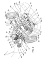
- drive system 20 includes a relatively low horsepower internal combustion engine 30 (i.e., 20 hp) and two conventional electric motors 32 and 34 (i.e., 30-60 hp; DC motors) which deliver power to the drive wheels 36 and 38 of vehicle 10, either individually or concurrently, depending upon the operating conditions of the vehicle.
- the specific power of the engine and the motors will depend upon the size and weight of the vehicle.
- drive system 20 has a transmission assembly 40 having an input shaft 42 for receiving torque from engine 30 and motors 32 and 34, and a differential gear assembly 44 for transferring torque to the drive wheels 36 and 38 of vehicle 10 through primary drive shaft 46.
- Transmission assembly 40 is a multispeed manual transmission equipped with a number of forward speeds, neutral, and reverse. Other configurations are envisioned.
- Engine 30 transfers torque to the input shaft 42 of transmission assembly 40 by way of a secondary drive shaft 50 mounted adjacent the primary drive shaft 46. More particularly, a pulley-type torque converter assembly 52 is associated with engine 30 for transmitting power to the secondary drive shaft 50.
- Torque converter assembly 52 includes a drive pulley 54 mounted to an output shaft of engine 30, a variable diameter driven pulley 56 mounted to secondary drive shaft 60, and a belt 68 operatively connecting the two.
- the torque converter assembly functions as a continuously variable transmission which gradually upshifts as the vehicle accelerates faster allowing the engine to operate at its optimum speeds without placing an undue load thereupon.
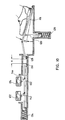
- the torque converter assembly enables vehicle 10 to accelerate from a stationary position to cruising speed using only the small internal combustion engine 30 powered by fuel stored in fuel tank 60 (see Fig. 1). As will be discussed in detail hereinbelow, at times when the engine is used solely to accelerate the vehicle to cruising speed, the electric motors 32 and 34 can be used for rapid acceleration or hill climbing.
- a drive pulley 62 is mounted on secondary drive shaft 50 for transferring torque from drive shaft 50 to a second pulley 64 mounted at the end of the input shaft 42 of transmission assembly 40 by way of a belt 66.
- An overrunning clutch 68 is also mounted on the secondary drive shaft 50 between pulley 56 of torque converter 52 and drive pulley 62, for disengaging engine 30 from the input shaft 42 of transmission assembly 40.
- Overrunning clutches are well known in the art and employ the wedging action of a roller or sprag to automatically engage in one direction and free-wheel in the other direction. Thus, when clutch 68 is disengaged, engine 30 is isolated from the rest of the drive system, thereby reducing any parasitic drag on the system.
- the output shafts 32a and 34a of motors 32 and 34 are connected to the input shaft 42 of transmission assembly 40 by way of belts 72 and 74, respectively. More particularly, belts 72 and 74 deliver torque to respective pulleys 76 and 78 which are mounted side-by-side on the input shaft 42 of transmission assembly 40.
- Overrunning clutches 82 and 84 are operatively associated with pulleys 76 and 78, respectively, to engage input shaft 42 any time the pulleys 76 and 78 turn faster than input shaft 42.
- the electric motors can be triggered by the driver to assist the gas engine in accelerating the vehicle for that period of time. The manner in which this is accomplished will be discussed in greater detail hereinbelow.
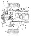
- the drive system of the subject invention also includes a generator 90 (i.e., 15-22 kW) for generating electrical energy to power electric motors 32 and 34.
- Generator 90 is linked to a series of conventional lead-acid batteries 92 arranged along the central axis of the vehicle chassis, as shown in Fig. 1.
- Generator 90 is operatively connected to an output shaft 94 of engine 30 through a set of pulleys and clutches.
- a drive pulley 96 is mounted to an output shaft 94 for driving an intermediary double rim pulley 98 which is mounted on the secondary drive shaft 60.
- a first drive belt 100 extends from drive pulley 96 to the inner rim 98a of pulley 98 to transfer torque therebetween and a second drive belt 102 extends from the outer rim 98b of pulley 98 to a pulley 104 mounted on the input shaft 105 of generator 90 to transfer torque therebetween.
- a first solenoid clutch 108 is operatively associated with drive pulley 96 for selectively engaging pulley 96 under certain operating conditions
- a second solenoid clutch 110 is operatively associated with double rim pulley 98 for engaging pulley 98 under other operating conditions to selectively control the connection of the engine 30 and generator 90.
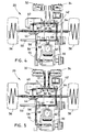
- Figs. 4-9 there is illustrated a series of schematic representations depicting the manner in which power is distributed throughout the drive sy:;tem of the subject invention under various operating conditions.
- the directional arrows indicate the paths by which power is directed to and from the components of drive system 20, and in particular, to the two drive wheels 36 and 38 of the vehicle 10.
- vehicle 10 may accelerate from a stationary position to a predetermined speed, utilizing only the power of internal combustion engine 30.
- power from engine 30 is transferred from output shaft 35 to the secondary drive shaft 50 by way of the torque connector assembly 52, and then to the input shaft 42 of transmission assembly by pulley 62 and 64 and belt 66.
- overrunning clutch 68 is engaged to secondary drive shaft 50, and the overrunning clutches 82 and 84 on input shaft 42 are disengaged, so that during acceleration, electric motors 32 and 34 present no parasitic drag to the system.
- the overrunning clutches 82 and 84 are engaged to enable the deliverance of power from motors 32 and 34 to the input shaft 42 of transmission assembly 40.
- overrunning clutches 82 and 84 The engagement of overrunning clutches 82 and 84 is effectuated by movement of the accelerator pedal of vehicle 10.
- the accelerator pedal 118 which controls the throttle 120 of engine 30 is also linked to two potentiometers 122 and 124 which are operatively connected to motors 32 and 34, respectively.
- ⁇ the angle which is approximately equal to 1/3 the total distance which pedal 118 can travel against the bias of throttle spring 126.
- slider 128 which is linked to pedal 118 translates through a linear distance "x" corresponding to the angular distance " ⁇ ".
- the drive system 20 of the subject invention is also configured so that engine 30 can charge generator 90 while vehicle 10 is operating under the sole power of the gas engine.
- solenoid clutch 108 is engaged and power is transmitted from the output shaft 94 of engine 30 to the input shaft 105 of generator 90 by way of drive belts 100 and 102.
- Solenoid clutch 108 is preferably controlled by a battery charge indicator and an engine speed sensor. Thus, when the batteries 92 are approximately 60% discharged and the engine is operating at a sufficient speed, clutch 108 will engage, permitting engine 30 to drive generator 90.
- clutch 108 disengages, eliminating the parasitic drag of the generator on the system.
- solenoid clutch 110 is disengaged so that the double rim pulley 98 rotates independent of the rotation of the secondary drive shaft 50 which is receiving power from engine 30.
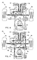
- the drive system 20 of the subject invention also incorporates a regenerative braking sub-system wherein energy is transferred from the drive wheels of vehicle 10 to generator 90 as the transmission assembly is downshifted to slow the vehicle.
- solenoid clutch 108 disengages, allowing engine 30 to return to its idle speed.
- overrunning..clutch 68 which transmits torque in only one direction disengages, since the driven pulley 56 of torque converter 52 is turning slower then the drive pulley 62 on secondary drive shaft 50.
- vehicle 10 is free to coast to a full stop without any parasitic drag from engine 30.
- solenoid clutch 110 engages, causing power to be transmitted from the front wheels to generator 90. During this time, torque is transferred from the input shaft 42 of the downshifting transmission assembly to generator 90 by way of drive belts 66 and 102.
- the drive system of the subject invention is configured to operate in a zero emissions mode wherein power is transmitted to the drive wheels of vehicle 10 solely from electric motors 32 and 34.
- overrunning clutches 82 and 84 are engaged and power is transmitted from motor 32 and 34 to the input shaft 42 of transmission assembly 40 by way of belts 72 and 74, respectively.
- a third solenoid clutch 150 which is mounted on the input shaft 42 of transmission assembly 40 is engaged and pulleys 62 and 64 are rotating so that power will be readily available to generator 90 if the brake pedal of the vehicle is applied.
- overrunning clutch 68 is disengaged so that the engine 30 and torque converter 42 remain stationary.
- Solenoid clutches 108 and 110 are also disengaged at this time, so that all unnecessary parasitic drag is eliminated. Furthermore, since engine 30 is isolated from the rest of the system when the vehicle is operating in a zero emission mode, the first third of the travel of accelerator pedal 118 will produce no response. However, when the pedal is depressed further, the potentiometers which control the speed of motors 32 and 34 will be activated.
- the zero emission mode of operation depicted in Fig. 8 can be selectively chosen by the driver by manipulating a selector switch 160 located on the dashboard of the vehicle (see Fig. 1).
- a selector switch 160 located on the dashboard of the vehicle (see Fig. 1).
- the zero emission mode can be easily selected. This mode may be less advantageous for longer trips due to the storage capacity of the batteries.
- FIG. 9 there is illustrated a schematic representation of the manner in which power is distributed within the drive system 20 of the subject invention when the system is switched from a parallel operating mode to a series operating mode.
- a parallel mode of operation mechanical energy from engine 30 is transmitted directly to the drive wheels together with energy from the electric motors.
- a series mode of operation which is more efficient in stop-and-go traffic than a parallel configuration, power is delivered to the drive wheels only by the electric motors, and the engine is employed to deliver power to the generator.
- the drive system of the subject invention utilizes a computerized controller 170 to switch between the series and parallel modes of operation.
- the system controller monitors all of the control parameters of the drive system including, for example, battery state of charge and vehicle speed, and is electrically connected to each of the interactive components of the drive system.
- the system controller disengages solenoid clutch 150 and engages solenoid clutch 110 so that all of the mechanical energy of engine 30 is transmitted to generator 90 by way of the secondary shaft 50. Since the torque converter is in operation at this time, power generation increases and decreases in proportion to engine speed. In this mode of operation, it is also possible to temporarily engage clutch 150 to send power to the generator from the drive wheels during the regenerative braking periods. At such times, overrunning clutch 68 allows engine 30 to slow to idle speed, thus conserving the energy consumed thereby.
- the subject invention provides a hybrid electric vehicle with several unique components including: (1) a pulley-type torque converter used with an internal combustion engine and a multi-speed transmission; (2) an overrunning clutch allowing the vehicle to be driven on pure electric power without parasitic drag from the internal combustion engine or torque converter; and (3) a clutch allowing the hybrid drive system to switch back and forth between series and parallel configurations.
- the belts and pulleys can all be replaced by a gear box having input and output shafts for the engine, generator, and electric motors.
- the electric and gas engine throttles can be operated by computer controlled actuators instead of the mechanical system described in Fig. 10. This would allow a computer to automatically adjust the duty cycles of the internal combustion engine and electric motors to reach any desired depth of battery discharge after a specified number of miles.
- the energy distribution system of the subject invention can be employed to reduce home energy costs. More particularly, the vehicle can be used as a portable generator to power the home. In such instances, solar panels would be employed to maintain a charge in the batteries for mean power consumption, and the internal combustion engine can be utilized for peak power demands. The engine could be powered by natural gas rather than conventional fuels.
Landscapes
- Engineering & Computer Science (AREA)
- Transportation (AREA)
- Mechanical Engineering (AREA)
- Chemical & Material Sciences (AREA)
- Combustion & Propulsion (AREA)
- Automation & Control Theory (AREA)
- Power Engineering (AREA)
- Sustainable Development (AREA)
- Sustainable Energy (AREA)
- Life Sciences & Earth Sciences (AREA)
- Electric Propulsion And Braking For Vehicles (AREA)
- Hybrid Electric Vehicles (AREA)
- Control Of Driving Devices And Active Controlling Of Vehicle (AREA)
- Control Of Vehicle Engines Or Engines For Specific Uses (AREA)
Claims (11)
- Verfahren für die Energieverteilung in einem Fahrzeug (10), das ein elektrisches Hybridantriebssystem (20) hat, das einen Verbrennungsmotor (30) mit innerer Verbrennung und wenigsten einen, mit einem Energiespeicher gekoppelten Elektromotor (32, 34) enthält, wobei der Verbrennungsmotor (30) und der wenigstens eine Elektromotor (32, 34) ein Drehmoment einer Primärwelle (26) zuführt, die wenigstens zwei ihr im Betrieb zugeordnete Antriebsräder (36, 38) hat, wobei das Verfahren folgende Schritte aufweist:a) Zufuhr eines Drehmoments vom Verbrennungsmotor (30) und vom Elektromotor (32, 34) zur Primärwelle (46), um das Fahrzeug (10) vom Stand bis zu einer vorbestimmten Reisegeschwindigkeit zu beschleunigen;b) Abkoppeln des Elektromotors (32, 34) von der Primärantriebswelle (46), sobald das Fahrzeug (10) auf die Reisegeschwindigkeit beschleunigt hat, zur Verringerung parasitären Zugs auf das System (20);c) Zufuhr von Drehmoment vom Verbrennungsmotor (30) zur Primärantriebswelle (46) unter Nutzung einer mittleren Leistung des Verbrennungsmotors (30), um das Fahrzeug (10) bei der Reisegeschwindigkeit zu halten; undd) Abgleich von Betriebszyklen bei der Übertragung von Drehmoment von dem Verbrennungsmotor (30) und dem wenigstens einen Elektromotor (32, 34), zum Erreichen einer Solltiefe der Entladung des Energiespeichers nach einer spezifizierten Anzahl von Meilen.
- Verfahren nach Anspruch 1,(i) das weiterhin den Schritt aufweist, der den Elektromotor (32, 34) in einem neutralen Zustand hält, so dass er von der Primärantriebswelle (46) zur Verringerung des parasitären Zugs auf das System abgekoppelt ist; oder(ii) das weiterhin den Schritt aufweist, der einen Generator (90) vorsieht, um elektrische Energie für den Energiespeicher und für den Elektromotor (32, 24)für die Nutzung zum Antrieb des Fahrzeugs (10) zu erzeugen.
- Verfahren nach Anspruch 2, Teil (i), das weiterhin einen Schritt eines selektiven Eingriffs des Elektromotors (32, 34) an der Primärantriebswelle (46) aufweist, um den Verbrennungsmotor (30) bei der Beschleunigung des Fahrzeugs (10) auf die Reisegeschwindigkeit zu unterstützen.
- Verfahren nach Anspruch 3, bei dem der Schritt des selektiven Eingriffs des Elektromotors (32, 34) an der Primärantriebswelle (46) das Drücken eines Gaspedals (48) des Fahrzeugs (10) um eine vorbestimmte Distanz umfasst.
- Verfahren nach Anspruch 2, Teil (ii), das einen der folgenden Schritte (a), (b) oder (c) aufweist:a) Das Fahrzeug (10) enthält Bremsen und außerdem weist das Verfahren den Schritt der Übertragung von Drehmoment von den Antriebsrädern (36, 38) zum Generator (90) bei Betätigung der Bremsen auf; oderb) das Verfahren weist weiter den Schritt der Übertragung von Leistung direkt vom Verbrennungsmotor (30) zum Generator (90) auf, während der Elektromotor (32, 34) Leistung direkt zur Primärantriebswelle (46) überträgt; oderc) das Verfahren weist weiterhin den Schritt der Übertragung von Leistung vom Verbrennungsmotor (30) sowohl an den Generator (90) als auch zur Primärantriebswelle (46) auf, während der Elektromotor (32, 34) in neutralem Zustand verbleibt, so dass er von der Primärantriebswelle (46) entkoppelt ist.
- Verfahren nach Anspruch 5, Teil (b), das weiterhin den Schritt eines Eingriffs des Verbrennungsmotors (30) am Generator (90) aufweist, wenn die im Energiespeicher gespeicherte elektrische Energie unter ein vorbestimmtes Mindestniveau fällt.
- Verfahren nach Anspruch 1, das den Schritt der Übertragung von Drehmoment zur Primärantriebswelle (46) vom Verbrennungsmotor (30) und vom Elektromotor (32, 34) mittels einer Getriebebaugruppe (40) und außerdem folgende Schritte aufweist:a) Übertragung von Drehmoment vom Verbrennungsmotor (30) und vom Elektromotor (32, 34) an eine Eingangswelle (42) der Getriebebaugruppe (40), um das Fahrzeug (10) vom Stand bis zu der vorbestimmten Reisegeschwindigkeit zu beschleunigen;b) Abkoppeln des Elektromotors (32, 34) von der Eingangswelle (42) der Getriebebaugruppe (40), sobald das Fahrzeug bis zur Reisegeschwindigkeit beschleunigt hat, um parasitären Zug auf das System (20) zu reduzieren; undc) Übertragen von Drehmoment vom Verbrennungsmotor (30) zur Eingangswelle (42) der Getriebebaugruppe (40) unter Nutzung einer mittleren Leistung des Verbrennungsmotors (30), um das Fahrzeug (10) bei der Reisegeschwindigkeit zu halten.
- Verfahren nach Anspruch 7, bei dem weiterhin(i) ein Schritt, der den Elektromotor (32, 34) in neutralem Zustand so hält, dass er von der Eingangswelle (42) der Getriebebaugruppe (40) entkoppelt ist, um parasitären Zug auf das System (20) zu reduzieren; oder(ii) einen Schritt vorgesehen ist, der einen Generator (90) zur Erzeugung elektrischer Energie für den Energiespeicher und den Elektromotor (32, 34) für dessen Nutzung für den Antrieb des Fahrzeugs (10) vorsieht.
- Verfahren nach Anspruch 8, Teil (i), das weiterhin den Schritt eines selektiven Eingriffs des Elektromotors (32, 34) an der Eingangswelle (42) der Getriebebaugruppe (40) aufweist, um den Verbrennungsmotor (30) bei der Beschleunigung des Fahrzeugs (10) auf die Reisegeschwindigkeit zu unterstützen; oder für den
Teil (ii), weiterhin einen der folgenden Schritte (a) bis (d) aufweist:a) einen Schritt einer Übertragung von Drehmoment von den Antriebsrädern (36, 38) zum Generator (90), wenn die Getriebebaugruppe (40) während des Bremsens herunter geschaltet wird; oderb) einen Schritt der Übertragung von Leistung direkt vom Verbrennungsmotor (30) zum Generator (90), während der Elektromotor (32, 34) Leistung direkt zur Eingangswelle (42) der Getriebebaugruppe (40) überträgt; oderc) einen Schritt, der den Verbrennungsmotor (30) mit dem Generator (90) koppelt, wenn die im Energiespeicher gespeicherte elektrische Energie unter ein vorbestimmtes Mindestniveau fällt; oderd) einen Schritt, der Leistung vom Verbrennungsmotor (30) zum Generator (90) und zur Eingangswelle (42) der Getriebebaugruppe (40) überträgt und gleichzeitig den Elektromotor (32, 34) in einem neutralen Zustand so hält, dass er von der Eingangswelle (42) der Getriebebaugruppe (40) entkoppelt ist. - Verfahren nach Anspruch 9, Teil (i), bei dem der Schritt des selektiven Eingriffs des Elektromotors (32, 34) an der Primärantriebswelle (46) das Drücken eines Gadpedals (118) des Fahrzeugs (10) um eine vorbestimmte Distanz umfasst.
- Verfahren nach Anspruch 1, das einen Generator (90) zur Umwandlung mechanischer Energie in elektrische Energie und Batterien (92) als den Energiespeicher enthält, wobei das Verfahren folgende Schritte aufweist:a) Vorsehen einer ersten Betriebsart, bei der Leistung zur Antriebswelle (46) vom Verbrennungsmotor (30) und vom Elektromotor (32, 34) übertragen wird;b) Vorsehen einer zweiten Betriebsart, bei der Leistung zum Generator (90) vom Verbrennungsmotor (30) und außerdem Leistung vom Elektromotor (32, 34) zur Antriebwelle (46) übertragen wird; undc) Umschalten zwischen der ersten Betriebsart und zweiten Betriebsart unter gewissen vorbestimmten Bedingungen; wobei der Schritt, der zwischen der ersten und zweiten Betriebsart umschaltet, eine Umschaltung von der ersten Betriebsart zur zweiten Betriebsart enthält, wenn die Batterien annähernd 60% oder annähernd 20% entladen sind.
Applications Claiming Priority (3)
| Application Number | Priority Date | Filing Date | Title |
|---|---|---|---|
| US08/455,840 US5704440A (en) | 1995-05-31 | 1995-05-31 | Energy distribution method for hydrid electric vehicle |
| US455840 | 1995-05-31 | ||
| PCT/US1996/008209 WO1996038314A1 (en) | 1995-05-31 | 1996-05-31 | Energy distribution method for hybrid electric vehicle |
Publications (2)
| Publication Number | Publication Date |
|---|---|
| EP0828624A1 EP0828624A1 (de) | 1998-03-18 |
| EP0828624B1 true EP0828624B1 (de) | 2000-12-20 |
Family
ID=23810478
Family Applications (1)
| Application Number | Title | Priority Date | Filing Date |
|---|---|---|---|
| EP96920596A Expired - Lifetime EP0828624B1 (de) | 1995-05-31 | 1996-05-31 | Methode zur energieverteilung für elektrische hybridfahrzeuge |
Country Status (8)
| Country | Link |
|---|---|
| US (1) | US5704440A (de) |
| EP (1) | EP0828624B1 (de) |
| JP (1) | JPH11506517A (de) |
| AT (1) | ATE198179T1 (de) |
| AU (1) | AU720790B2 (de) |
| CA (1) | CA2222431C (de) |
| DE (1) | DE69611296T2 (de) |
| WO (1) | WO1996038314A1 (de) |
Cited By (1)
| Publication number | Priority date | Publication date | Assignee | Title |
|---|---|---|---|---|
| US12115966B2 (en) | 2019-01-24 | 2024-10-15 | Audi Ag | Method for operating a drive for a motor vehicle and corresponding drive device |
Families Citing this family (75)
| Publication number | Priority date | Publication date | Assignee | Title |
|---|---|---|---|---|
| US5689174A (en) * | 1993-08-13 | 1997-11-18 | Pacheco, Sr.; Angel Luis | Electrical power system |
| JP3412352B2 (ja) * | 1995-08-15 | 2003-06-03 | アイシン・エィ・ダブリュ株式会社 | 車両用駆動装置の制御装置 |
| JP3531332B2 (ja) * | 1996-02-29 | 2004-05-31 | トヨタ自動車株式会社 | ハイブリッド駆動装置 |
| JPH09267647A (ja) * | 1996-04-02 | 1997-10-14 | Honda Motor Co Ltd | ハイブリッド車の動力伝達機構 |
| JP3749302B2 (ja) * | 1996-04-11 | 2006-02-22 | トヨタ自動車株式会社 | ハイブリッド車両の駆動制御装置 |
| US5982045A (en) * | 1996-04-19 | 1999-11-09 | Toyota Jidosha Kabushiki Kaisha | Hybrid vehicle drive system adapted to prevent concurrent mode change and transmission shifting or torque distribution ratio change |
| US5887670A (en) * | 1996-05-16 | 1999-03-30 | Toyota Jidosha Kabushiki Kaisha | Vehicle power transmitting system having devices for electrically and mechanically disconnecting power source and vehicle drive wheel upon selection of neutral state |
| US5847470A (en) * | 1996-10-31 | 1998-12-08 | Mitchell; Herman Roosevelt | Auxiliary motor drive system |
| EP0901923B1 (de) * | 1997-09-12 | 2004-10-20 | Honda Giken Kogyo Kabushiki Kaisha | Antriebsvorrichtung für Hybridfahrzeug |
| JP3376262B2 (ja) * | 1997-11-21 | 2003-02-10 | 日産ディーゼル工業株式会社 | ハイブリッド車両の非常駆動装置 |
| US6209672B1 (en) | 1998-09-14 | 2001-04-03 | Paice Corporation | Hybrid vehicle |
| US6338391B1 (en) | 1999-03-01 | 2002-01-15 | Paice Corporation | Hybrid vehicles incorporating turbochargers |
| EP1932704B1 (de) | 1998-09-14 | 2011-10-26 | Paice LLC | Start- und Abschaltsteuerung der Brenkraftmaschine in Hybridfahrzeuge |
| AU6019299A (en) | 1998-09-14 | 2000-04-03 | Paice Corporation | Hybrid vehicles |
| US6554088B2 (en) | 1998-09-14 | 2003-04-29 | Paice Corporation | Hybrid vehicles |
| JP3803205B2 (ja) * | 1998-12-28 | 2006-08-02 | 本田技研工業株式会社 | ハイブリッド自動車 |
| IT1309008B1 (it) * | 1999-02-24 | 2002-01-15 | Vf Venieri S P A | Gruppo di propulsione per veicoli elettrici a quattro ruote motriciper movimento terra e agricoltura |
| GB0007694D0 (en) * | 2000-03-31 | 2000-05-17 | Transportation Tecniques Llc | Vehicle suspension system |
| US6622804B2 (en) * | 2001-01-19 | 2003-09-23 | Transportation Techniques, Llc. | Hybrid electric vehicle and method of selectively operating the hybrid electric vehicle |
| US6483198B2 (en) * | 2001-01-19 | 2002-11-19 | Transportation Techniques Llc | Hybrid electric vehicle having a selective zero emission mode, and method of selectively operating the zero emission mode |
| US6644427B2 (en) | 2001-04-06 | 2003-11-11 | Ise Research Corporation | System and method for providing parallel power in a hybrid-electric vehicle |
| DE10204215A1 (de) | 2002-01-28 | 2003-08-21 | Bombardier Transp Gmbh | Fahrzeug mit Bremsenergiespeicher |
| TWI278165B (en) * | 2002-06-06 | 2007-04-01 | Sunyen Co Ltd | Single body motor/generator dual function device |
| US20040004412A1 (en) * | 2002-07-08 | 2004-01-08 | Kochuvettukattil Shilumon Joseph | Self energetic motors and generators |
| US6966882B2 (en) | 2002-11-25 | 2005-11-22 | Tibion Corporation | Active muscle assistance device and method |
| JP3896973B2 (ja) * | 2003-02-25 | 2007-03-22 | 株式会社デンソー | 車両用電気系の管理方法 |
| US7008342B2 (en) * | 2003-08-15 | 2006-03-07 | Silvatech Global Systems Ltd. | Electro-mechanical continuously variable transmission |
| US7127337B2 (en) * | 2003-10-14 | 2006-10-24 | General Motors Corporation | Silent operating mode for reducing emissions of a hybrid electric vehicle |
| US7190133B2 (en) * | 2004-06-28 | 2007-03-13 | General Electric Company | Energy storage system and method for hybrid propulsion |
| US20060010844A1 (en) * | 2004-06-30 | 2006-01-19 | Self Guided Systems, L.L.C. | Unmanned utility vehicle |
| US20060016627A1 (en) * | 2004-07-22 | 2006-01-26 | Harold Robertson | Bifurcated electrical vehicle motor |
| US20060059880A1 (en) * | 2004-09-13 | 2006-03-23 | Angott Paul G | Unmanned utility vehicle |
| JP3998016B2 (ja) | 2004-11-12 | 2007-10-24 | トヨタ自動車株式会社 | 車両用駆動装置 |
| FR2883805B1 (fr) * | 2005-03-29 | 2007-07-06 | Peugeot Citroen Automobiles Sa | Groupe motopropulseur hybride pour vehicule automobile |
| US7811189B2 (en) * | 2005-12-30 | 2010-10-12 | Tibion Corporation | Deflector assembly |
| US20070155558A1 (en) * | 2005-12-30 | 2007-07-05 | Horst Robert W | Continuously variable transmission |
| DE102006005477B4 (de) * | 2006-02-03 | 2007-10-11 | Veit Wilhelm | Vorrichtung zur Erzeugung von Strom, sowie Kraftfahrzeug mit Elektroantrieb und solcher Vorrichtung |
| AU2007234883A1 (en) | 2006-04-03 | 2007-10-18 | Bluwav Systems, Llc | Vehicle power unit designed as retrofittable axle comprising motor, battery and suspension |
| GB2436855A (en) * | 2006-04-05 | 2007-10-10 | David Davies | Combustion apparatus, eg diesel engine, with exhaust gas recirculation |
| US20070261902A1 (en) * | 2006-05-15 | 2007-11-15 | George Margoudakis | Electric motor vehicle |
| US8353854B2 (en) * | 2007-02-14 | 2013-01-15 | Tibion Corporation | Method and devices for moving a body joint |
| US20080288132A1 (en) | 2007-05-16 | 2008-11-20 | General Electric Company | Method of operating vehicle and associated system |
| US8052629B2 (en) | 2008-02-08 | 2011-11-08 | Tibion Corporation | Multi-fit orthotic and mobility assistance apparatus |
| US8089168B2 (en) * | 2008-04-15 | 2012-01-03 | Claude Chevrette | Tire actuated generator for use on cars |
| EP2271531B2 (de) * | 2008-04-28 | 2018-11-07 | Mack Trucks, Inc. | Antriebsstrang mit eingangswelle und motordrehzahlsynchronisierung und verfahren zum schalten von gängen in einem antriebsstrang |
| US20090306548A1 (en) * | 2008-06-05 | 2009-12-10 | Bhugra Kern S | Therapeutic method and device for rehabilitation |
| US8011464B2 (en) * | 2008-07-24 | 2011-09-06 | GM Global Technology Operations LLC | Electric drive system with a selectable one-way clutch |
| US8274244B2 (en) * | 2008-08-14 | 2012-09-25 | Tibion Corporation | Actuator system and method for extending a joint |
| US8058823B2 (en) * | 2008-08-14 | 2011-11-15 | Tibion Corporation | Actuator system with a multi-motor assembly for extending and flexing a joint |
| US7779943B2 (en) * | 2008-10-08 | 2010-08-24 | Bosye, Llc | Hybrid-powered slow-speed vehicle, vehicle travel-range extension method, and method of hybrid-vehicle manufacture |
| US20100164233A1 (en) * | 2008-10-14 | 2010-07-01 | Bobby Lewis Bates | Centrifugal torque amplifyer |
| CA2745276C (en) * | 2008-12-03 | 2016-06-28 | Mato Barbic | Intermittant electrical charging ac/dc driving system |
| US8072172B2 (en) * | 2008-12-17 | 2011-12-06 | Honeywell International Inc. | Redundant electromechanical actuator for control surfaces |
| US20100204620A1 (en) * | 2009-02-09 | 2010-08-12 | Smith Jonathan A | Therapy and mobility assistance system |
| US8639455B2 (en) | 2009-02-09 | 2014-01-28 | Alterg, Inc. | Foot pad device and method of obtaining weight data |
| US8643201B2 (en) * | 2010-03-01 | 2014-02-04 | Obie Scott | Generator system for recovering vehicle and resident wasted energy |
| US20120112710A1 (en) * | 2010-11-05 | 2012-05-10 | Ross George Haldeman | Electric machine to regulate work output rotational speed from infinitely variable transmissions by the creation of electrical energy |
| EP2463169A1 (de) * | 2010-12-08 | 2012-06-13 | Saab Automobile AB | Hybridfahrzeug |
| DE102010056034A1 (de) | 2010-12-15 | 2012-06-21 | Getrag Getriebe- Und Zahnradfabrik Hermann Hagenmeyer Gmbh & Cie Kg | Verfahren zum Betreiben einer Antriebsvorrichtung eines Fahrzeugs, Vorrichtung, Computer-Programmprodukt |
| US9132735B2 (en) * | 2011-02-17 | 2015-09-15 | George Black | Electric car systems |
| US8720618B1 (en) | 2011-03-28 | 2014-05-13 | Aura Systems Inc. | Retrofitting a vehicle to transfer mechanical power out of an engine compartment |
| US9511761B2 (en) | 2012-10-19 | 2016-12-06 | Kubota Corporation | Hybrid vehicle |
| US9085222B1 (en) * | 2013-01-31 | 2015-07-21 | David Brian McParland | Electrical propulsion and recharging technology for heavy duty vehicles |
| WO2014151584A1 (en) | 2013-03-15 | 2014-09-25 | Alterg, Inc. | Orthotic device drive system and method |
| JP2015051686A (ja) * | 2013-09-06 | 2015-03-19 | トヨタ自動車株式会社 | 車両の駆動制御装置 |
| US10144410B2 (en) * | 2014-04-24 | 2018-12-04 | Volvo Construction Equipment Ab | Apparatus for calculating operational time of hybrid construction machine and method therefor |
| US9630524B1 (en) | 2014-08-14 | 2017-04-25 | Kandas Conde | Electric vehicle |
| US10099675B2 (en) * | 2014-10-27 | 2018-10-16 | GM Global Technology Operations LLC | System and method for improving fuel economy and reducing emissions when a vehicle is decelerating |
| CN105997381B (zh) * | 2016-05-04 | 2017-09-05 | 许金华 | 一种轮椅 |
| CN110770061A (zh) * | 2017-06-16 | 2020-02-07 | 利滕斯汽车合伙公司 | 允许通过电动马达驱动车辆的驱动装置 |
| US20180362014A1 (en) * | 2017-06-20 | 2018-12-20 | A Truly Electric Car Company | Adaptive power supply for electric cars |
| DE102017221775A1 (de) * | 2017-12-04 | 2019-06-06 | Bayerische Motoren Werke Aktiengesellschaft | Hybridantriebsstrang |
| JP7276686B2 (ja) * | 2019-02-27 | 2023-05-18 | マツダ株式会社 | 車両駆動装置 |
| CN110649757A (zh) * | 2019-08-22 | 2020-01-03 | 武汉理工大学 | 一种无人驾驶测试平台车电驱动系统 |
| US11407302B2 (en) * | 2020-02-26 | 2022-08-09 | Borgwarner Inc. | Torque transfer assembly and vehicle including the same |
Family Cites Families (35)
| Publication number | Priority date | Publication date | Assignee | Title |
|---|---|---|---|---|
| US2571284A (en) * | 1946-07-06 | 1951-10-16 | Chrysler Corp | Power transmission |
| US2506809A (en) * | 1947-08-12 | 1950-05-09 | Chrysler Corp | Generator-motor driving system |
| US2666492A (en) * | 1948-01-23 | 1954-01-19 | Chrysler Corp | Electromechanical change-speed transmission and brake control for vehicles |
| US3205965A (en) * | 1961-08-04 | 1965-09-14 | Linde Eismasch Ag | Motor vehicle |
| US3503464A (en) * | 1968-03-04 | 1970-03-31 | Michel N Yardney | Control system for a battery and hydrocarbon powered vehicle |
| US3732751A (en) * | 1969-03-17 | 1973-05-15 | Trw Inc | Power train using multiple power sources |
| DE2133485A1 (de) * | 1971-07-06 | 1973-01-25 | Bosch Gmbh Robert | Kraftfahrzeug mit einem hybridantrieb |
| DE2153961A1 (de) * | 1971-10-29 | 1973-05-03 | Volkswagenwerk Ag | Hybrid-antrieb |
| US4042056A (en) * | 1975-11-21 | 1977-08-16 | Automobile Corporation Of America | Hybrid powered automobile |
| FR2360439A1 (fr) * | 1976-08-06 | 1978-03-03 | Renault | Dispositif de transmission hybride pour vehicules automobiles a moteur thermique |
| US4165795A (en) * | 1978-02-17 | 1979-08-28 | Gould Inc. | Hybrid automobile |
| US4313080A (en) * | 1978-05-22 | 1982-01-26 | Battery Development Corporation | Method of charge control for vehicle hybrid drive batteries |
| US4351405A (en) * | 1978-10-12 | 1982-09-28 | Hybricon Inc. | Hybrid car with electric and heat engine |
| US4438342A (en) * | 1980-05-15 | 1984-03-20 | Kenyon Keith E | Novel hybrid electric vehicle |
| US4423794A (en) * | 1981-03-12 | 1984-01-03 | The Garrett Corporation | Flywheel assisted electro-mechanical drive system |
| GB8323482D0 (en) * | 1983-09-01 | 1983-10-05 | Lucas Chloride Ev Syst Ltd | Vehicle propulsion system |
| JPS62104403A (ja) * | 1985-10-29 | 1987-05-14 | Isuzu Motors Ltd | 車両駆動装置 |
| US5176213A (en) * | 1987-12-09 | 1993-01-05 | Aisin Aw Co., Ltd. | Driving force distribution system for hybrid vehicles |
| GB2219671B (en) * | 1988-04-26 | 1993-01-13 | Joseph Frank Kos | Computer controlled optimized hybrid engine |
| DE3940172A1 (de) * | 1989-12-05 | 1991-06-06 | Audi Ag | Fahrzeug mit zwei achsen |
| US5125469A (en) * | 1991-03-04 | 1992-06-30 | Scott Gerald A | System for storing and using deceleration energy |
| US5172784A (en) * | 1991-04-19 | 1992-12-22 | Varela Jr Arthur A | Hybrid electric propulsion system |
| IT1246063B (it) * | 1991-04-23 | 1994-11-07 | Iveco Fiat | Gruppo propulsore per un autoveicolo provvisto di mezzi motori azionati per via termica e di mezzi motori azionati per via elettrica |
| DE4202083C2 (de) * | 1992-01-25 | 1994-01-20 | Daimler Benz Ag | Hybridantrieb für ein Kraftfahrzeug |
| US5327987A (en) * | 1992-04-02 | 1994-07-12 | Abdelmalek Fawzy T | High efficiency hybrid car with gasoline engine, and electric battery powered motor |
| US5301764A (en) * | 1992-04-13 | 1994-04-12 | Gardner Conrad O | Hybrid motor vehicle having an electric motor and utilizing an internal combustion engine for fast charge during cruise mode off condition |
| JPH07507977A (ja) * | 1992-05-08 | 1995-09-07 | フィールド,ブルース エフ. | 電気ハイブリッド車両 |
| DE4217668C1 (de) * | 1992-05-28 | 1993-05-06 | Daimler Benz Ag | Verfahren zur Steuerung eines ein Fahrzeug antreibenden Hybridantriebes |
| US5255733A (en) * | 1992-08-10 | 1993-10-26 | Ford Motor Company | Hybird vehicle cooling system |
| US5318142A (en) * | 1992-11-05 | 1994-06-07 | Ford Motor Company | Hybrid drive system |
| US5291960A (en) * | 1992-11-30 | 1994-03-08 | Ford Motor Company | Hybrid electric vehicle regenerative braking energy recovery system |
| US5264764A (en) * | 1992-12-21 | 1993-11-23 | Ford Motor Company | Method for controlling the operation of a range extender for a hybrid electric vehicle |
| US5285111A (en) * | 1993-04-27 | 1994-02-08 | General Motors Corporation | Integrated hybrid transmission with inertia assisted launch |
| DE69320046T2 (de) * | 1993-10-14 | 1999-04-01 | Nicolo Doveri | Hybridantriebssystem für Fahrzeuge, insbesondere für den städtischen Gebrauch |
| US5359308A (en) * | 1993-10-27 | 1994-10-25 | Ael Defense Corp. | Vehicle energy management system using superconducting magnetic energy storage |
-
1995
- 1995-05-31 US US08/455,840 patent/US5704440A/en not_active Expired - Fee Related
-
1996
- 1996-05-31 WO PCT/US1996/008209 patent/WO1996038314A1/en not_active Ceased
- 1996-05-31 EP EP96920596A patent/EP0828624B1/de not_active Expired - Lifetime
- 1996-05-31 AT AT96920596T patent/ATE198179T1/de active
- 1996-05-31 JP JP8536722A patent/JPH11506517A/ja active Pending
- 1996-05-31 AU AU58854/96A patent/AU720790B2/en not_active Ceased
- 1996-05-31 DE DE69611296T patent/DE69611296T2/de not_active Expired - Fee Related
- 1996-05-31 CA CA002222431A patent/CA2222431C/en not_active Expired - Fee Related
Cited By (1)
| Publication number | Priority date | Publication date | Assignee | Title |
|---|---|---|---|---|
| US12115966B2 (en) | 2019-01-24 | 2024-10-15 | Audi Ag | Method for operating a drive for a motor vehicle and corresponding drive device |
Also Published As
| Publication number | Publication date |
|---|---|
| DE69611296T2 (de) | 2001-04-26 |
| ATE198179T1 (de) | 2001-01-15 |
| AU720790B2 (en) | 2000-06-15 |
| AU5885496A (en) | 1996-12-18 |
| CA2222431C (en) | 2007-01-30 |
| DE69611296D1 (de) | 2001-01-25 |
| CA2222431A1 (en) | 1996-12-05 |
| EP0828624A1 (de) | 1998-03-18 |
| JPH11506517A (ja) | 1999-06-08 |
| US5704440A (en) | 1998-01-06 |
| WO1996038314A1 (en) | 1996-12-05 |
Similar Documents
| Publication | Publication Date | Title |
|---|---|---|
| EP0828624B1 (de) | Methode zur energieverteilung für elektrische hybridfahrzeuge | |
| CA2222531C (en) | Drive system for hybrid electric vehicle | |
| US5558595A (en) | One-mode, input-split, parallel, hybrid transmission | |
| US6307277B1 (en) | Apparatus and method for a torque and fuel control system for a hybrid vehicle | |
| US6110066A (en) | Parallel hybrid drivetrain | |
| US10525968B2 (en) | Method for controlling a drive device of a hybrid vehicle and hybrid vehicle | |
| US7398845B2 (en) | Controller and control method for a hybrid electric vehicle powertrain | |
| US7004869B2 (en) | Transfer case for hybrid vehicle | |
| US6464608B2 (en) | Transfer case for hybrid vehicle | |
| EP0769403B1 (de) | Hybridfahrzeug-Antriebssystem mit zwei Motor/Generator Einheiten und mit Verbrennungsmotor-Startmitteln | |
| US7647994B1 (en) | Hybrid vehicle having an electric generator engine and an auxiliary accelerator engine | |
| EP0634980B1 (de) | ANTRIEBSSTRANG MIT VORRICHTUNG ZUR ERFASSUNG UND KORREKTUR DES RèCKROLLZUSTANDES EINES ELEKTRISCHEN FAHRZEUGS | |
| GB2406318A (en) | A hybrid vehicle powertrain with improved reverse drive performance | |
| JP2007182215A (ja) | ハイブリッド駆動車両 | |
| US10144411B2 (en) | Vehicle system | |
| US20250381834A1 (en) | Drive apparatus for vehicle |
Legal Events
| Date | Code | Title | Description |
|---|---|---|---|
| PUAI | Public reference made under article 153(3) epc to a published international application that has entered the european phase |
Free format text: ORIGINAL CODE: 0009012 |
|
| 17P | Request for examination filed |
Effective date: 19971126 |
|
| AK | Designated contracting states |
Kind code of ref document: A1 Designated state(s): AT BE CH DE DK ES FI FR GB GR IE IT LI LU MC NL PT SE |
|
| 17Q | First examination report despatched |
Effective date: 19980612 |
|
| GRAG | Despatch of communication of intention to grant |
Free format text: ORIGINAL CODE: EPIDOS AGRA |
|
| 17Q | First examination report despatched |
Effective date: 19980612 |
|
| GRAG | Despatch of communication of intention to grant |
Free format text: ORIGINAL CODE: EPIDOS AGRA |
|
| GRAH | Despatch of communication of intention to grant a patent |
Free format text: ORIGINAL CODE: EPIDOS IGRA |
|
| GRAH | Despatch of communication of intention to grant a patent |
Free format text: ORIGINAL CODE: EPIDOS IGRA |
|
| GRAA | (expected) grant |
Free format text: ORIGINAL CODE: 0009210 |
|
| AK | Designated contracting states |
Kind code of ref document: B1 Designated state(s): AT BE CH DE DK ES FI FR GB GR IE IT LI LU MC NL PT SE |
|
| PG25 | Lapsed in a contracting state [announced via postgrant information from national office to epo] |
Ref country code: SE Free format text: THE PATENT HAS BEEN ANNULLED BY A DECISION OF A NATIONAL AUTHORITY Effective date: 20001220 Ref country code: NL Free format text: LAPSE BECAUSE OF FAILURE TO SUBMIT A TRANSLATION OF THE DESCRIPTION OR TO PAY THE FEE WITHIN THE PRESCRIBED TIME-LIMIT Effective date: 20001220 Ref country code: LI Free format text: LAPSE BECAUSE OF FAILURE TO SUBMIT A TRANSLATION OF THE DESCRIPTION OR TO PAY THE FEE WITHIN THE PRESCRIBED TIME-LIMIT Effective date: 20001220 Ref country code: IT Free format text: LAPSE BECAUSE OF FAILURE TO SUBMIT A TRANSLATION OF THE DESCRIPTION OR TO PAY THE FEE WITHIN THE PRE;WARNING: LAPSES OF ITALIAN PATENTS WITH EFFECTIVE DATE BEFORE 2007 MAY HAVE OCCURRED AT ANY TIME BEFORE 2007. THE CORRECT EFFECTIVE DATE MAY BE DIFFERENT FROM THE ONE RECORDED.SCRIBED TIME-LIMIT Effective date: 20001220 Ref country code: FI Free format text: LAPSE BECAUSE OF FAILURE TO SUBMIT A TRANSLATION OF THE DESCRIPTION OR TO PAY THE FEE WITHIN THE PRESCRIBED TIME-LIMIT Effective date: 20001220 Ref country code: ES Free format text: THE PATENT HAS BEEN ANNULLED BY A DECISION OF A NATIONAL AUTHORITY Effective date: 20001220 Ref country code: CH Free format text: LAPSE BECAUSE OF FAILURE TO SUBMIT A TRANSLATION OF THE DESCRIPTION OR TO PAY THE FEE WITHIN THE PRESCRIBED TIME-LIMIT Effective date: 20001220 Ref country code: BE Free format text: LAPSE BECAUSE OF FAILURE TO SUBMIT A TRANSLATION OF THE DESCRIPTION OR TO PAY THE FEE WITHIN THE PRESCRIBED TIME-LIMIT Effective date: 20001220 Ref country code: AT Free format text: LAPSE BECAUSE OF FAILURE TO SUBMIT A TRANSLATION OF THE DESCRIPTION OR TO PAY THE FEE WITHIN THE PRESCRIBED TIME-LIMIT Effective date: 20001220 |
|
| REF | Corresponds to: |
Ref document number: 198179 Country of ref document: AT Date of ref document: 20010115 Kind code of ref document: T |
|
| REG | Reference to a national code |
Ref country code: CH Ref legal event code: EP |
|
| REG | Reference to a national code |
Ref country code: IE Ref legal event code: FG4D |
|
| REF | Corresponds to: |
Ref document number: 69611296 Country of ref document: DE Date of ref document: 20010125 |
|
| ET | Fr: translation filed | ||
| PG25 | Lapsed in a contracting state [announced via postgrant information from national office to epo] |
Ref country code: PT Free format text: LAPSE BECAUSE OF FAILURE TO SUBMIT A TRANSLATION OF THE DESCRIPTION OR TO PAY THE FEE WITHIN THE PRESCRIBED TIME-LIMIT Effective date: 20010320 Ref country code: DK Free format text: LAPSE BECAUSE OF FAILURE TO SUBMIT A TRANSLATION OF THE DESCRIPTION OR TO PAY THE FEE WITHIN THE PRESCRIBED TIME-LIMIT Effective date: 20010320 |
|
| PG25 | Lapsed in a contracting state [announced via postgrant information from national office to epo] |
Ref country code: GR Free format text: LAPSE BECAUSE OF FAILURE TO SUBMIT A TRANSLATION OF THE DESCRIPTION OR TO PAY THE FEE WITHIN THE PRESCRIBED TIME-LIMIT Effective date: 20010323 |
|
| NLV1 | Nl: lapsed or annulled due to failure to fulfill the requirements of art. 29p and 29m of the patents act | ||
| PG25 | Lapsed in a contracting state [announced via postgrant information from national office to epo] |
Ref country code: MC Free format text: LAPSE BECAUSE OF NON-PAYMENT OF DUE FEES Effective date: 20010531 Ref country code: LU Free format text: LAPSE BECAUSE OF NON-PAYMENT OF DUE FEES Effective date: 20010531 Ref country code: IE Free format text: LAPSE BECAUSE OF NON-PAYMENT OF DUE FEES Effective date: 20010531 |
|
| REG | Reference to a national code |
Ref country code: CH Ref legal event code: PL |
|
| PLBE | No opposition filed within time limit |
Free format text: ORIGINAL CODE: 0009261 |
|
| STAA | Information on the status of an ep patent application or granted ep patent |
Free format text: STATUS: NO OPPOSITION FILED WITHIN TIME LIMIT |
|
| 26N | No opposition filed | ||
| REG | Reference to a national code |
Ref country code: GB Ref legal event code: IF02 |
|
| REG | Reference to a national code |
Ref country code: IE Ref legal event code: MM4A |
|
| PGFP | Annual fee paid to national office [announced via postgrant information from national office to epo] |
Ref country code: DE Payment date: 20070531 Year of fee payment: 12 |
|
| PGFP | Annual fee paid to national office [announced via postgrant information from national office to epo] |
Ref country code: GB Payment date: 20070530 Year of fee payment: 12 |
|
| PGFP | Annual fee paid to national office [announced via postgrant information from national office to epo] |
Ref country code: FR Payment date: 20070525 Year of fee payment: 12 |
|
| GBPC | Gb: european patent ceased through non-payment of renewal fee |
Effective date: 20080531 |
|
| REG | Reference to a national code |
Ref country code: FR Ref legal event code: ST Effective date: 20090119 |
|
| PG25 | Lapsed in a contracting state [announced via postgrant information from national office to epo] |
Ref country code: FR Free format text: LAPSE BECAUSE OF NON-PAYMENT OF DUE FEES Effective date: 20080602 Ref country code: DE Free format text: LAPSE BECAUSE OF NON-PAYMENT OF DUE FEES Effective date: 20081202 |
|
| PG25 | Lapsed in a contracting state [announced via postgrant information from national office to epo] |
Ref country code: GB Free format text: LAPSE BECAUSE OF NON-PAYMENT OF DUE FEES Effective date: 20080531 |