EP0829008B1 - Verfahren und vorrichtung zur taupunkttemperaturmessung eines feuchten gases - Google Patents
Verfahren und vorrichtung zur taupunkttemperaturmessung eines feuchten gases Download PDFInfo
- Publication number
- EP0829008B1 EP0829008B1 EP96919929A EP96919929A EP0829008B1 EP 0829008 B1 EP0829008 B1 EP 0829008B1 EP 96919929 A EP96919929 A EP 96919929A EP 96919929 A EP96919929 A EP 96919929A EP 0829008 B1 EP0829008 B1 EP 0829008B1
- Authority
- EP
- European Patent Office
- Prior art keywords
- dew point
- temperature
- moisture
- moisture content
- point temperature
- Prior art date
- Legal status (The legal status is an assumption and is not a legal conclusion. Google has not performed a legal analysis and makes no representation as to the accuracy of the status listed.)
- Expired - Lifetime
Links
- 238000000034 method Methods 0.000 title claims description 34
- 238000001816 cooling Methods 0.000 claims description 62
- 238000009833 condensation Methods 0.000 claims description 46
- 230000005494 condensation Effects 0.000 claims description 46
- 230000007423 decrease Effects 0.000 claims description 31
- 238000001704 evaporation Methods 0.000 claims description 23
- 230000008020 evaporation Effects 0.000 claims description 23
- 238000009529 body temperature measurement Methods 0.000 claims description 16
- 238000005259 measurement Methods 0.000 claims description 15
- 238000012545 processing Methods 0.000 claims description 15
- 238000011144 upstream manufacturing Methods 0.000 claims description 15
- 238000012544 monitoring process Methods 0.000 claims description 13
- 239000013078 crystal Substances 0.000 claims description 11
- 238000001514 detection method Methods 0.000 claims description 9
- 238000010438 heat treatment Methods 0.000 claims description 9
- 239000007788 liquid Substances 0.000 claims description 8
- 230000001419 dependent effect Effects 0.000 claims description 7
- 239000004020 conductor Substances 0.000 claims description 4
- 239000003507 refrigerant Substances 0.000 claims description 4
- 230000003247 decreasing effect Effects 0.000 claims description 3
- 230000008569 process Effects 0.000 claims description 3
- 239000007789 gas Substances 0.000 description 90
- XLYOFNOQVPJJNP-UHFFFAOYSA-N water Substances O XLYOFNOQVPJJNP-UHFFFAOYSA-N 0.000 description 25
- 239000003570 air Substances 0.000 description 21
- 239000010931 gold Substances 0.000 description 9
- PCHJSUWPFVWCPO-UHFFFAOYSA-N gold Chemical compound [Au] PCHJSUWPFVWCPO-UHFFFAOYSA-N 0.000 description 8
- 229910052737 gold Inorganic materials 0.000 description 8
- 230000008859 change Effects 0.000 description 7
- VYPSYNLAJGMNEJ-UHFFFAOYSA-N Silicium dioxide Chemical compound O=[Si]=O VYPSYNLAJGMNEJ-UHFFFAOYSA-N 0.000 description 6
- BASFCYQUMIYNBI-UHFFFAOYSA-N platinum Chemical compound [Pt] BASFCYQUMIYNBI-UHFFFAOYSA-N 0.000 description 6
- 239000012080 ambient air Substances 0.000 description 5
- 239000012774 insulation material Substances 0.000 description 5
- 239000011651 chromium Substances 0.000 description 4
- 239000000463 material Substances 0.000 description 4
- 230000004044 response Effects 0.000 description 4
- PNEYBMLMFCGWSK-UHFFFAOYSA-N Alumina Chemical compound [O-2].[O-2].[O-2].[Al+3].[Al+3] PNEYBMLMFCGWSK-UHFFFAOYSA-N 0.000 description 3
- VYZAMTAEIAYCRO-UHFFFAOYSA-N Chromium Chemical compound [Cr] VYZAMTAEIAYCRO-UHFFFAOYSA-N 0.000 description 3
- XUIMIQQOPSSXEZ-UHFFFAOYSA-N Silicon Chemical compound [Si] XUIMIQQOPSSXEZ-UHFFFAOYSA-N 0.000 description 3
- 230000008901 benefit Effects 0.000 description 3
- 238000011088 calibration curve Methods 0.000 description 3
- 229910052804 chromium Inorganic materials 0.000 description 3
- 238000004519 manufacturing process Methods 0.000 description 3
- 229910052697 platinum Inorganic materials 0.000 description 3
- 229910021426 porous silicon Inorganic materials 0.000 description 3
- 229920006395 saturated elastomer Polymers 0.000 description 3
- 229910052710 silicon Inorganic materials 0.000 description 3
- 239000010703 silicon Substances 0.000 description 3
- IJGRMHOSHXDMSA-UHFFFAOYSA-N Atomic nitrogen Chemical compound N#N IJGRMHOSHXDMSA-UHFFFAOYSA-N 0.000 description 2
- 239000004411 aluminium Substances 0.000 description 2
- 229910052782 aluminium Inorganic materials 0.000 description 2
- XAGFODPZIPBFFR-UHFFFAOYSA-N aluminium Chemical compound [Al] XAGFODPZIPBFFR-UHFFFAOYSA-N 0.000 description 2
- 239000000428 dust Substances 0.000 description 2
- 239000012530 fluid Substances 0.000 description 2
- 231100001261 hazardous Toxicity 0.000 description 2
- 229910052751 metal Inorganic materials 0.000 description 2
- 239000002184 metal Substances 0.000 description 2
- 230000035945 sensitivity Effects 0.000 description 2
- 229910052814 silicon oxide Inorganic materials 0.000 description 2
- 229910001220 stainless steel Inorganic materials 0.000 description 2
- 239000010935 stainless steel Substances 0.000 description 2
- 239000013526 supercooled liquid Substances 0.000 description 2
- 238000012935 Averaging Methods 0.000 description 1
- 239000004215 Carbon black (E152) Substances 0.000 description 1
- ZAMOUSCENKQFHK-UHFFFAOYSA-N Chlorine atom Chemical compound [Cl] ZAMOUSCENKQFHK-UHFFFAOYSA-N 0.000 description 1
- VEXZGXHMUGYJMC-UHFFFAOYSA-N Hydrochloric acid Chemical compound Cl VEXZGXHMUGYJMC-UHFFFAOYSA-N 0.000 description 1
- 229920000271 Kevlar® Polymers 0.000 description 1
- 230000004888 barrier function Effects 0.000 description 1
- 230000015572 biosynthetic process Effects 0.000 description 1
- 239000003990 capacitor Substances 0.000 description 1
- 230000015556 catabolic process Effects 0.000 description 1
- 239000003054 catalyst Substances 0.000 description 1
- 239000000460 chlorine Substances 0.000 description 1
- 229910052801 chlorine Inorganic materials 0.000 description 1
- 230000000052 comparative effect Effects 0.000 description 1
- 230000007797 corrosion Effects 0.000 description 1
- 238000005260 corrosion Methods 0.000 description 1
- 125000004122 cyclic group Chemical group 0.000 description 1
- 238000006731 degradation reaction Methods 0.000 description 1
- 238000013461 design Methods 0.000 description 1
- 230000000694 effects Effects 0.000 description 1
- 230000005611 electricity Effects 0.000 description 1
- 239000011521 glass Substances 0.000 description 1
- 229930195733 hydrocarbon Natural products 0.000 description 1
- 150000002430 hydrocarbons Chemical class 0.000 description 1
- 239000012212 insulator Substances 0.000 description 1
- 239000004761 kevlar Substances 0.000 description 1
- 238000000691 measurement method Methods 0.000 description 1
- 238000012986 modification Methods 0.000 description 1
- 230000004048 modification Effects 0.000 description 1
- 238000000465 moulding Methods 0.000 description 1
- 229910052757 nitrogen Inorganic materials 0.000 description 1
- 239000003921 oil Substances 0.000 description 1
- 230000003287 optical effect Effects 0.000 description 1
- 239000013307 optical fiber Substances 0.000 description 1
- 230000010355 oscillation Effects 0.000 description 1
- 239000002245 particle Substances 0.000 description 1
- 230000000737 periodic effect Effects 0.000 description 1
- 229920001296 polysiloxane Polymers 0.000 description 1
- 229920001343 polytetrafluoroethylene Polymers 0.000 description 1
- 239000004810 polytetrafluoroethylene Substances 0.000 description 1
- 239000011148 porous material Substances 0.000 description 1
- 238000010926 purge Methods 0.000 description 1
- 230000000246 remedial effect Effects 0.000 description 1
- 239000004065 semiconductor Substances 0.000 description 1
- 238000011896 sensitive detection Methods 0.000 description 1
- 239000000377 silicon dioxide Substances 0.000 description 1
- LIVNPJMFVYWSIS-UHFFFAOYSA-N silicon monoxide Chemical compound [Si-]#[O+] LIVNPJMFVYWSIS-UHFFFAOYSA-N 0.000 description 1
- 238000012360 testing method Methods 0.000 description 1
- 238000010792 warming Methods 0.000 description 1
Images


Classifications
-
- G—PHYSICS
- G01—MEASURING; TESTING
- G01N—INVESTIGATING OR ANALYSING MATERIALS BY DETERMINING THEIR CHEMICAL OR PHYSICAL PROPERTIES
- G01N25/00—Investigating or analyzing materials by the use of thermal means
- G01N25/56—Investigating or analyzing materials by the use of thermal means by investigating moisture content
- G01N25/66—Investigating or analyzing materials by the use of thermal means by investigating moisture content by investigating dew-point
- G01N25/68—Investigating or analyzing materials by the use of thermal means by investigating moisture content by investigating dew-point by varying the temperature of a condensing surface
Definitions
- the temperature of the mirror may be controlled in order to maintain it at an equilibrium temperature where the rates of condensation and evaporation of water molecules onto or from the mirror surface are equal and a constant mass of water (or frost) is maintained on the mirror thereby providing a constant level of scattering and hence of the light level detected. This occurs at the dew point temperature.
- This type of apparatus is often referred to as a chilled mirror hygrometer.
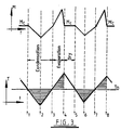
- the average value of the dew point temperature is obtained by calculating the average temperature of the surface over several such cycles.
- the average temperature of the cooling surface may be determined by any suitable technique including simply determining the midpoint of the upper and lower temperature peaks of said cycle, or by more sophisticated analysis of the form of the temperature curve cycles as discussed further hereinbelow. Whichever particular method is used though, it is a particular advantage of the present invention that by using a rapid and sensitive detection of condensation onto or evaporation from the surface with changing temperature thereof, the temperature range of the cyclic temperature variation of the surface can be substantially restricted as compared with the prior art, typically to less than 1°C, for example to around ⁇ 0.1°C relative to the actual dew point temperature thereby enabling significantly more accurate measurements to be made.
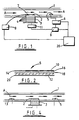
- the arrangement comprises a further moisture sensor 13 disposed upstream of the surface 2 and of the same type as the moisture sensor 5 disposed downstream of the surface 2.
- the capacitance output of the upstream sensor 13 is converted to an analogue or digital signal by a convertor (not shown), the output of the convertor being fed to the microprocessor 20.
- the signal from the convertor 6 for the downstream sensor 5 is fed directly to the microprocessor 20.
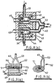
- Fig. 11 shows another modified version of the apparatus of Fig. 7, like parts being labelled by identical reference numerals. This arrangement is used when high humidity levels and dew points up to 100 deg. C. are to be measured.
- the moisture sensors 42, 44 and coiled tube 40 are placed in the warm humid atmosphere to be monitored and the associated sensor circuits 65, 66 are located outside the chamber or duct 90 through which the humid gas sample B flows.
Landscapes
- Physics & Mathematics (AREA)
- Health & Medical Sciences (AREA)
- Life Sciences & Earth Sciences (AREA)
- Chemical & Material Sciences (AREA)
- Analytical Chemistry (AREA)
- Biochemistry (AREA)
- General Health & Medical Sciences (AREA)
- General Physics & Mathematics (AREA)
- Immunology (AREA)
- Pathology (AREA)
- Investigating Or Analyzing Materials Using Thermal Means (AREA)
Claims (36)
- Verfahren zur Messung der Taupunkttemperatur eines feuchten Gases, mit den folgenden Schritten:Leiten eines feuchten Gasstroms (A) über eine Oberfläche (2);Messen der Temperatur der Oberfläche;Anbringen eines Feuchtigkeitssensors (5) in dem Gasstrom stromabwärts von der Oberfläche;Kühlen der Oberfläche, um die Temperatur (T) der Oberfläche fortschreitend zu erniedrigen;während der Kühlung der Oberfläche, Überwachen des Feuchtigkeitsgehalts (M) des Gases stromabwärts von der Oberfläche;Erfassen einer Abnahme des Feuchtigkeitsgehalts des Gases stromabwärts von der Oberfläche wegen einer Kondensation der Feuchtigkeit aus dem feuchten Gas bei dessen Taupunkttemperatur, und Verwendung der erfaßten Abnahme des Feuchtigkeitsgehalts wegen der Feuchtigkeitskondensation zur Steuerung der gemessenen Temperatur, um eine Taupunkttemperatur (TD) zu erhalten.
- Verfahren nach Anspruch 1, wobei die erfaßte Abnahme des Feuchtigkeitsgehalts zur Steuerung der Temperaturmessung der Oberfläche (2) benutzt wird, um eine Taupunkttemperatur (TD) zu erhalten.
- Verfahren nach Anspruch 1 oder Anspruch 2, wobei die erfaßte Abnahme des Feuchtigkeitsgehalts (M) wegen der Feuchtigkeitskondensation zur Steuerung der Kühlung der Oberfläche (2) benutzt wird, um die Oberfläche zumindest während der Zeitspanne der Taupunkttemperaturmessung im wesentlichen auf der Taupunkttemperatur (TD) des feuchten Gases (A) zu halten.
- Verfahren nach Anspruch 1 oder Anspruch 2, wobei man durch Messung der Temperatur der Oberfläche (2) bei Erfassung einer Abnahme des Feuchtigkeitsgehalts (M) wegen Feuchtigkeitskondensation einen Einzelwert für die Taupunkttemperatur (TD) erhält.
- Verfahren nach einem der vorstehenden Ansprüche, wobei die Kühlung der Oberfläche (2) bei Erfassung einer Abnahme des Feuchtigkeitsgehalts (M) wegen Feuchtigkeitskondensation vermindert oder abgebrochen wird.
- Verfahren nach Anspruch 5, wobei nach Verminderung oder Abbruch der Kühlung die Oberfläche (2) extern beheizt wird, um die Temperatur (T) der Oberfläche (2) zu erhöhen.
- Verfahren nach Anspruch 5 oder Anspruch 6, das ferner den Schritt zur Fortsetzung der Überwachung des Feuchtigkeitsgehalts des Gases stromabwärts von der Oberfläche (2) aufweist, wenn der Feuchtigkeitsgehalt (M) wegen Verdunstung kondensierter Feuchtigkeit von der Oberfläche ansteigt, und bis der Feuchtigkeitsgehalt anschließend bis auf einen Endfeuchtigkeitsgehalt (Mc) abnimmt, der im wesentlichen gleich dem Feuchtigkeitsgehalt vor der Abnahme wegen Feuchtigkeitskondensation ist.
- Verfahren nach Anspruch 7, wobei die Kühlung der Oberfläche (2) bei Erfassung des Endfeuchtigkeitsgehalts (Mc) verstärkt oder von neuem begonnen und mindestens so lange fortgesetzt wird, bis eine weitere Abnahme des Feuchtigkeitsgehalts unter den Endfeuchtigkeitsgehalt (Mc) erfaßt wird.
- Verfahren nach Anspruch 8, wobei der Taupunkt (TD) als über einen Feuchtigkeitskondensations- und -verdunstungszyklus gemittelte Temperatur der Oberfläche (2) berechnet wird, wobei der Zyklus als Zeitspanne zwischen dem Beginn der ersten Abnahme des Feuchtigkeitsgehalts und dem Beginn der weiteren Abnahme des Feuchtigkeitsgehalts unter den Endfeuchtigkeitsgehalt (Mc) definiert ist.
- Verfahren nach Anspruch 8, wobei mindestens zwei aufeinanderfolgende Feuchtigkeitskondensations- und -verdunstungszyklen ausgeführt werden, wobei jeder Zyklus mit einer Abnahme des Feuchtigkeitsgehalts wegen Feuchtigkeitskondensation beginnt und die Taupunkttemperatur (TD) als über die zwei oder mehreren aufeinanderfolgenden Zyklen gemittelte Temperatur der Oberfläche (2) berechnet wird.
- Verfahren nach einem der Ansprüche 7 bis 10, wobei die Temperaturänderung der Oberfläche (2) im wesentlichen auf einen Bereich zwischen 0,1°C oberhalb und unterhalb der Taupunkttemperatur (TD) eingeschränkt ist.
- Verfahren nach einem der vorstehenden Ansprüche, das ferner den Schritt zur Überwachung des Feuchtigkeitsgehalts des Gases stromaufwärts von der Oberfläche (2) und zur Überwachung der Differenz zwischen dem Feuchtigkeitsgehalt des Gases stromabwärts von der Oberfläche und dem Feuchtigkeitsgehalt des Gases stromaufwärts von der Oberfläche einschließt.
- Verfahren zur Messung der Taupunkttemperatur mit den folgenden Schritten: Bereitstellen eines Feuchtigkeitssensors (5) und einer Prozessoreinrichtung (60), die so programmiert ist, daß sie das Ausgangssignal des Feuchtigkeitssensors in einen Anzeigewert der Taupunkttemperatur umrechnet, wobei das Verfahren ferner die Eichung der Prozessoreinrichtung durch die folgenden Schritte aufweist: Messen der Taupunkttemperatur (TD) einer Gasprobe unter Anwendung eines Verfahrens gemäß Anspruch 1, um eine Taupunkttemperaturmessung zu erhalten; Vergleich der Taupunkttemperaturmessung mit dem für die Probe erhaltenen Taupunkttemperaturanzeigewert; und Umprogrammieren der Prozessoreinrichtung, falls die Taupunkttemperaturmessung und der Taupunkttemperaturanzeigewert nicht übereinstimmen.
- Verfahren nach Anspruch 13, wobei der Feuchtigkeitssensor (5) ein elektrisches Ausgangssignal liefert, das auf Änderungen der elektrischen Kapazität basiert.
- Vorrichtung zur Messung der Taupunkttemperatur eines feuchten Gases, wobei die Vorrichtung aufweist: eine Oberfläche (2), ein Kühlsystem (3, 51, 56), das so ausgebildet und eingerichtet ist, daß es die Oberfläche kühlt, um die Temperatur (T) der Oberfläche fortschreitend abzusenken, einen Feuchtigkeitssensor (5, 44) zur Überwachung des Feuchtigkeitsgehalts eines über die Oberfläche fließenden Gases (A) stromabwärts von der Oberfläche, eine Detektoreinrichtung (9, 60) zum Erfassen einer Abnahme des überwachten Feuchtigkeitsgehalts (M) des Gases wegen Feuchtigkeitskondensation des feuchten Gases bei dessen Taupunkttemperatur (TD), und eine Temperaturmeßeinrichtung (7, 62) zur Messung der Temperatur der Oberfläche.
- Vorrichtung nach Anspruch 15, die ferner eine Kühlungssteuereinrichtung (6, 9, 60) zur Steuerung der Oberfläche (2) aufweist, um die Oberfläche zumindest während der Zeitspanne der Taupunkttemperaturmessung zur Bestimmung einer Taupunkttemperatur (TD) im wesentlichen auf der Taupunkttemperatur des feuchten Gases (A) zu halten.
- Vorrichtung nach Anspruch 16, wobei die Kühlungssteuereinrichtung eine Rückkopplungsschleife zwischen der Detektoreinrichtung (9) und dem Kühlsystem (3) aufweist und die Detektoreinrichtung so angepaßt ist, daß sie über die Rückkopplungsschleife ein Signal zum Kühlsystem sendet, wenn durch die Detektoreinrichtung (9) eine Abnahme des Feuchtigkeitsgehalts (M) wegen Feuchtigkeitskondensation aus dem feuchten Gas (A) erfaßt wird.
- Vorrichtung nach Anspruch 16 oder Anspruch 17, wobei die Detektoreinrichtung (9) einen PID-Regler aufweist.
- Vorrichtung nach Anspruch 16 oder Anspruch 17, die ferner eine Signalverarbeitungseinrichtung (20, 60) aufweist, die für die Verarbeitung von Temperaturmessungen an der Oberfläche (2) programmiert ist, um während einer Taupunkttemperaturmeßperiode einen Mittelwert der Temperatur (T) der Oberfläche (2) zu berechnen und den Mittelwert als gemessene Taupunkttemperatur (TD) auszugeben.
- Vorrichtung nach Anspruch 19, wobei die Detektoreinrichtung, die Kühlungssteuereinrichtung und die Signalverarbeitungseinrichtung zusammen in Form eines Mikroprozessors (60) bereitgestellt werden.
- Vorrichtung nach Anspruch 17, die ferner eine Heizeinrichtung aufweist, die so ausgebildet und angeordnet ist, daß sie nach Empfang des Signals über den gesunkenen Feuchtigkeitsgehalt von der Detektoreinrichtung (9) die Oberfläche (2) zu beheizen beginnt, um die Temperatur der Oberfläche zu erhöhen.
- Vorrichtung nach einem der Ansprüche 15 bis 21, die ferner einen zweiten Feuchtigkeitssensor (13, 42) zur Überwachung des Feuchtigkeitsgehalts (M) des Gases (A) stromaufwärts von der Oberfläche (2) aufweist.
- Vorrichtung nach Anspruch 22, wobei der zweite Feuchtigkeitssensor (13, 42) vorgeeicht ist, um Direktanzeigewerte der Taupunkttemperatur (TD) eines feuchten Gases (A) zu erhalten.
- Vorrichtung nach Anspruch 22 in dessen Abhängigkeit von Anspruch 19 oder Anspruch 20, wobei die Signalverarbeitungseinrichtung (20, 60) so programmiert ist, daß sie einen von dem zweiten Sensor (13, 42) erhaltenen Taupunktdirektanzeigewert während der Taupunkttemperaturmeßperiode mit dem berechneten Mittelwert der Temperatur (T) der Oberfläche (2) vergleicht und den vorgeeichten zweiten Feuchtigkeitssensor nacheicht, wenn der verglichene Direktanzeigewert und der berechnete Mittelwert nicht übereinstimmen.
- Vorrichtung nach einem der Ansprüche 15 bis 24, wobei der oder jeder Feuchtigkeitssensor (5, 13, 42, 44) von einem Typ mit einer elektrischen Kapazität ist, die mit Änderungen des Feuchtigkeitsgehalts der Atmosphäre variiert, welcher der Sensor ausgesetzt ist.
- Vorrichtung nach einem der Ansprüche 15 bis 25, wobei das Kühlsystem eine thermoelektrische Wärmepumpe (3, 56) mit eingebauten Peltier-Kristallen aufweist.
- Vorrichtung nach Anspruch 26, wobei die Oberfläche (2) eine Schicht aus wärmeleitendem Material aufweist, die sich im Kontakt mit der Wärmepumpe (3) befindet.
- Vorrichtung nach einem der Ansprüche 15 bis 26, wobei die Oberfläche eine Innenfläche eines Teils einer Wand eines Leitungsrohrs (40) aufweist, durch das eine Strömung des feuchten Gases (A) fließen kann.
- Vorrichtung nach Anspruch 28, wobei das Kühlsystem einen Vorratsbehälter mit wärmeleitender Flüssigkeit (51) aufweist, in den ein Abschnitt des Rohrs (40) eintaucht, wobei die Temperatur des flüssigen Kühlmittels durch eine thermoelektrische Temperatursteuereinrichtung (56) gesteuert wird.
- Vorrichtung nach Anspruch 28, wobei das Kühlsystem eine Kammer (70) mit einer verengten Öffnung (72) aufweist, durch die komprimiertes Gas in die Kammer eingeleitet wird, wobei ein Abschnitt des Rohrs (40) in der Kammer angeordnet ist, wodurch die Ausdehnung des komprimierten Gases in die Kammer (70) zu einer Abkühlung des Rohrabschnitts führt.
- Vorrichtung nach Anspruch 30, wobei die Vorrichtung tragbar ist.
- Vorrichtung nach Anspruch 19 oder Anspruch 20, die eine zusätzliche Temperaturmerßeinrichtung (92) aufweist, deren Anzeigewerte durch die Signalverarbeitungseinrichtung (20, 60) genutzt werden, um von der Vorrichtung erhaltene Taupunkttemperaturanzeigewerte als relative Luftfeuchtigkeit auszudrücken.
- Vorrichtung nach Anspruch 22 in dessen Abhängigkeit von Anspruch 19 oder Anspruch 20, wobei die Signalverarbeitungseinrichtung (20, 60) so programmiert ist, daß sie mindestens einen der Feuchtigkeitssensoren (5, 13, 42, 44) voreicht, um momentane Taupunkttemperaturwerte für gemessene Anzeigewerte des Feuchtigkeitsgehalts anzugeben.
- Vorrichtung nach Anspruch 33, wobei die Signalverarbeitungseinrichtung (20, 60) so programmiert ist, daß sie beide Feuchtigkeitssensorn (5, 13, 42, 44) voreicht, um einen etwaigen Ausfall des einen oder des anderen Feuchtigkeitssensors zu erkennen und anschließend Taupunkttemperaturanzeigewerte anzuzeigen, die von dem anderen, funktionstüchtigen vorgeeichten Feuchtigkeitssensor gewonnen werden.
- Vorrichtung nach Anspruch 23 in dessen Abhängigkeit von Anspruch 19 oder 20, wobei die Signalverarbeitungseinrichtung (20, 60) so programmiert ist, daß bei Ausfall der Temperaturmerßeinrichtung (7, 62) oder des Kühlsystems (3, 51, 56) die Vorrichtung weiter arbeitet, indem sie Taupunktanzeigewerte anzeigt, die von dem vorgeeichten zweiten Feuchtigkeitssensor (13, 42) gewonnen werden.
- Vorrichtung nach einem der Ansprüche 22 bis 35 in deren Abhängigkeit von Anspruch 19 oder Anspruch 20, wobei die Signalverarbeitungseinrichtung (20, 60) so programmiert ist, daß sie die Nutzungsdauer mindestens eines der Feuchtigkeitssensoren (5, 13, 42, 44) auf der Basis von Anzeigewerten abschätzt, die davon während des Betriebs der Vorrichtung abgelesen werden.
Applications Claiming Priority (3)
| Application Number | Priority Date | Filing Date | Title |
|---|---|---|---|
| GB9511204 | 1995-06-02 | ||
| GBGB9511204.1A GB9511204D0 (en) | 1995-06-02 | 1995-06-02 | Method and apparatus for measuring dew point temperature of a moist gas |
| PCT/GB1996/001283 WO1996038723A1 (en) | 1995-06-02 | 1996-05-31 | Method and apparatus for measuring dew point temperature of a moist gas |
Publications (2)
| Publication Number | Publication Date |
|---|---|
| EP0829008A1 EP0829008A1 (de) | 1998-03-18 |
| EP0829008B1 true EP0829008B1 (de) | 2002-07-31 |
Family
ID=10775426
Family Applications (1)
| Application Number | Title | Priority Date | Filing Date |
|---|---|---|---|
| EP96919929A Expired - Lifetime EP0829008B1 (de) | 1995-06-02 | 1996-05-31 | Verfahren und vorrichtung zur taupunkttemperaturmessung eines feuchten gases |
Country Status (8)
| Country | Link |
|---|---|
| US (1) | US6022138A (de) |
| EP (1) | EP0829008B1 (de) |
| JP (1) | JP3632100B2 (de) |
| AU (1) | AU5829296A (de) |
| DE (1) | DE69622712T2 (de) |
| ES (1) | ES2179944T3 (de) |
| GB (1) | GB9511204D0 (de) |
| WO (1) | WO1996038723A1 (de) |
Cited By (2)
| Publication number | Priority date | Publication date | Assignee | Title |
|---|---|---|---|---|
| WO2005075980A1 (de) | 2004-02-03 | 2005-08-18 | CiS Institut für Mikrosensorik gGmbH | Verfahren und anordnung zur bestimmung der parameter eines prozessmediums |
| EP4249903A4 (de) * | 2020-11-17 | 2024-07-24 | Klimov, Andrei Aleksandrovich | Verfahren und vorrichtung zur taupunktmessung |
Families Citing this family (27)
| Publication number | Priority date | Publication date | Assignee | Title |
|---|---|---|---|---|
| JP3485796B2 (ja) | 1998-05-12 | 2004-01-13 | サンポット株式会社 | 降雪センサー |
| IL126826A0 (en) * | 1998-10-30 | 1999-08-17 | Optiguide Ltd | Optical hygrometers |
| US6926439B2 (en) | 1998-10-30 | 2005-08-09 | Optiguide Ltd. | Dew point hygrometers and dew sensors |
| EP1417477A1 (de) * | 2001-08-03 | 2004-05-12 | General Eastern Instruments, Inc. | Abbildungsgerät für die gasanalyse |
| NL1023791C2 (nl) * | 2003-07-01 | 2005-01-04 | Lely Entpr Ag | Melkinstallatie. |
| ITMI20040249A1 (it) * | 2004-02-16 | 2004-05-16 | Consiglio Nazionale Ricerche | Rilevatore di condensa e metodo per rilevazione di condensa su una superficie |
| US7059170B2 (en) | 2004-02-27 | 2006-06-13 | Nielsen-Kellerman, Inc. | Method and apparatus for measuring relative humidity of a mixture |
| US7168850B2 (en) * | 2004-03-30 | 2007-01-30 | Yamatake Corporation | Mirror surface state detection device and moisture detection device |
| JP4504318B2 (ja) * | 2006-01-20 | 2010-07-14 | 株式会社山武 | 鏡面冷却式露点計 |
| JP4523567B2 (ja) * | 2006-04-17 | 2010-08-11 | エスペック株式会社 | 露点計 |
| DE102006024515A1 (de) * | 2006-05-23 | 2007-11-29 | Bayer Materialscience Ag | Verfahren zur Chlorwasserstoff-Oxidation mit Sauerstoff |
| US8292497B2 (en) * | 2008-07-16 | 2012-10-23 | GM Global Technology Operations LLC | Cloud point monitoring systems for determining a cloud point temperature of diesel fuel |
| US10101219B2 (en) | 2008-09-05 | 2018-10-16 | The Research Foundation For The State University Of New York | Carbon nanotube sensing system, carbon nanotube dew point hygrometer, method of use thereof and method of forming a carbon nanotube dew point hygrometer |
| WO2011111178A1 (ja) * | 2010-03-10 | 2011-09-15 | 富士通株式会社 | 環境測定システム及び環境測定方法 |
| JP2012175086A (ja) * | 2011-02-24 | 2012-09-10 | Fujitsu Ltd | 結露検知装置、電子機器冷却システム、及び結露検出方法 |
| US9395252B1 (en) * | 2012-02-06 | 2016-07-19 | Dynamic Ratings Pty Ltd. | Method of estimating internal dielectric fluid temperature of an electrical device |
| US20180180224A1 (en) * | 2015-06-18 | 2018-06-28 | Pringle Beleski And Associates Limited | System and method for gas management |
| GB201521199D0 (en) * | 2015-12-01 | 2016-01-13 | Norwegian Inst For Air Res | Air monitoring |
| WO2017213118A1 (ja) * | 2016-06-08 | 2017-12-14 | 国立研究開発法人物質・材料研究機構 | 露点測定方法及び露点測定装置 |
| US10819719B2 (en) * | 2016-10-11 | 2020-10-27 | General Electric Company | Systems and methods for protecting a physical asset against a threat |
| US11236865B2 (en) * | 2018-01-29 | 2022-02-01 | Cryovation, Llc. | Automatic detection of moisture in compressed gas cylinder |
| CN111458374B (zh) * | 2019-01-18 | 2023-10-24 | 上海沃尔沃汽车研发有限公司 | 稀释通道内水凝结监测系统和用于车辆排放测试的方法 |
| CN111855744B (zh) * | 2020-08-24 | 2025-04-04 | 国鸿氢能科技(嘉兴)股份有限公司 | 一种露点测试装置及露点测试方法 |
| EP4155719B1 (de) * | 2021-09-28 | 2026-03-18 | Abb Schweiz Ag | Verfahren zur feuchtemessung |
| CN114533037B (zh) * | 2022-02-23 | 2022-11-22 | 安徽省立医院(中国科学技术大学附属第一医院) | 一种基于儿童呼吸气体的疾病检测系统及方法 |
| CN115200748B (zh) * | 2022-09-15 | 2022-12-02 | 深圳市景新浩科技有限公司 | 基于智能电子体温计状态测量控制系统 |
| CN120992727A (zh) * | 2025-10-22 | 2025-11-21 | 广东海洋大学 | 一种基于便携式水汽提取装置的空气水蒸气氢氧同位素分析方法 |
Family Cites Families (11)
| Publication number | Priority date | Publication date | Assignee | Title |
|---|---|---|---|---|
| US2106593A (en) * | 1936-05-05 | 1938-01-25 | Socony Vacuum Oil Co Inc | Apparatus for determining the dew point of a vapor product |
| US3177716A (en) * | 1961-03-14 | 1965-04-13 | Basic Products Corp | Instrument for determining dew-point |
| FR2231287A5 (de) * | 1973-05-23 | 1974-12-20 | Solvay | |
| GB1541441A (en) * | 1975-06-18 | 1979-02-28 | Land Pyrometers Ltd | Dew pont meters |
| DE2634274A1 (de) * | 1976-07-30 | 1978-02-02 | Detlef Mann | Taupunkt-messgeraet |
| GB2043908A (en) * | 1979-03-09 | 1980-10-08 | Moisture Control & Mesurement | Humidity Sensor Element |
| US4579462A (en) * | 1985-05-20 | 1986-04-01 | Trans-Met Engineering, Inc. | Dew point measuring apparatus |
| DE4023796C1 (de) * | 1990-07-26 | 1991-11-14 | M. Laumen Thermotechnik Gmbh, 4150 Krefeld, De | |
| US5165793A (en) * | 1991-10-11 | 1992-11-24 | Lustron Corporation | Dew point measuring method and apparatus |
| GB9225425D0 (en) * | 1992-12-04 | 1993-01-27 | Protimeter Plc | Humidity measuring instrument |
| US5364185A (en) * | 1993-04-16 | 1994-11-15 | California Institute Of Technology | High performance miniature hygrometer and method thereof |
-
1995
- 1995-06-02 GB GBGB9511204.1A patent/GB9511204D0/en active Pending
-
1996
- 1996-05-31 ES ES96919929T patent/ES2179944T3/es not_active Expired - Lifetime
- 1996-05-31 DE DE69622712T patent/DE69622712T2/de not_active Expired - Fee Related
- 1996-05-31 JP JP53629496A patent/JP3632100B2/ja not_active Expired - Fee Related
- 1996-05-31 WO PCT/GB1996/001283 patent/WO1996038723A1/en not_active Ceased
- 1996-05-31 AU AU58292/96A patent/AU5829296A/en not_active Abandoned
- 1996-05-31 US US08/973,457 patent/US6022138A/en not_active Expired - Fee Related
- 1996-05-31 EP EP96919929A patent/EP0829008B1/de not_active Expired - Lifetime
Cited By (3)
| Publication number | Priority date | Publication date | Assignee | Title |
|---|---|---|---|---|
| WO2005075980A1 (de) | 2004-02-03 | 2005-08-18 | CiS Institut für Mikrosensorik gGmbH | Verfahren und anordnung zur bestimmung der parameter eines prozessmediums |
| DE102004005353B4 (de) * | 2004-02-03 | 2016-08-11 | CiS Forschungsinstitut für Mikrosensorik GmbH | Verfahren zur Bestimmung der Parameter von Gasen |
| EP4249903A4 (de) * | 2020-11-17 | 2024-07-24 | Klimov, Andrei Aleksandrovich | Verfahren und vorrichtung zur taupunktmessung |
Also Published As
| Publication number | Publication date |
|---|---|
| JP3632100B2 (ja) | 2005-03-23 |
| DE69622712D1 (de) | 2002-09-05 |
| AU5829296A (en) | 1996-12-18 |
| JPH11511242A (ja) | 1999-09-28 |
| WO1996038723A1 (en) | 1996-12-05 |
| US6022138A (en) | 2000-02-08 |
| EP0829008A1 (de) | 1998-03-18 |
| ES2179944T3 (es) | 2003-02-01 |
| GB9511204D0 (en) | 1995-07-26 |
| DE69622712T2 (de) | 2003-03-13 |
Similar Documents
| Publication | Publication Date | Title |
|---|---|---|
| EP0829008B1 (de) | Verfahren und vorrichtung zur taupunkttemperaturmessung eines feuchten gases | |
| US8851745B2 (en) | Hygrometer and dew-point instrument | |
| US7360416B2 (en) | Non-contact condensation detecting apparatus | |
| US5299867A (en) | Low moisture cryogenic hygrometer | |
| US6575621B1 (en) | Dew point hygrometers and dew sensors | |
| US6509553B2 (en) | Method and apparatus for providing an indication of the composition of a fluid particularly useful in heat pumps and vaporizers | |
| US11454603B2 (en) | Dew point measuring method and dew point measuring device | |
| Burgass et al. | Development of a new method for measurement of the water dew/frost point of gas | |
| US5971609A (en) | Method of measuring the dew point or frost point of a gas having low water content | |
| US5148710A (en) | Method and apparatus for determining the relative humidity of gaseous materials | |
| US5165793A (en) | Dew point measuring method and apparatus | |
| US20040042526A1 (en) | Dew point hygrometers and dew sensors | |
| US7393135B2 (en) | Moisture detection device | |
| EP0205196B1 (de) | Vorrichtung zur Erfassung von kondensierbaren Komponenten in einem Gasstrom | |
| EP0617271B1 (de) | Verfahren zur gleichzeitigen Messung der Wärmeleitfähigkeit und kinematischen Viskosität | |
| WO1998039649A1 (en) | Reactive gas sampling/analyzing hygrometry system | |
| RU2117278C1 (ru) | Гигрометр | |
| Roberts | Dew point temperature | |
| US20240151668A1 (en) | Device and Method for Determining Dewpoint or Humidity | |
| CA2066765A1 (en) | Process and device for determining the dew point of components of a gas mixture | |
| CA1073976A (en) | Dewpointmeters | |
| BRODGESELL et al. | 8.32 Moisture in Air: Humidity and Dew Point | |
| CA1301477C (en) | Chilled piezoelectric hygrometer | |
| RU2316759C2 (ru) | Измеритель влажности | |
| Buck et al. | A Cryogenic, Low-PPB Range Moisture Analyzer for Process Gases |
Legal Events
| Date | Code | Title | Description |
|---|---|---|---|
| PUAI | Public reference made under article 153(3) epc to a published international application that has entered the european phase |
Free format text: ORIGINAL CODE: 0009012 |
|
| 17P | Request for examination filed |
Effective date: 19971216 |
|
| AK | Designated contracting states |
Kind code of ref document: A1 Designated state(s): BE CH DE ES FR GB IE IT LI NL |
|
| 17Q | First examination report despatched |
Effective date: 20000720 |
|
| GRAG | Despatch of communication of intention to grant |
Free format text: ORIGINAL CODE: EPIDOS AGRA |
|
| GRAG | Despatch of communication of intention to grant |
Free format text: ORIGINAL CODE: EPIDOS AGRA |
|
| GRAH | Despatch of communication of intention to grant a patent |
Free format text: ORIGINAL CODE: EPIDOS IGRA |
|
| GRAH | Despatch of communication of intention to grant a patent |
Free format text: ORIGINAL CODE: EPIDOS IGRA |
|
| GRAH | Despatch of communication of intention to grant a patent |
Free format text: ORIGINAL CODE: EPIDOS IGRA |
|
| GRAA | (expected) grant |
Free format text: ORIGINAL CODE: 0009210 |
|
| AK | Designated contracting states |
Kind code of ref document: B1 Designated state(s): BE CH DE ES FR GB IE IT LI NL |
|
| REG | Reference to a national code |
Ref country code: GB Ref legal event code: FG4D Ref country code: CH Ref legal event code: EP |
|
| REG | Reference to a national code |
Ref country code: IE Ref legal event code: FG4D |
|
| REF | Corresponds to: |
Ref document number: 69622712 Country of ref document: DE Date of ref document: 20020905 |
|
| REG | Reference to a national code |
Ref country code: CH Ref legal event code: NV Representative=s name: RITSCHER & PARTNER AG PATENTANWAELTE |
|
| ET | Fr: translation filed | ||
| REG | Reference to a national code |
Ref country code: ES Ref legal event code: FG2A Ref document number: 2179944 Country of ref document: ES Kind code of ref document: T3 |
|
| PLBE | No opposition filed within time limit |
Free format text: ORIGINAL CODE: 0009261 |
|
| STAA | Information on the status of an ep patent application or granted ep patent |
Free format text: STATUS: NO OPPOSITION FILED WITHIN TIME LIMIT |
|
| 26N | No opposition filed |
Effective date: 20030506 |
|
| PGFP | Annual fee paid to national office [announced via postgrant information from national office to epo] |
Ref country code: IE Payment date: 20050511 Year of fee payment: 10 |
|
| PGFP | Annual fee paid to national office [announced via postgrant information from national office to epo] |
Ref country code: CH Payment date: 20050527 Year of fee payment: 10 |
|
| PGFP | Annual fee paid to national office [announced via postgrant information from national office to epo] |
Ref country code: ES Payment date: 20050624 Year of fee payment: 10 |
|
| PGFP | Annual fee paid to national office [announced via postgrant information from national office to epo] |
Ref country code: BE Payment date: 20050715 Year of fee payment: 10 |
|
| PG25 | Lapsed in a contracting state [announced via postgrant information from national office to epo] |
Ref country code: LI Free format text: LAPSE BECAUSE OF NON-PAYMENT OF DUE FEES Effective date: 20060531 Ref country code: IE Free format text: LAPSE BECAUSE OF NON-PAYMENT OF DUE FEES Effective date: 20060531 Ref country code: CH Free format text: LAPSE BECAUSE OF NON-PAYMENT OF DUE FEES Effective date: 20060531 Ref country code: BE Free format text: LAPSE BECAUSE OF NON-PAYMENT OF DUE FEES Effective date: 20060531 |
|
| PGFP | Annual fee paid to national office [announced via postgrant information from national office to epo] |
Ref country code: IT Payment date: 20060531 Year of fee payment: 11 |
|
| PG25 | Lapsed in a contracting state [announced via postgrant information from national office to epo] |
Ref country code: ES Free format text: LAPSE BECAUSE OF NON-PAYMENT OF DUE FEES Effective date: 20060601 |
|
| REG | Reference to a national code |
Ref country code: CH Ref legal event code: PL |
|
| REG | Reference to a national code |
Ref country code: IE Ref legal event code: MM4A |
|
| PGFP | Annual fee paid to national office [announced via postgrant information from national office to epo] |
Ref country code: DE Payment date: 20070524 Year of fee payment: 12 |
|
| REG | Reference to a national code |
Ref country code: ES Ref legal event code: FD2A Effective date: 20060601 |
|
| BERE | Be: lapsed |
Owner name: *SONANDER SVEN OLOF Effective date: 20060531 |
|
| PGFP | Annual fee paid to national office [announced via postgrant information from national office to epo] |
Ref country code: NL Payment date: 20080501 Year of fee payment: 13 |
|
| PGFP | Annual fee paid to national office [announced via postgrant information from national office to epo] |
Ref country code: GB Payment date: 20080604 Year of fee payment: 13 |
|
| PG25 | Lapsed in a contracting state [announced via postgrant information from national office to epo] |
Ref country code: DE Free format text: LAPSE BECAUSE OF NON-PAYMENT OF DUE FEES Effective date: 20081202 |
|
| PG25 | Lapsed in a contracting state [announced via postgrant information from national office to epo] |
Ref country code: IT Free format text: LAPSE BECAUSE OF NON-PAYMENT OF DUE FEES Effective date: 20070531 |
|
| GBPC | Gb: european patent ceased through non-payment of renewal fee |
Effective date: 20090531 |
|
| NLV4 | Nl: lapsed or anulled due to non-payment of the annual fee |
Effective date: 20091201 |
|
| PG25 | Lapsed in a contracting state [announced via postgrant information from national office to epo] |
Ref country code: NL Free format text: LAPSE BECAUSE OF NON-PAYMENT OF DUE FEES Effective date: 20091201 |
|
| REG | Reference to a national code |
Ref country code: FR Ref legal event code: ST Effective date: 20100129 |
|
| PG25 | Lapsed in a contracting state [announced via postgrant information from national office to epo] |
Ref country code: FR Free format text: LAPSE BECAUSE OF NON-PAYMENT OF DUE FEES Effective date: 20090602 |
|
| PGFP | Annual fee paid to national office [announced via postgrant information from national office to epo] |
Ref country code: FR Payment date: 20080514 Year of fee payment: 13 |
|
| PG25 | Lapsed in a contracting state [announced via postgrant information from national office to epo] |
Ref country code: GB Free format text: LAPSE BECAUSE OF NON-PAYMENT OF DUE FEES Effective date: 20090531 |