EP0829096B1 - Metallhalogenidlampe - Google Patents
Metallhalogenidlampe Download PDFInfo
- Publication number
- EP0829096B1 EP0829096B1 EP97901236A EP97901236A EP0829096B1 EP 0829096 B1 EP0829096 B1 EP 0829096B1 EP 97901236 A EP97901236 A EP 97901236A EP 97901236 A EP97901236 A EP 97901236A EP 0829096 B1 EP0829096 B1 EP 0829096B1
- Authority
- EP
- European Patent Office
- Prior art keywords
- lamp
- discharge vessel
- filling pressure
- mbar
- discharge
- Prior art date
- Legal status (The legal status is an assumption and is not a legal conclusion. Google has not performed a legal analysis and makes no representation as to the accuracy of the status listed.)
- Expired - Lifetime
Links
- 229910001507 metal halide Inorganic materials 0.000 title claims description 4
- 150000005309 metal halides Chemical class 0.000 title claims description 4
- 239000000919 ceramic Substances 0.000 claims description 18
- 150000004820 halides Chemical class 0.000 claims description 5
- 229910052753 mercury Inorganic materials 0.000 claims description 3
- QSHDDOUJBYECFT-UHFFFAOYSA-N mercury Chemical compound [Hg] QSHDDOUJBYECFT-UHFFFAOYSA-N 0.000 claims description 2
- 239000004020 conductor Substances 0.000 description 14
- PNEYBMLMFCGWSK-UHFFFAOYSA-N aluminium oxide Inorganic materials [O-2].[O-2].[O-2].[Al+3].[Al+3] PNEYBMLMFCGWSK-UHFFFAOYSA-N 0.000 description 4
- 239000011195 cermet Substances 0.000 description 3
- 238000010276 construction Methods 0.000 description 3
- 229910052593 corundum Inorganic materials 0.000 description 3
- 229910001845 yogo sapphire Inorganic materials 0.000 description 3
- 238000010891 electric arc Methods 0.000 description 2
- 238000004519 manufacturing process Methods 0.000 description 2
- 239000000463 material Substances 0.000 description 2
- 229910052751 metal Inorganic materials 0.000 description 2
- 239000002184 metal Substances 0.000 description 2
- 229910044991 metal oxide Inorganic materials 0.000 description 2
- 150000004706 metal oxides Chemical class 0.000 description 2
- 238000009877 rendering Methods 0.000 description 2
- 230000000694 effects Effects 0.000 description 1
- 230000002349 favourable effect Effects 0.000 description 1
- 238000009434 installation Methods 0.000 description 1
- 150000004767 nitrides Chemical class 0.000 description 1
- 230000001737 promoting effect Effects 0.000 description 1
- 229910052594 sapphire Inorganic materials 0.000 description 1
- 239000010980 sapphire Substances 0.000 description 1
Images
Classifications
-
- H—ELECTRICITY
- H01—ELECTRIC ELEMENTS
- H01J—ELECTRIC DISCHARGE TUBES OR DISCHARGE LAMPS
- H01J61/00—Gas-discharge or vapour-discharge lamps
- H01J61/02—Details
- H01J61/30—Vessels; Containers
- H01J61/34—Double-wall vessels or containers
-
- H—ELECTRICITY
- H01—ELECTRIC ELEMENTS
- H01J—ELECTRIC DISCHARGE TUBES OR DISCHARGE LAMPS
- H01J61/00—Gas-discharge or vapour-discharge lamps
- H01J61/02—Details
- H01J61/12—Selection of substances for gas fillings; Specified operating pressure or temperature
- H01J61/125—Selection of substances for gas fillings; Specified operating pressure or temperature having an halogenide as principal component
Definitions
- the invention relates to a metal halide lamp provided with an outer bulb having a volume V bu in which a discharge vessel with a volume V ob and having a ceramic wall is arranged, which vessel comprises mercury, at least one halide, and also Ar a rare gas having a filling pressure P ob .
- a lamp of the kind mentioned in the opening paragraph is known from WO 95/28732.
- the known lamp which combines a high luminous efficacy with good color properties (among them general color rendering index R a ⁇ 80), is highly suitable for use as a light source for inter alia interior lighting, also because of its comparatively small dimensions.
- ceramic wall in the present description and claims is understood to cover monocrystalline metal oxide (for example, sapphire), densely sintered polycrystalline metal oxide (for example, Al 2 O 3 , YAG) as well as polycrystalline densely sintered metal nitride (for example, AlN).
- filling pressure is understood in the present specification the pressure at room temperature.
- a possible effect occurring at the end of life of the known lamp is a strong direct current which gives rise to damage of the electric installation with which the lamp is operated. This forms a problem which the invention aims to solve.
- a lamp of the kind mentioned in the opening paragraph is for this purpose characterized in that the filling pressure of the Ar satisfies the relation V ob *P ob /V bu ⁇ 6 mbar, with P ob in mbar and V ob and V bu both in mm 3 .
- An important advantage of the lamp according to the invention is that the rare gas pressure in the outer bulb is strongly limited at least in the case of leakage of the discharge vessel.
- the risk of an arc discharge occurring in the outer bulb, and the accompanying occurrence of a strong direct current, is substantially counteracted thereby.
- Leaks of the discharge vessel are found to be the cause of the end of lamp life in many cases.
- the filling pressure of the rare gas is now preferably chosen to be such that the pressure of the rare gas in the case of a leaking discharge vessel is at most 6 mbar.
- the glow discharge is accompanied by a very weak current, which is a favorable property. This is in particular true in case of an a.c. voltage supply of at most 250V or switch mode power supply providing a voltage level at most equal to the top voltage of said a.c. supply.
- the ignition properties of the lamp are not substantially influenced in comparison with the known lamp.
- the rare gas is added because of its ignition-promoting influence, which in general increases with an increasing filling pressure.
- a filling pressure of 40 mbar or less was found to be insufficient for effectively promoting the ignition.
- the rated lamp power is usually comparatively low, in practice preferably at most 150 W.
- Particularly suitable for practical applications are lamps with rated powers of inter alia 100W,70 W, 50 W, and 35 W, and possibly lower.
- the lamps may have a tubular shape or may be provided with reflectorized bulbs.
- the high compactness of the discharge vessel renders the lamp highly suitable for use as a light source for making a light beam.
- a requirement for this is, however, that the outer bulb should have a similar compactness, which again results in the situation that current conductors to the discharge vessel are at a comparatively small distance from one another, especially in the case of a reflectorized bulb and a single-ended tubular bulb.
- a small distance between current conductors is generally conducive to the generation of a discharge.
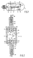
- Fig. 1 shows a high-pressure discharge lamp provided with a discharge vessel 3 with a volume V ob and having a ceramic wall which encloses a discharge space 11.
- the discharge vessel contains a filling which comprises Hg and at least one metal halide, as well as a rare gas having a filling pressure P ob .
- the discharge vessel is closed at one side with a projecting ceramic plug 34, 35 which narrowly surrounds a current lead-through conductor (Fig. 2: 40, 41, 50, 51) to an electrode 4, 5 arranged in the discharge vessel and is connected thereto in a gas-tight manner by means of a melting-ceramic seal (Fig. 2: 10) at an end facing away from the discharge space.
- the discharge vessel is positioned in an outer bulb 1 having a volume V bu and which is provided with a lamp cap 2 at one end.
- a discharge extends between electrodes 4, 5 when the lamp is in the operational state.
- Electrode 4 is connected to a first electrical contact forming part of the lamp cap 2 via a current conductor 8.
- Electrode 5 is connected to a second electrical contact forming part of the lamp cap 2 via a current conductor 9.
- the discharge vessel which is shown in more detail in Fig. 2 (not true to scale), has a ceramic wall and is formed from a cylindrical part with an internal diameter ID bounded on either side by end wall portions 32a, 32b, each end wall portion 32a, 32b defining an end surface 33a, 33b of the discharge space.
- the end wall portions each have an opening in which a projecting ceramic plug 34, 35 is fastened in a gas-tight manner in the end wall portion 32a, 32b by means of a sintered joint S.
- the projecting ceramic plugs 34, 35 each narrowly enclose a current lead-through conductor 40, 41, 50, 51 of a relevant electrode 4, 5 having a tip 4b, 5b.
- the current lead-through conductor is connected in a gas-tight manner to the projecting ceramic plug 34, 35 by means of a melting-ceramic seal 10 at the side facing away from the discharge space.
- the electrode tips 4b, 5b have an interspacing EA.
- the current lead-through conductors each comprise a halide-resistant portion 41, 51, for example in the form of a Mo-Al 2 O 3 cermet and a portion 40, 50 which is fastened to a relevant end plug 34, 35 in a gas-tight manner by means of the melting-ceramic seal 10.
- the melting-ceramic seal extends over a certain distance, for example approximately 1 mm, over the respective Mo-cermet 41, 51.
- the portions 41, 51 may be formed in a manner other than by a Mo-Al 2 O 3 cermet.
- Other possible constructions are known from, for example, EP-0 587 238.
- a particularly suitable construction was found to be inter alia one comprising a halide-resistant coil provided around a similarly resistant pin.
- the portions 40, 50 comprise a metal whose coefficient of expansion corresponds very well to that of the end plugs. Nb, for example, is a very suitable material.
- the portions 40, 50 are connected to the current conductors 8, 9 in a manner not shown in any detail. The lead-through construction described renders it possible to operate the lamp in any burning position.
- Each of the electrodes 4, 5 consists of an electrode rod 4a, 5a provided with a coil 4c, 5c near the tip 4b, 5b.
- the electrode tips in the embodiment described lie substantially in the end surfaces 33a, 33b formed by the end wall portions.
- the projecting ceramic plugs are provided so as to be recessed over a distance a relative to the end wall portions 32a and 32b and are fastened therein in a gas-tight manner by means of a sintered joint S.
- the projecting ceramic plugs 34, 35 are not recessed relative to the end wall portions 32a and 32b. In that case the electrode tips lie between the end surfaces 33a, 33b formed by the end wall portions.
- the rating of the lamp was 70 W, 240V.
- the filling of the discharge vessel comprises 4.4 mg Hg and 8 mg NaI, TlI and (Dy+Ho+Tm)I 3 in a mass ratio of 65:10:25.
- the lamp in addition comprises Ar as an ignition gas with a filling pressure P ob of 160 mbar.
- the lamp was designed for a color temperature of 3000 K with color point coordinates (x, y; 437, 404) and a general color-rendering index Ra of more than 80.
- the discharge vessel is made of polycrystalline alumina, has an internal diameter ID of 6.85 mm and a distance between the electrode tips EA of 7 mm.
- the projecting plugs are sintered in the end wall portions at a distance a of 1 mm from the end surfaces formed by the end wall portions.
- the end wall portions each have a height of 3 mm, so that the sintered joint with the end plugs extends over a length of 2 mm.
- Such a length of the sintered joint is found to be sufficient in practice for realizing a sufficiently strong and gas-tight fastening between the end wall portion and the projecting plug, also in the case of large-scale mass production.
- the electrode tips lie in the end faces.
- the electrodes each comprise a W rod provided with a W coil at the tip.
- the melting-ceramic seal 10 extends over a length of 3 to 3,5 mm of the end of the projecting plug facing away from the discharge space.
- the discharge vessel has a volume V ob of 257 mm 3 .
- the volume V bu of the outer bulb is 12.8 cm 3 .
- the smallest interspacing between the current conductors 8 and 9 is 3 mm.
- the relation P ob *V ob /V bu has in this case a value of 3.2 thus satisfying the requirement ⁇ 6.
- the smallest distance between the current conductors is 3 mm and the volume of the bulb V bu 6.23 cm 3 .
- the rare gas filling pressure P ob in this practical case is 95 mbar and the relation is 3.9.
- the volume of the discharge vessel of a practical lamp with a rating of 35 W, 240V is 117 mm 3 .
- the volume of the outer bulb is 5,71 cm 3 when a reflector bulb of the PAR 20 type is used.
- the smallest interspacing between the current conductors is 3 mm.
- the rare gas filling pressure P ob is chosen to be 200 mbar for this lamp resulting in a value of 4 for the relation P ob *V ob /V bu .
- the rare gas filling pressure in a further practical lamp is 60 mbar, here with a power rating of 150 W and with a tubular outer bulb of the 70 W lamp type.
- the discharge vessel of this lamp has a volume V ob of 930 mm 3 resulting in a value for the relation of 4.4.
Landscapes
- Discharge Lamps And Accessories Thereof (AREA)
- Vessels And Coating Films For Discharge Lamps (AREA)
- Discharge Lamp (AREA)
Claims (3)
- Halogenmetalldampflampe, versehen mit einem Außenkolben, der ein Volumen Vbu hat, in dem ein Entladungsgefäß mit einem Volumen Vob und einer Keramikwandung angeordnet ist, welches Gefäß Quecksilber, zumindest ein Halogenid und auch Ar als Edelgas, das einen Fülldruck Pob hat, umfasst, dadurch gekennzeichnet, dass der Fülldruck des Ar die Beziehung
- Lampe nach Anspruch 1, dadurch gekennzeichnet, dass der Fülldruck des Ar, Pob, so weit begrenzt ist, dass er einem Druck in dem Außenkolben von höchstens 4 mbar entspricht.
- Lampe nach Anspruch 1 oder 2, dadurch gekennzeichnet, dass die Lampe eine Nennleistung von höchstens 150 W hat.
Priority Applications (1)
| Application Number | Priority Date | Filing Date | Title |
|---|---|---|---|
| EP97901236A EP0829096B1 (de) | 1996-02-28 | 1997-02-13 | Metallhalogenidlampe |
Applications Claiming Priority (4)
| Application Number | Priority Date | Filing Date | Title |
|---|---|---|---|
| EP96200522 | 1996-02-28 | ||
| EP96200522 | 1996-02-28 | ||
| PCT/IB1997/000115 WO1997032334A1 (en) | 1996-02-28 | 1997-02-13 | Metal halide lamp |
| EP97901236A EP0829096B1 (de) | 1996-02-28 | 1997-02-13 | Metallhalogenidlampe |
Publications (2)
| Publication Number | Publication Date |
|---|---|
| EP0829096A1 EP0829096A1 (de) | 1998-03-18 |
| EP0829096B1 true EP0829096B1 (de) | 2005-04-20 |
Family
ID=8223728
Family Applications (1)
| Application Number | Title | Priority Date | Filing Date |
|---|---|---|---|
| EP97901236A Expired - Lifetime EP0829096B1 (de) | 1996-02-28 | 1997-02-13 | Metallhalogenidlampe |
Country Status (5)
| Country | Link |
|---|---|
| US (1) | US5808398A (de) |
| EP (1) | EP0829096B1 (de) |
| JP (1) | JPH11504757A (de) |
| DE (1) | DE69733049T2 (de) |
| WO (1) | WO1997032334A1 (de) |
Families Citing this family (11)
| Publication number | Priority date | Publication date | Assignee | Title |
|---|---|---|---|---|
| US6414436B1 (en) * | 1999-02-01 | 2002-07-02 | Gem Lighting Llc | Sapphire high intensity discharge projector lamp |
| US6027515A (en) * | 1999-03-02 | 2000-02-22 | Sound Surgical Technologies Llc | Pulsed ultrasonic device and method |
| DE10028089B4 (de) * | 1999-06-10 | 2010-12-09 | Toshiba Lighting & Technology Corp. | Beleuchtungseinrichtung mit einer Hochleistungs-Entladungslampe |
| US6724144B2 (en) * | 2000-03-21 | 2004-04-20 | Japan Storage Battery Co., Ltd. | Discharge lamp |
| DE202006002833U1 (de) * | 2006-02-22 | 2006-05-04 | Patent-Treuhand-Gesellschaft für elektrische Glühlampen mbH | Hochdruckentladungslampe mit keramischem Entladungsgefäß |
| US7910494B2 (en) * | 2006-03-29 | 2011-03-22 | Tokyo Electron Limited | Thermal processing furnace, gas delivery system therefor, and methods for delivering a process gas thereto |
| US7635655B2 (en) * | 2006-03-30 | 2009-12-22 | Tokyo Electron Limited | Method for replacing a nitrous oxide based oxidation process with a nitric oxide based oxidation process for substrate processing |
| US7534731B2 (en) * | 2007-03-30 | 2009-05-19 | Tokyo Electron Limited | Method for growing a thin oxynitride film on a substrate |
| US20090035463A1 (en) * | 2007-08-03 | 2009-02-05 | Tokyo Electron Limited | Thermal processing system and method for forming an oxide layer on substrates |
| US7659214B2 (en) | 2007-09-30 | 2010-02-09 | Tokyo Electron Limited | Method for growing an oxynitride film on a substrate |
| JP5517105B2 (ja) * | 2010-05-12 | 2014-06-11 | 岩崎電気株式会社 | 低始動電圧形高圧金属蒸気放電灯 |
Family Cites Families (4)
| Publication number | Priority date | Publication date | Assignee | Title |
|---|---|---|---|---|
| EP0011993A1 (de) * | 1978-12-01 | 1980-06-11 | Thorn Emi Plc | Elektrische Entladungslampen |
| JPS59180949A (ja) * | 1983-03-30 | 1984-10-15 | Toshiba Corp | 金属蒸気放電灯 |
| DE69329046T2 (de) * | 1992-09-08 | 2001-03-29 | Koninklijke Philips Electronics N.V., Eindhoven | Hochdruckentladungslampe |
| EP0710397B1 (de) * | 1994-04-13 | 1997-12-17 | Koninklijke Philips Electronics N.V. | Hochdruckmetallhalogenidentladungslampe |
-
1997
- 1997-02-13 WO PCT/IB1997/000115 patent/WO1997032334A1/en not_active Ceased
- 1997-02-13 EP EP97901236A patent/EP0829096B1/de not_active Expired - Lifetime
- 1997-02-13 JP JP9530747A patent/JPH11504757A/ja not_active Abandoned
- 1997-02-13 DE DE69733049T patent/DE69733049T2/de not_active Expired - Fee Related
- 1997-02-24 US US08/804,511 patent/US5808398A/en not_active Expired - Fee Related
Also Published As
| Publication number | Publication date |
|---|---|
| US5808398A (en) | 1998-09-15 |
| WO1997032334A1 (en) | 1997-09-04 |
| EP0829096A1 (de) | 1998-03-18 |
| JPH11504757A (ja) | 1999-04-27 |
| DE69733049T2 (de) | 2006-03-09 |
| DE69733049D1 (de) | 2005-05-25 |
Similar Documents
| Publication | Publication Date | Title |
|---|---|---|
| KR100493494B1 (ko) | 메탈할라이드램프 | |
| US6137230A (en) | Metal halide lamp | |
| KR100762531B1 (ko) | 금속 할로겐화물 램프 | |
| EP0956582B1 (de) | Metallhalogenidlampe | |
| US7218052B2 (en) | Mercury free metal halide lamp | |
| EP0912993B1 (de) | Metallhalogenidlampe | |
| AU687174B2 (en) | High-pressure metal halide lamp | |
| EP0829096B1 (de) | Metallhalogenidlampe | |
| EP0910866B1 (de) | Hochdruckentladungslampe | |
| CN100358087C (zh) | 金属卤化物灯 | |
| US20050258757A1 (en) | Metal halide lamp | |
| KR100525609B1 (ko) | 금속할로겐화물램프 | |
| CN1180446A (zh) | 金属卤化物灯 |
Legal Events
| Date | Code | Title | Description |
|---|---|---|---|
| PUAI | Public reference made under article 153(3) epc to a published international application that has entered the european phase |
Free format text: ORIGINAL CODE: 0009012 |
|
| AK | Designated contracting states |
Kind code of ref document: A1 Designated state(s): BE DE FR GB |
|
| 17P | Request for examination filed |
Effective date: 19980304 |
|
| 17Q | First examination report despatched |
Effective date: 19990702 |
|
| GRAP | Despatch of communication of intention to grant a patent |
Free format text: ORIGINAL CODE: EPIDOSNIGR1 |
|
| GRAS | Grant fee paid |
Free format text: ORIGINAL CODE: EPIDOSNIGR3 |
|
| GRAA | (expected) grant |
Free format text: ORIGINAL CODE: 0009210 |
|
| AK | Designated contracting states |
Kind code of ref document: B1 Designated state(s): BE DE FR GB |
|
| REG | Reference to a national code |
Ref country code: GB Ref legal event code: FG4D |
|
| REF | Corresponds to: |
Ref document number: 69733049 Country of ref document: DE Date of ref document: 20050525 Kind code of ref document: P |
|
| PGFP | Annual fee paid to national office [announced via postgrant information from national office to epo] |
Ref country code: BE Payment date: 20060124 Year of fee payment: 10 |
|
| PGFP | Annual fee paid to national office [announced via postgrant information from national office to epo] |
Ref country code: FR Payment date: 20060224 Year of fee payment: 10 |
|
| PLBE | No opposition filed within time limit |
Free format text: ORIGINAL CODE: 0009261 |
|
| STAA | Information on the status of an ep patent application or granted ep patent |
Free format text: STATUS: NO OPPOSITION FILED WITHIN TIME LIMIT |
|
| ET | Fr: translation filed | ||
| 26N | No opposition filed |
Effective date: 20060123 |
|
| PGFP | Annual fee paid to national office [announced via postgrant information from national office to epo] |
Ref country code: DE Payment date: 20060418 Year of fee payment: 10 |
|
| GBPC | Gb: european patent ceased through non-payment of renewal fee |
Effective date: 20070213 |
|
| REG | Reference to a national code |
Ref country code: FR Ref legal event code: ST Effective date: 20071030 |
|
| BERE | Be: lapsed |
Owner name: KONINKLIJKE *PHILIPS ELECTRONICS N.V. Effective date: 20070228 |
|
| PG25 | Lapsed in a contracting state [announced via postgrant information from national office to epo] |
Ref country code: BE Free format text: LAPSE BECAUSE OF NON-PAYMENT OF DUE FEES Effective date: 20070228 |
|
| PG25 | Lapsed in a contracting state [announced via postgrant information from national office to epo] |
Ref country code: DE Free format text: LAPSE BECAUSE OF NON-PAYMENT OF DUE FEES Effective date: 20070901 |
|
| PG25 | Lapsed in a contracting state [announced via postgrant information from national office to epo] |
Ref country code: GB Free format text: LAPSE BECAUSE OF NON-PAYMENT OF DUE FEES Effective date: 20070213 Ref country code: FR Free format text: LAPSE BECAUSE OF NON-PAYMENT OF DUE FEES Effective date: 20070228 |
|
| PGFP | Annual fee paid to national office [announced via postgrant information from national office to epo] |
Ref country code: GB Payment date: 20060227 Year of fee payment: 10 |