EP0829362A2 - Méthode de remplissage de cartouches d'encre ou de tête d'impression pour imprimante par jet d'encre ou similaire - Google Patents
Méthode de remplissage de cartouches d'encre ou de tête d'impression pour imprimante par jet d'encre ou similaire Download PDFInfo
- Publication number
- EP0829362A2 EP0829362A2 EP97114276A EP97114276A EP0829362A2 EP 0829362 A2 EP0829362 A2 EP 0829362A2 EP 97114276 A EP97114276 A EP 97114276A EP 97114276 A EP97114276 A EP 97114276A EP 0829362 A2 EP0829362 A2 EP 0829362A2
- Authority
- EP
- European Patent Office
- Prior art keywords
- ink
- nozzle plate
- time interval
- threshold value
- reached
- Prior art date
- Legal status (The legal status is an assumption and is not a legal conclusion. Google has not performed a legal analysis and makes no representation as to the accuracy of the status listed.)
- Withdrawn
Links
Images




Classifications
-
- B—PERFORMING OPERATIONS; TRANSPORTING
- B41—PRINTING; LINING MACHINES; TYPEWRITERS; STAMPS
- B41J—TYPEWRITERS; SELECTIVE PRINTING MECHANISMS, i.e. MECHANISMS PRINTING OTHERWISE THAN FROM A FORME; CORRECTION OF TYPOGRAPHICAL ERRORS
- B41J2/00—Typewriters or selective printing mechanisms characterised by the printing or marking process for which they are designed
- B41J2/005—Typewriters or selective printing mechanisms characterised by the printing or marking process for which they are designed characterised by bringing liquid or particles selectively into contact with a printing material
- B41J2/01—Ink jet
- B41J2/17—Ink jet characterised by ink handling
- B41J2/175—Ink supply systems ; Circuit parts therefor
- B41J2/17503—Ink cartridges
- B41J2/17506—Refilling of the cartridge
Definitions
- the invention relates to a device for refilling an ink cartridge or a print head of an inkjet printer according to the preamble of claim 1, and a device suitable for this.
- the print head can be refilled by hand through a bellows-like refill container, as is known, for example, from WO 92/20 577.
- the refill container has a hollow needle which is inserted through a ventilation opening in the housing of the printhead and thereby inserted into the ink supply space.
- a device has become known from EP 0 711 668 A2, with the aid of which the refilling process is carried out in a fully automated manner. It has a holder in which the print head can be inserted.
- a pump for conveying ink is provided, which is actuated by control electronics in such a way that the ink remains in the ink tank for as long as Ink supply space is promoted until the desired fill level is reached.
- the direction of delivery of the pump is then reversed so that the delivery pressure can be reduced and, in addition, a predetermined vacuum can be established in the ink supply chamber.
- a predetermined vacuum can be established in the ink supply chamber.
- the refill devices described above have in common that they presuppose the presence of a fill opening or at least one ventilation opening on the printhead through which the ink to be refilled can be supplied.
- a large number of ink cartridges or print heads are used which do not have such a refill or ventilation opening or whose access from the outside is not readily possible. Access to the ink supply space of these ink cartridges or printheads is therefore only provided through the outlet openings of the nozzle plate.
- the invention was therefore based on the problem of a method to refill an ink cartridge or a printhead of an inkjet printer, and to provide a device suitable for this purpose, in which only a single access opening to the ink supply space is required, in order in particular to be able to operate such ink cartridges or printheads that do not have a refill opening or ventilation opening or the like Accessibility would only be possible with great effort.
- the invention is based on the idea of supplying ink to the ink supply space in cycles by alternately starting and stopping a feed pump.
- the cyclic operation (pulsed operation) of the feed pump ensures that, in those cycle sections in which the pump is stopped, sufficient pressure equalization between the ink supply space and the supply area in front of the nozzle plate can take place through its outlet openings after an excessively high pressure build-up. This procedure enables optimal delivery of ink without special additional measures, since the delivery pressure of the delivery pump as such does not have to be regulated.
- boundary conditions during operation for example the current fill level of the ink cartridge or the printhead, pressure ratios of the vacuum system provided in the ink supply space, flow conditions and / or flow resistances in the area of the outlet openings of the nozzle plate can be compensated without problems, without having to regulate the delivery pressure of the feed pump, as is the case here in a continuous Funding would be necessary during the entire filling process.
- the control device which influences the feed pump thus only needs to implement two switching states, namely the starting and stopping of the feed pump in an alternating sequence, with any measurement variables per se being able to be used as a criterion or triggering signal for the respective switching operation.
- the control unit evaluates the corresponding signals in a manner known per se and influences the desired operating state of the feed pump as a function of the calculated result.
- An additional control for example in the form of a speed control of the drive motor for adapting the delivery capacity, can be completely dispensed with, so that a particularly simple construction of a device can be implemented.
- the concept is also suitable for redesigning the fully automatic filling station described at the beginning with a few modifications and largely using identical components, and thus for achieving a device which can also be used without restriction, or only with restrictions, for the ink cartridges or printheads in question here Ensure access to the ink supply chamber through openings other than those of the nozzle plate.
- the control device has to be modified so that the desired interval operation of the feed pump is implemented.
- one of the two lines is also omitted, namely the one that had to be connected to the ventilation opening. Overall, a device can be created that is extremely simple and inexpensive.
- interval operation is to monitor the pressure in the delivery line in the area in front of the nozzle plate.
- the feed pump is activated when a predetermined upper threshold value is reached stopped and put into operation again when a predetermined lower threshold value is reached.
- the pressure curve resulting from this is essentially sawtooth-shaped, ie it rises to the upper threshold value after the feed pump has been started and then drops to a predetermined lower threshold value, ie after the feed pump has been stopped. This cycle repeats itself until a specified switch-off criterion is met.
- the advantage of this operating mode can be seen in the fact that only a single measurement signal is required, namely the prevailing pressure in the delivery line in the area in front of the nozzle plate.
- the measurement signal can be generated by using commercially available and inexpensive pressure sensors.
- the specification of the threshold values in particular the upper threshold value, ensures that even in the event of malfunctions, an impermissibly high pressure build-up with the risk of damage to the system cannot occur. If, for example, the outlet openings of the nozzle plate are blocked, pressure will build up very quickly when the feed pump is started for the first time, but its maximum value is limited by the specification of the upper threshold value, although the maximum feed pressure of the feed pump can be much higher. Additional monitoring of the system pressure can therefore be omitted.
- the threshold values there is essentially free movement, whereby on the one hand it must be ensured that the upper threshold value is not chosen too high in order to avoid leakage problems. So it has proven to be expedient to choose a pressure in the range of approximately 0.8 to 1.0 bar overpressure as the upper threshold value. On the one hand, this pressure is sufficiently high to enable ink to be conveyed rapidly into the ink supply space, on the other hand, it does not place too high demands on the sealing elements and connecting / coupling pieces used.
- a pressure in the range between approx. 0.0 and 0.2 bar gauge pressure has proven itself as the lower threshold value. If the shortest possible refilling process is to be implemented, it is advisable to select a value as the lower threshold value which is somewhat higher than 0 bar, since the decay process to a "depressurized" state requires a relatively long time. As a good compromise, values between approx. 0.1 and 0.2 bar overpressure have proven to be the lower threshold.
- the expiry of a time interval is used as the switch-off criterion.
- this is dimensioned such that the (purely arithmetically) conveyed ink during this time interval approximately corresponds to the nominal receiving volume of the relevant ink supply space.
- Filling volumes are specified by the ink cartridge or printhead manufacturers, which can serve as a measure for a quantity of ink to be refilled.
- the required time interval can thus be determined from the mean value of the rising and falling pressure curve, approximately as an arithmetic mean between the upper and the lower threshold value, and taking into account the delivery data of the pump, the density of the ink and the cross sections of the outlet openings of the nozzle plate.
- the switch-off criterion is preferably the expiry of a time interval which is determined as a function of the number of cycles which is reached within a predetermined time interval at the beginning of the refilling process, preferably during the first 60 seconds.
- a time interval which is determined as a function of the number of cycles which is reached within a predetermined time interval at the beginning of the refilling process, preferably during the first 60 seconds.
- the switch-off criterion is preferably monitored as to whether the pressure prevailing in the area in front of the nozzle plate has dropped to the lower threshold value before a predetermined time interval has elapsed.
- the time interval begins anew each time the feed pump is stopped due to the upper threshold being reached.
- no more ink can pass through the outlet openings of the nozzle plate.
- the current pressure level is largely retained, and it is no longer possible to drop to the lower threshold.
- This "getting stuck" at a pressure level above the lower threshold value can thus be used reliably as a switch-off criterion.
- a time period is expediently chosen as the time interval which is approximately two to three times as long as the time period for the pressure to drop from the upper to the lower threshold value with a largely empty ink supply space.
- the switch-off criterion is used to monitor whether the pressure in the area in front of the nozzle plate has reached the upper threshold value before a predetermined time interval has elapsed, the time interval starting anew each time the feed pump is started as a result of the lower threshold value being reached. So while the pressure drop of the cycle was monitored in the previous embodiment variant, the pressure increase is analyzed in the present case. It has been shown that the period of time shortens with increasing filling level of the ink supply space, in particular shortly before the maximum filling level is reached. A safe switch-off criterion can be considered if, according to a preferred variant, the upper threshold value is reached after 90 to 95% of the time period which is required for such an increase in the case of an essentially empty ink supply space.
- Those variants which monitor the pressure development in the rising and / or falling branch with each new cycle are particularly suitable when the filling status of the ink cartridge or the printhead is not known or when ink cartridges or printheads which are not written empty are frequently to be refilled.
- a fixed time interval would also be sufficient for the entire refilling process in order to ensure that refilling takes place safely to leave, however, this procedure seems uneconomical, since in any case, ie even with small amounts of ink to be refilled, the entire time interval must always expire.
- Different shutdown criteria are therefore preferably linked to one another, for example the criterion of the time interval extrapolated at the start of the filling process for the entire process in combination with the monitoring of the pressure drop in each cycle. This makes it possible to shorten the filling process when the ink cartridge or the printhead still contains significant amounts of ink, for example when refilling it before a larger print job is processed.
- a pressure sensor the signal of which is evaluated by the control device, is preferably switched on in the line in the region adjacent to the nozzle plate of the ink cartridge to be used or of the print head to be used.
- the device shown in FIG. 1 enables the procedure according to the invention and is therefore to be explained in advance.
- the entire device is housed in a two-part housing, consisting of a lower housing part 70 and an upper housing part 71, which accommodate all components.
- a circuit board 11 is fastened to the upper housing part 71, on which control electronics (not shown in more detail here) are installed and which also accommodates all monitoring elements and a number of actuating elements.
- a button E2 is shown as one of two actuating elements, which releases the locking of a hinged protective flap 79 attached to the housing part 71.
- a further button not shown, with which the filling process can be started.
- a light-emitting diode 12 Adjacent to the circuit board 11, a light-emitting diode 12 is shown on the upper housing part 71, several of which are combined to form a display field and signal different operating and fault states. Specifically, the light emitting diode 12 indicates whether the protective flap 79 is closed.
- a holder 75 is arranged below the protective flap 79, in which a print head 100 is inserted.
- This is a printhead 100 with an ink supply space 105 arranged inside, which is provided in a manner known per se with a vacuum-producing device, for example in the form of spring-loaded ink bags.
- a nozzle plate 101 provided with outlet openings 102 is arranged on the front side of the print head 100. The presence of the print head 100 is detected by a sensor element E8.
- the nozzle plate 101 By inserting into the holder 75, the nozzle plate 101, including the outlet openings 102 provided therein, are pressed in a sealed manner against a filler neck 80, in which a line 30 opens in a sealed manner.
- An ink tank 20 provided with a housing 22 can be inserted into the lower housing part 70.
- a hose distributor 90 provided with a cannula 91 is arranged on the lower housing part 70, so that when the ink tank 20 is inserted, the cannula 91 penetrates into the interior of the ink tank 20 in a fluid-tight manner.
- the line 30 is designed as a flexible hose line and per se continuous between the hose distributor 90 and the filler neck 80.
- a hose pump 40 driven by a pump motor 45 is provided for conveying ink and acts on the hose line 30 from the outside in a manner known per se. The hose pump 40 is locked on the lower housing part 70.
- Two lines 33, 34 are provided on the hose distributor 90, which transmit pressure information to a sensor element E3 for the purpose of monitoring in a manner not of interest here.
- line 30 is in the section between the peristaltic pump 40 and the filler neck 80 are interrupted by a hose distributor 92 in order to obtain information about the pressure conditions in the line 30 at this point, ie in the region adjacent to the nozzle plate 101, and to transmit them to the sensor element E3.
- Hose lines 31, 32, 35 are used for this purpose. The information obtained is transmitted in a manner known per se to the control electronics (not shown), which acts on the hose pump 40 or the pump motor 45 driving it in the manner described in more detail below, and also the the proper course of the refilling process is monitored.
- the basic principle of the procedure according to the invention is indicated by the pressure / time diagram sketched in FIG. 2, which shows the course of the pressure in the hose line 30 in the section between the hose pump 40 and the filler neck 80, that is to say adjacent to the nozzle plate 101.
- the peristaltic pump 40 is alternately switched on and off by the control electronics during the duration of the filling process, so that the sawtooth-like pressure curve shown in FIG. 2 is generated in the hose line 30.
- the pump 40 is activated for the duration of a time interval T1, as a result of which the pressure in the line 30 increases.
- the increase in pressure is hereby largely determined by the flow resistance of the outlet openings 102 of the nozzle plate 100. This is so high that T1, i. H. within a few seconds, the pressure reaches an upper threshold Po, whereupon the pump 40 is stopped.
- the pump 40 is started again, whereupon the pressure rises again to the upper threshold value Po within the time interval T1.
- the cycle consisting of the pressure increase and the subsequent pressure drop, starts again, the cycle time resulting from the addition of the time intervals T1 and T3.
- the cycle is repeated until one of two switch-off criteria is reached.
- the expiry of a predetermined time interval T6 has been reached as the first switch-off criterion, so that the feed pump 40 is prevented from being started again.
- the maximum filling state is not (completely) reached when the time interval T6 has elapsed, which generally does not lead to any practical disadvantages.
- the basic constellation is accordingly indicated, in which the ink supply space 105 no longer contains any significant ink residues, so that the intended ink volume can be completely introduced during the time interval T6.
- the elapse of the time interval T6 coincides with the elapse of the last subinterval T3, so that the current pressure in the line 30 has just reached the lower threshold value Pu at this point in time.
- the expiry of the time interval T6 does not necessarily have to coincide with the expiry of the subinterval T3 in practice, but usually takes place at a different (time) location, that is to say also within the subinterval T1 during the pressure build-up phase . In such a case, the feed pump 40 is stopped immediately, so that the upper threshold value Po is no longer reached in this cycle.
- the delivery direction becomes - after the delivery pump 40 has possibly been stopped beforehand reversed and the feed pump 40 for returning ink into the ink tank in operation.
- the return of ink serves on the one hand to rapidly reduce the overpressure present in line 30 and on the other hand to produce the (slight) underpressure in ink supply space 105 required for the printhead to function properly.
- the feed pump 40 is stopped and the print head 100 can be removed from the device ready for operation.
- FIG. 2 also indicates the response of a further switch-off criterion, in which it is monitored whether the pressure in line 30 has dropped to the lower threshold value Pu before a certain predetermined time interval T3, max has elapsed.
- the maximum permissible time interval T3, max is restarted each time the feed pump 40 is stopped as a result of the upper threshold value Po having been reached. If the pressure has not dropped to the lower threshold value Pu when the time interval T3, max has elapsed, this is regarded as a criterion for the fact that, despite the pressure applied to the nozzle plate 101, no further ink can flow into the ink supply space 105, i.e. it is completely filled is.
- the refilling process is brought to an end by reversing the direction of delivery of the feed pump 40, so that the pressure reduction and the subsequent restoration of the desired negative pressure in the ink supply space 105 can take place.
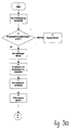
- FIGS. 3a, 3b and 3c show the simplified flow chart for the automatic control of the refilling process.
- buttons E1 and E2 Pressing the start button (button E1) establishes the power supply and first checks whether the input requirements have been met. If a system error is found, it will be reported.
- the protective flap 79 can be opened. Thereupon the print head 100 is to be inserted, possibly also the ink tank 20. After the protective flap 79 is closed, the filling process is started.
- the pump 40 When the pump 40 is started, two time intervals start, namely the time interval T6, which specifies the maximum duration of the filling process, and the further time interval T3, max, which monitors the pressure increase when the first cycle is completed. If the upper threshold value Po designated as “pressure level P2” is not reached within the predetermined time interval, there is a system error. In normal cases, however, the upper threshold value Po is reached in good time and the pump 40 is switched off. In the first cycle, a leak test is additionally carried out, which stops the refilling process in the event of a detected leak and, by reversing the feed pump 40, initiates the pressure reduction and the required negative pressure in the Ink supply room 105 produces.
- T6 which specifies the maximum duration of the filling process
- T3, max which monitors the pressure increase when the first cycle is completed.
- the time interval T3 is started immediately when the feed pump 40 is switched off, and it is monitored whether the lower threshold value Pu referred to as “pressure level P1” is reached within the maximum intended time interval T3, max. If this is the case, the feed pump 40 is started again and the cycle begins again.
- the cycle is now repeated until either the lower pressure level (threshold value Pu) is no longer reached during the maximum predetermined subinterval T3, max or the maximum predetermined filling time T6 has expired.
- ink is conveyed back into the ink tank 20 until the overpressure in the line 30 is completely reduced and then the intended underpressure in the ink supply space 105 is reached.
- the protective flap 79 can be opened and the print head 100 can be taken ready for operation.
Landscapes
- Ink Jet (AREA)
Applications Claiming Priority (2)
| Application Number | Priority Date | Filing Date | Title |
|---|---|---|---|
| DE19637235 | 1996-09-13 | ||
| DE1996137235 DE19637235C1 (de) | 1996-09-13 | 1996-09-13 | Verfahren zum Wiederbefüllen einer Tintenpatrone bzw. eines Druckkopfs eines Tintenstrahldruckers oder dergleichen |
Publications (2)
| Publication Number | Publication Date |
|---|---|
| EP0829362A2 true EP0829362A2 (fr) | 1998-03-18 |
| EP0829362A3 EP0829362A3 (fr) | 1999-03-24 |
Family
ID=7805468
Family Applications (1)
| Application Number | Title | Priority Date | Filing Date |
|---|---|---|---|
| EP97114276A Withdrawn EP0829362A3 (fr) | 1996-09-13 | 1997-08-19 | Méthode de remplissage de cartouches d'encre ou de tête d'impression pour imprimante par jet d'encre ou similaire |
Country Status (2)
| Country | Link |
|---|---|
| EP (1) | EP0829362A3 (fr) |
| DE (1) | DE19637235C1 (fr) |
Cited By (1)
| Publication number | Priority date | Publication date | Assignee | Title |
|---|---|---|---|---|
| EP0914955A3 (fr) * | 1997-10-07 | 1999-09-01 | PMS GmbH, Produktion + Recycling von Büromaschinenzubehör | Cartouche de recharge |
Families Citing this family (4)
| Publication number | Priority date | Publication date | Assignee | Title |
|---|---|---|---|---|
| WO2005016647A2 (fr) * | 2003-08-14 | 2005-02-24 | Nicodem Harry E | Appareil de remplissage de cartouches d'imprimante a jet d'encre et procedes associes |
| DE102004056013A1 (de) * | 2004-11-19 | 2006-05-24 | Christian Stern | Recycling- und Nachfüllvorrichtung für Druckerpatronen und Tonerkartuschen |
| US20080100678A1 (en) | 2006-10-30 | 2008-05-01 | Childers Winthrop D | Introducing ink into an ink cartridge |
| US7690741B2 (en) | 2006-10-30 | 2010-04-06 | Hewlett-Packard Development Company, L.P. | Introducing ink into an ink cartridge |
Family Cites Families (6)
| Publication number | Priority date | Publication date | Assignee | Title |
|---|---|---|---|---|
| US5199470B1 (en) * | 1991-05-17 | 1996-05-14 | Graphic Utilities Inc | Method and apparatus for refilling ink cartridges |
| US5396268A (en) * | 1992-03-27 | 1995-03-07 | Scitex Digital Printing, Inc. | Refill apparatus and method |
| JPH06191055A (ja) * | 1992-12-25 | 1994-07-12 | Canon Inc | インクジェット記録装置のインク再充填装置 |
| DE4327178C1 (de) * | 1993-08-13 | 1995-03-09 | Pms Gmbh Prod & Recycling | Vorrichtung zum Wiederbefüllen eines Druckkopfs eines Tintenstrahldruckers |
| US5369429A (en) * | 1993-10-20 | 1994-11-29 | Lasermaster Corporation | Continuous ink refill system for disposable ink jet cartridges having a predetermined ink capacity |
| DE4440561C2 (de) * | 1994-11-12 | 1996-10-24 | Pms Gmbh Prod & Recycling | Vorrichtung zum Wiederbefüllen eines Druckkopfs eines Tintenstrahldruckers |
-
1996
- 1996-09-13 DE DE1996137235 patent/DE19637235C1/de not_active Expired - Fee Related
-
1997
- 1997-08-19 EP EP97114276A patent/EP0829362A3/fr not_active Withdrawn
Cited By (1)
| Publication number | Priority date | Publication date | Assignee | Title |
|---|---|---|---|---|
| EP0914955A3 (fr) * | 1997-10-07 | 1999-09-01 | PMS GmbH, Produktion + Recycling von Büromaschinenzubehör | Cartouche de recharge |
Also Published As
| Publication number | Publication date |
|---|---|
| DE19637235C1 (de) | 1997-10-30 |
| EP0829362A3 (fr) | 1999-03-24 |
Similar Documents
| Publication | Publication Date | Title |
|---|---|---|
| DE3428434C2 (de) | Druckvorrichtung | |
| EP0711668A2 (fr) | Appareil de recharge pour cartouche d'impression par jet d'encre | |
| DE69231761T2 (de) | Tintenstrahldrucker | |
| DE602005000683T2 (de) | Flüssigkeitspatrone, Drucker, und Verfahren zum Steuern eines Druckers | |
| DE69309413T2 (de) | Tintennachfüllvorrichtung, Aufzeichnungsgerät mit dieser und Tintennachfüllverfahren | |
| DE3882662T2 (de) | Tintenstrahlaufzeichnungsvorrichtung. | |
| DE69635869T2 (de) | Tintenstrahlaufzeichnungsapparat für tintenpatrone | |
| DE69410127T2 (de) | Farbstrahlaufzeichnungsgerät | |
| DE69723497T2 (de) | Flüssigkeitnachfüllverfahren und -vorrichtung und Tintenstrahlaufzeichnungsgerät | |
| DE60118464T2 (de) | Tintenpatrone, tintenstrahlaufzeichnungsgerät mit einer solchen tintenpatrone und reinigungssteuerungsverfahren für aufzeichnungskopf des aufzeichnungsgerätes | |
| DE3316970C2 (fr) | ||
| DE69101979T2 (de) | Tintenstrahlgerät und seine Tintenkassette. | |
| DE69327916T2 (de) | Verfahren zum Prüfen des Entladungszustandes eines Tintenstrahlaufzeichnungskopfes und Tintenstrahlaufzeichnungsgerät, welches es verwendet | |
| DE602004005536T2 (de) | Getränkeausgabevorrichtung mit Kartuschenauswerfanordnung | |
| DE69034240T2 (de) | Tintenstrahlaufzeichnungsgerät und Tintenkassette dafür | |
| DE3417116C2 (fr) | ||
| DE69627906T2 (de) | Gerät und Verfahren für die Flüssigkeitsstrahlaufzeichnung | |
| DE69808772T2 (de) | Vorrichtung zur selbstinbetriebstellung eines tintenstrahldruckers | |
| DE69225052T2 (de) | Tintenstrahlaufzeichungsmittel und zugehörige Verpackung | |
| DE69220099T2 (de) | Tintenstrahlgerät | |
| DE69432725T2 (de) | Farbstrahlaufzeichnungsgerät mit Ablagenrückgewinnungsvorrichtung | |
| DE3203014A1 (de) | Tintenstrahldrucker und tintentropfenausstossvorrichtung sowie verfahren zur verhinderung ihres verstopfens durch tinte | |
| DE3244809A1 (de) | Tintenstrahlschreiber und tintenstrahl-schreibkopf hierfuer | |
| DE3128366A1 (de) | "tintenstrahldrucker" | |
| DE3608016C2 (fr) |
Legal Events
| Date | Code | Title | Description |
|---|---|---|---|
| PUAI | Public reference made under article 153(3) epc to a published international application that has entered the european phase |
Free format text: ORIGINAL CODE: 0009012 |
|
| AK | Designated contracting states |
Kind code of ref document: A2 Designated state(s): AT BE CH DE DK ES FI FR GB GR IE IT LI LU MC NL PT SE |
|
| PUAL | Search report despatched |
Free format text: ORIGINAL CODE: 0009013 |
|
| AK | Designated contracting states |
Kind code of ref document: A3 Designated state(s): AT BE CH DE DK ES FI FR GB GR IE IT LI LU MC NL PT SE |
|
| AKX | Designation fees paid | ||
| STAA | Information on the status of an ep patent application or granted ep patent |
Free format text: STATUS: THE APPLICATION IS DEEMED TO BE WITHDRAWN |
|
| 18D | Application deemed to be withdrawn |
Effective date: 19990925 |
|
| REG | Reference to a national code |
Ref country code: DE Ref legal event code: 8566 |