EP0829608A2 - Profil für Fenster oder Türen - Google Patents
Profil für Fenster oder Türen Download PDFInfo
- Publication number
- EP0829608A2 EP0829608A2 EP97111723A EP97111723A EP0829608A2 EP 0829608 A2 EP0829608 A2 EP 0829608A2 EP 97111723 A EP97111723 A EP 97111723A EP 97111723 A EP97111723 A EP 97111723A EP 0829608 A2 EP0829608 A2 EP 0829608A2
- Authority
- EP
- European Patent Office
- Prior art keywords
- profile
- locking
- groove
- bolt
- locking insert
- Prior art date
- Legal status (The legal status is an assumption and is not a legal conclusion. Google has not performed a legal analysis and makes no representation as to the accuracy of the status listed.)
- Withdrawn
Links
- XAGFODPZIPBFFR-UHFFFAOYSA-N aluminium Chemical compound [Al] XAGFODPZIPBFFR-UHFFFAOYSA-N 0.000 abstract description 3
- 229910052782 aluminium Inorganic materials 0.000 abstract description 3
- 239000000463 material Substances 0.000 description 3
- 238000003801 milling Methods 0.000 description 3
- 238000009434 installation Methods 0.000 description 2
- 238000005553 drilling Methods 0.000 description 1
- 238000003780 insertion Methods 0.000 description 1
- 230000037431 insertion Effects 0.000 description 1
- 238000004519 manufacturing process Methods 0.000 description 1
- 238000000034 method Methods 0.000 description 1
- 230000002787 reinforcement Effects 0.000 description 1
Images


Classifications
-
- E—FIXED CONSTRUCTIONS
- E05—LOCKS; KEYS; WINDOW OR DOOR FITTINGS; SAFES
- E05B—LOCKS; ACCESSORIES THEREFOR; HANDCUFFS
- E05B9/00—Lock casings or latch-mechanism casings ; Fastening locks or fasteners or parts thereof to the wing
- E05B9/002—Faceplates or front plates
-
- E—FIXED CONSTRUCTIONS
- E05—LOCKS; KEYS; WINDOW OR DOOR FITTINGS; SAFES
- E05C—BOLTS OR FASTENING DEVICES FOR WINGS, SPECIALLY FOR DOORS OR WINDOWS
- E05C9/00—Arrangements of simultaneously actuated bolts or other securing devices at well-separated positions on the same wing
- E05C9/22—Guides for sliding bars, rods or cables
-
- E—FIXED CONSTRUCTIONS
- E06—DOORS, WINDOWS, SHUTTERS, OR ROLLER BLINDS IN GENERAL; LADDERS
- E06B—FIXED OR MOVABLE CLOSURES FOR OPENINGS IN BUILDINGS, VEHICLES, FENCES OR LIKE ENCLOSURES IN GENERAL, e.g. DOORS, WINDOWS, BLINDS, GATES
- E06B3/00—Window sashes, door leaves, or like elements for closing wall or like openings; Layout of fixed or moving closures, e.g. windows in wall or like openings; Features of rigidly-mounted outer frames relating to the mounting of wing frames
- E06B3/04—Wing frames not characterised by the manner of movement
- E06B3/06—Single frames
- E06B3/08—Constructions depending on the use of specified materials
- E06B3/20—Constructions depending on the use of specified materials of plastics
- E06B3/22—Hollow frames
- E06B3/221—Hollow frames with the frame member having local reinforcements in some parts of its cross-section or with a filled cavity
- E06B3/222—Hollow frames with the frame member having local reinforcements in some parts of its cross-section or with a filled cavity with internal prefabricated reinforcing section members inserted after manufacturing of the hollow frame
-
- E—FIXED CONSTRUCTIONS
- E06—DOORS, WINDOWS, SHUTTERS, OR ROLLER BLINDS IN GENERAL; LADDERS
- E06B—FIXED OR MOVABLE CLOSURES FOR OPENINGS IN BUILDINGS, VEHICLES, FENCES OR LIKE ENCLOSURES IN GENERAL, e.g. DOORS, WINDOWS, BLINDS, GATES
- E06B3/00—Window sashes, door leaves, or like elements for closing wall or like openings; Layout of fixed or moving closures, e.g. windows in wall or like openings; Features of rigidly-mounted outer frames relating to the mounting of wing frames
- E06B3/32—Arrangements of wings characterised by the manner of movement; Arrangements of movable wings in openings; Features of wings or frames relating solely to the manner of movement of the wing
- E06B3/34—Arrangements of wings characterised by the manner of movement; Arrangements of movable wings in openings; Features of wings or frames relating solely to the manner of movement of the wing with only one kind of movement
- E06B3/36—Arrangements of wings characterised by the manner of movement; Arrangements of movable wings in openings; Features of wings or frames relating solely to the manner of movement of the wing with only one kind of movement with a single vertical axis of rotation at one side of the opening, or swinging through the opening
- E06B3/362—Double winged doors or windows
Definitions
- the invention relates to a profile for doors or windows.
- Profiles in particular plastic profiles with a space for a bar that can be moved in the longitudinal direction of the profile, are known. Profiles of this type are used above all with slip doors or slip windows in order to detachably fasten the door or window sash on the side opposite the hinge with the bolt on the frame or a baseboard.
- the bolt is guided in a hollow chamber of the profile.
- an opening is made in the hollow chamber, in which a mechanism for moving the bolt can be fastened.
- attaching the mechanics to the door or window leaf is time-consuming and labor-intensive.
- the same mechanism is used to move two latches that can be moved against each other and thus to connect the door or window on the top and bottom with the frame at the same time.
- long locking bars in the hollow chamber profile must be connected to the mechanics. This is also difficult and labor intensive.
- the invention is therefore based on the object of developing a generic profile so that simple installation of the bolt is possible.
- This object is achieved in the generic profile in that the space is designed as a groove extending in the longitudinal direction of the profile over the profile length.
- the design of the room as a groove has the great advantage that a mechanism for moving the bolt can be easily used at any point in the room.
- Both individual latches which can be fastened to the top and the underside of the door or window sash can be easily inserted into this groove-shaped space and can be fastened immediately.
- But above all bolts and their mechanics for simultaneous fastening of the upper and lower ends of the door or window sash to the frame are particularly easy to insert into the groove and to fasten there.
- An insertion of locking parts in hard-to-access hollow chamber profiles and complex milling work on the profile for fastening the mechanics are completely eliminated in the profile according to the invention.
- the bottom of the groove is concave. Since the bolt is usually designed as a round bar, the concave design of the groove base can serve as a guide for the bolt. Even if a separate locking guide is provided, the least amount of material is necessary if it is round and lies against the concave bottom of the groove.
- an advantageous embodiment of the groove provides undercuts in front, which allow the mechanics and / or guidance of the bolt to be pressed into the groove, thus creating a good connection between the space and the profile.
- the profile has a further groove for a locking bar which extends in the longitudinal direction of the profile over the length of the profile.
- a continuous groove for the locking bar provides space behind the locking bar, into which the bolt can be moved. Such a groove also reduces the milling work required on the profile when installing the locking bar.
- the profile is produced as an extruded profile or as an extruded profile.
- Extruded profiles can be produced quickly and inexpensively in large quantities and are therefore particularly suitable for the production of door and window profiles.
- Plastic is particularly suitable as the material for the profile according to the invention.
- An embodiment of the invention provides that the profile has a locking insert that extends over the entire length of the profile.
- a locking insert covers the groove over its entire length and includes all parts of the bolt which can be moved in the longitudinal direction of the profile.
- this locking insert has a locking guide extending over the length of the profile.
- This bolt guide allows the bolt to be easily installed and ensures straight locking of the bolt.
- the locking insert has a locking bar.
- the locking bar and locking insert can consist of two parts.
- a one-piece design is advantageous, which enables a continuous, preferably flat, covering of the groove provided in the profile.
- a particularly cost-effective solution provides that the locking insert is manufactured as an extruded profile.
- a preferred material for the locking insert and possibly the locking bar is aluminum.
- Aluminum is easy to process as an extruded profile and enables subsequent drilling or milling work to attach the locking insert to the rest of the profile or to insert the mechanics on the locking insert.
- FIG. 1 shows a section of a slip door 1 that has a door leaf 2 that can be pivoted over a floor profile 3.
- a profile 5 is attached in a vertical orientation.
- a bolt (not shown) is guided, which cooperates with a raised portion 6 arranged on the bottom bar 3 in order to lock the door leaf 2 on the bottom bar 3.
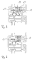
- the section shown in Figure 2 through the profile 5 shown in Figure 1 shows the inner structure of the faceplate profile 5.
- the profile 5 is an extruded profile part made of PVC, which has the same dimensions over its entire length.
- a first chamber 7 with a reinforcement 8 can be seen in cross section.
- Further chambers 9, 10, 11 are separated from one another by webs, some of which have circular cavities 12, 13 as screw channels.
- the profile 5 has a widened outside 14 with respect to the rest of the profile body and an inside 15 pointing to the other door leaf.
- This inside 15 has, after the outside 14, a space 16 for a bolt 17 which can be moved in the longitudinal direction of the profile 5.
- This space 16 is open to the inside 15 of the profile 5 and designed as a U-shaped groove 18.
- the profile 5 has a locking insert 19.
- This locking insert 19 covers the entire inside 15 of the rest of the profile with a flat side 20.
- the locking insert 19 has a locking guide 21, which is designed as a tube which rests on the concave bottom of the U-shaped groove 18.
- the locking insert 19 can easily be inserted into the rest of the profile 5. In the installed state, its side 20 covers both the uneven inside 15 of the rest of the profile and the bolt guide 21.
- FIGS. 3 and 4 show the use of the locking insert 19 as a locking bar.
- FIG. 3 shows a recess 22 in the side 20 of the locking insert 19, which is designed so that a bolt 23 can engage in the recess 22.
- FIG. 4 shows the redesign of the locking insert 19 in the area of the latch 24 of the door 1.
- Both in the area of the bolt 23 and in the area of the latch 24 are milled in areas in the locking insert 19 to enable the installation of conventional parts.
- the faceplate profile according to the invention thus enables the arrangement of the bolt guide 21 and the locking bar next to one another on the inside 15 of the profile.
Landscapes
- Engineering & Computer Science (AREA)
- Civil Engineering (AREA)
- Structural Engineering (AREA)
- Mechanical Engineering (AREA)
- Specific Sealing Or Ventilating Devices For Doors And Windows (AREA)
- Wing Frames And Configurations (AREA)
- Securing Of Glass Panes Or The Like (AREA)
- Joining Of Corner Units Of Frames Or Wings (AREA)
Abstract
Description
- Die Erfindung betrifft ein Profil für Türen oder Fenster.
- Profile, insbesondere Kunststoffprofile mit einem Raum für einen in Längsrichtung des Profils verschiebbaren Riegel sind bekannt. Derartige Profile werden vor allem bei Stülptüren oder Stülpfenstern eingesetzt, um den Tür- oder Fensterflügel auf der der Angel gegenüberliegenden Seite mit dem Riegel am Rahmen oder einer Bodenleiste lösbar zu befestigen.
- Bei diesen Profilen ist der Riegel in einer Hohlkammer des Profils geführt. Um den Riegel zu bewegen, ist in die Hohlkammer eine Öffnung eingearbeitet, in der eine Mechanik zur Bewegung des Riegels befestigbar ist. Das Anbringen der Mechanik am Tür- oder Fensterblatt ist jedoch zeit- und auch arbeitsaufwendig.
- Zum Teil wird auch die gleiche Mechanik verwendet, um zwei gegeneinander bewegbare Riegel zu bewegen und somit die Türe oder das Fenster an der Oberseite und der Unterseite gleichzeitig mit dem Rahmen zu verbinden. In diesem Fall müssen lange Riegelstangen im Hohlkammerprofil mit der Mechanik verbunden werden. Auch dies ist schwierig und arbeitsaufwendig.
- Der Erfindung liegt daher die Aufgabe zugrunde, ein gattungsgemäßes Profil so weiterzubilden, daß ein einfacher Einbau des Riegels möglich ist.
- Diese Aufgabe wird bei dem gattungsgemäßem Profil dadurch gelöst, daß der Raum als sich in Längsrichtung des Profils über die Profillänge erstreckende Nut ausgebildet ist.
- Die Ausbildung des Raums als Nut führt zu dem großen Vorteil, daß an jeder Stelle des Raums eine Mechanik zur Bewegung des Riegels leicht einsetzbar ist. Sowohl einzelne an der Oberseite und der Unterseite der Tür- oder Fensterflügel befestigbare Riegel sind leicht in diesen als Nut ausgebildeten Raum einsetzbar und sofort zu befestigen. Aber vor allem Riegel und deren Mechanik zur gleichzeitigen Befestigung des oberen und des unteren Endes des Tür- oder Fensterflügels am Rahmen sind besonders leicht in die Nut einsetzbar und dort zu befestigen. Ein Einführen von Riegelteilen in schwer zugängliche Hohlkammerprofile und aufwendige Fräsarbeiten am Profil zur Befestigung der Mechanik entfallen bei dem erfindungsgemäßen Profil vollständig.
- Vorteilhaft ist es, wenn der Boden der Nut konkav ausgebildet ist. Da der Riegel üblicherweise meist als Rundstab ausgebildet ist, kann die konkave Ausbildung des Nutbodens als Führung für den Riegel dienen. Auch wenn eine separate Riegelführung vorgesehen ist, ist der geringste Materialaufwand notwenig, wenn dieser rund ausgeführt ist und am konkaven Boden der Nut anliegt.
- Um die Riegelmechanik und/oder die Riegelführung fest im Profil zu halten, sieht eine vorteilhafte Ausgestaltung der Nut Hinterschneidungen vor, die es erlauben, die Mechanik und/oder Führung des Riegels in die Nut einzudrücken um somit eine gute Verbindung zwischen Raum und Profil zu bewirken.
- Vorteilhaft ist es darüberhinaus, wenn das Profil eine weitere, sich in Längsrichtung des Profils über die Profillänge erstreckende Nut für eine Schließleiste aufweist. Eine durchgehende Nut für die Schließleiste sorgt für Raum hinter der Schließleiste, in den der Riegel hineinbewegbar ist. Auch eine derartige Nut verringert die am Profil notwendigen Fräsarbeiten beim Einbau der Schließleiste.
- Besonders vorteilhaft ist es, wenn das Profil als Strangpreßprofil oder als extrudiertes Profil hergestellt ist. Strangpreßprofile sind schnell und kostengünstig in großen Mengen herstellbar und eignen sich daher besonders gut für die Herstellung von Tür- und Fensterprofilen.
- Als Werstoff ist für das erfindungsgemäße Profil vor allem Kunststoff geeignet.
- Eine Ausgestaltung der Erfindung sieht vor, daß das Profil einen Verriegelungseinsatz aufweist, der sich über die gesamte Länge des Profils erstreckt. Ein derartiger Verriegelungseinsatz deckt die Nut über ihre gesamte Länge ab und beinhaltet alle Teile des in Längsrichtung des Profils verschiebbaren Riegels.
- Vorteilhaft ist es, wenn dieser Verriegelungseinsatz eine sich über die Länge des Profils erstreckende Riegelführung aufweist. Diese Riegelführung erlaubt einen einfachen Einbau des Riegels und gewährleistet eine gerade Führung des Riegels.
- Vorteilhaft ist es darüberhinaus, wenn der Verriegelungseinsatz eine Schließleiste aufweist. Schließleiste und Verriegelungseinsatz können aus zwei Teilen bestehen. Vorteilhaft ist jedoch eine einteilige Ausführung, die eine durchgehende, vorzugsweise ebene Abdeckung der im Profil vorgesehenen Nut ermöglicht.
- Eine besonders kostengünstig herstellbare Lösung sieht vor, daß der Verriegelungseinsatz als Strangpreßprofil hergestellt ist.
- Ein bevorzugtes Material für den Verriegelungseinsatz und ggf. die Schließleiste ist Aluminium. Aluminium ist leicht als Strangpreßprofil zu verarbeiten und ermöglicht nachträgliche Bohr- oder Fräsarbeiten zur Befestigung des Verriegelungseinsatzes am Rest des Profiles oder zum Einführen der Mechanik am Verriegelungseinsatz.
- Ein Ausführungsbeispiel des erfindungsgemäßen Profils ist in der Zeichnung dargestellt und wird im folgenden näher beschrieben.
- Es zeigt,
- Figur 1
- eine perspektivische Darstellung eines in eine Türe eingebauten erfindungsgemäßen Profils,
- Figur 2
- einen Schnitt durch das erfindungsgemäße Profil längs der Linie II-II in Figur 1,
- Figur 3
- einen Schnitt durch das erfindungsgemäße Profil im Bereich eines Bolzen und
- Figur 4
- einen Schnitt durch das erfindungsgemäße Profil im Bereich der Falle des Türschlosses.
- In Figur 1 ist ein Ausschnitt einer Stülptüre 1 gezeigt, die ein Türblatt 2 aufweist, das über einem Bodenprofil 3 schwenkbar ist. An der den Angeln gegenüberliegenden Seite 4 des Türblattes 2 ist ein Profil 5 in senkrechter Ausrichtung angebracht. In diesem Profil ist ein Riegel (nicht gezeigt) geführt, der mit einer an der Bodenleiste 3 angeordneten Erhöhung 6 zusammenwirkt, um das Türblatt 2 an der Bodenleiste 3 zu verriegeln.
- Der in Figur 2 gezeigte Schnitt durch das in Figur 1 gezeigte Profil 5 zeigt den inneren Aufbau des Stulpprofils 5. Das Profil 5 ist ein Strangpreßprofilteil aus PVC, das über seine gesamte Länge die gleichen Abmessungen aufweist. Im Querschnitt ist eine erste Kammer 7 mit einer Verstärkung 8 erkennbar. Weitere Kammern 9, 10, 11 sind durch Stege voneinander getrennt, die zum Teil kreisförmige Hohlräume 12, 13 als Schraubkanäle aufweisen.
- Das Profil 5 hat eine gegenüber dem restlichen Profilkörper verbreiterte Außenseite 14 und eine zum anderen Türflügel weisende Innenseite 15. Diese Innenseite 15 weist im Anschluß an die Außenseite 14 einen Raum 16 für einen in Längsrichtung des Profils 5 verschiebbaren Riegel 17 auf. Dieser Raum 16 ist zur Innenseite 15 des Profils 5 offen und als U-förmige Nut 18 ausgebildet.
- Darüber hinaus weist das Profil 5 einen Verriegelungseinsatz 19 auf. Dieser Verriegelungseinsatz 19 deckt mit einer ebenen Seite 20 die gesamte Innenseite 15 des restlichen Profils ab. Außerdem hat der Verriegelungseinsatz 19 eine Riegelführung 21, die als Rohr ausgebildet, das am konkaven Boden der U-förmigen Nut 18 anliegt.
- Der Verriegelungseinsatz 19 ist einfach in das restliche Profil 5 einsetzbar. Seine Seite 20 verdeckt im eingebauten Zustand sowohl die unebene Innenseite 15 des restlichen Profils als auch die Riegelführung 21.
- Die Verwendung des Verriegelungseinsatzes 19 als Schließleiste zeigen die Figuren 3 und 4. Figur 3 zeigt eine Aussparung 22 in der Seite 20 des Verriegelungseinsatzes 19, die so ausgebildet ist, daß ein Bolzen 23 in die Ausnehmung 22 eingreifen kann.
- Figur 4 zeigt die Umgestalung des Verriegelungseinsatzes 19 im Bereich der Falle 24 der Türe 1.
- Sowohl im Bereich des Bolzens 23 als auch im Bereich der Falle 24 werden bereichsweise Einfräsungen in den Verriegelungseinsatz 19 vorgenommen, um den Einbau konventioneller Teile zu ermöglichen.
- Das erfindungsgemäße Stulpprofil ermöglicht somit die Anordnung von Riegelführung 21, und Schließleiste nebeneinander an der Innenseite 15 der Profils.
Claims (12)
- Profil für Türen (1) oder Fenster mit einem Raum (16) für einen in Längsrichtung des Profils verschiebbaren Riegel (17), dadurch gekennzeichnet, daß der Raum (16) als sich in Richtung des Profils (5) über die Profillänge erstreckende Nut (18) ausgebildet ist.
- Profil nach Anspruch 1, dadurch gekennzeichnet, daß das Profil ein Stulpprofil ist.
- Profil nach Anspruch 2, dadurch gekennzeichnet, daß es eine verbreiterte Außenseite (14) aufweist und die Nut (18) im Anschluß an die Außenseite (14) ausgebildet ist.
- Profil nach einem der vorhergehenden Ansprüche, dadurch gekennzeichnet, daß der Boden der Nut (18) konkav ausgebildet ist.
- Profil nach einem der vorhergehenden Ansprüche, dadurch gekennzeichnet, daß die Nut (18) eine Hinterschneidung aufweist.
- Profil nach einem der vorhergehenden Ansprüche, dadurch gekennzeichnet, daß das Profil (5) eine weitere sich in Längsrichtung des Profils über die Profillänge erstreckende Nut für eine Schließleiste aufweist.
- Profil nach einem der vorhergehenden Ansprüche, dadurch gekennzeichnet, daß das Profil (5) als Strangpreßprofil hergestellt ist.
- Profil nach einem der vorhergehenden Ansprüche, dadurch gekennzeichnet, daß das Profil (5) ein Kunststoffprofil ist.
- Profil nach einem der vorhergehenden Ansprüche, dadurch gekennzeichnet, daß das Profil (5) einen Verriegelungseinsatz (19) aufweist, der sich über die Länge des Profils (5) erstreckt.
- Profil nach Anspruch 9, dadurch gekennzeichnet, daß der Verriegelungseinsatz (19) eine sich über die Länge des Profils (5) erstreckende Riegelführung (21) aufweist.
- Profil nach Anspruch 9 oder 10, dadurch gekennzeichnet, daß der Verriegelungseinsatz (19) eine Schließleiste aufweist.
- Profil nach einem der Ansprüche 9 bis 11, dadurch gekennzeichnet, daß der Verriegelungseinsatz (19) als Strangpreßprofil hergestellt ist.
Applications Claiming Priority (2)
| Application Number | Priority Date | Filing Date | Title |
|---|---|---|---|
| DE19637111A DE19637111A1 (de) | 1996-09-12 | 1996-09-12 | Profil für Türen oder Fenster |
| DE19637111 | 1996-09-12 |
Publications (2)
| Publication Number | Publication Date |
|---|---|
| EP0829608A2 true EP0829608A2 (de) | 1998-03-18 |
| EP0829608A3 EP0829608A3 (de) | 1999-03-17 |
Family
ID=7805396
Family Applications (1)
| Application Number | Title | Priority Date | Filing Date |
|---|---|---|---|
| EP97111723A Withdrawn EP0829608A3 (de) | 1996-09-12 | 1997-07-10 | Profil für Fenster oder Türen |
Country Status (4)
| Country | Link |
|---|---|
| EP (1) | EP0829608A3 (de) |
| CZ (1) | CZ193497A3 (de) |
| DE (1) | DE19637111A1 (de) |
| PL (1) | PL184376B1 (de) |
Cited By (2)
| Publication number | Priority date | Publication date | Assignee | Title |
|---|---|---|---|---|
| RU2393314C2 (ru) * | 2006-02-09 | 2010-06-27 | Закрытое Акционерное Общество "Оконная Мануфактура" | Рамный профиль, система рамных профилей (варианты) и комплект поворотно-откидной фурнитуры для нее |
| EA020727B1 (ru) * | 2009-12-22 | 2015-01-30 | Рехау Аг + Ко | Дверь пластмассовая со стопорным устройством дверного замка, а также стопорное устройство дверного замка для нее |
Family Cites Families (9)
| Publication number | Priority date | Publication date | Assignee | Title |
|---|---|---|---|---|
| US3378290A (en) * | 1965-02-01 | 1968-04-16 | Mark M. Sekulich | Door locking and latching device |
| US3617080A (en) * | 1968-07-24 | 1971-11-02 | Wesley E Miller | Door latch |
| DE2401155B2 (de) * | 1974-01-10 | 1977-04-21 | VoIz, Georg, 6095 Ginsheim-Gustavsburg | Kunststoffprofilstab fuer fensterrahmen o.dgl. |
| DE3109124A1 (de) * | 1981-03-11 | 1982-09-23 | Wilh. Frank Gmbh, 7022 Leinfelden-Echterdingen | "treibstangenbeschlag zum einschieben in eine laengsnut eines rahmens eines fensters, einer tuer o.dgl." |
| DE3115573A1 (de) * | 1981-04-16 | 1982-12-02 | Hermann 7274 Haiterbach Hartl | Rahmenschenkel fuer fenster |
| NL8902841A (nl) * | 1989-11-16 | 1991-06-17 | Alprokon Promotie Ontwikk Bv | Deur-, raam- of paneelprofiel. |
| DE9217229U1 (de) * | 1992-12-17 | 1994-04-28 | Pax Schweikhard GmbH, 55218 Ingelheim | Schubstangenführung an Fenster- oder Türrahmen |
| DE9404559U1 (de) * | 1994-03-18 | 1994-05-19 | Willrich, Peter, 52388 Nörvenich | Durchgehende Schließleiste |
| DE4445793C1 (de) * | 1994-12-21 | 1995-12-21 | Siegenia Frank Kg | Fenster, Tür od. ähnlicher Öffnungsverschluß |
-
1996
- 1996-09-12 DE DE19637111A patent/DE19637111A1/de not_active Withdrawn
-
1997
- 1997-06-20 CZ CZ971934A patent/CZ193497A3/cs unknown
- 1997-07-10 EP EP97111723A patent/EP0829608A3/de not_active Withdrawn
- 1997-09-01 PL PL97321883A patent/PL184376B1/pl not_active IP Right Cessation
Cited By (2)
| Publication number | Priority date | Publication date | Assignee | Title |
|---|---|---|---|---|
| RU2393314C2 (ru) * | 2006-02-09 | 2010-06-27 | Закрытое Акционерное Общество "Оконная Мануфактура" | Рамный профиль, система рамных профилей (варианты) и комплект поворотно-откидной фурнитуры для нее |
| EA020727B1 (ru) * | 2009-12-22 | 2015-01-30 | Рехау Аг + Ко | Дверь пластмассовая со стопорным устройством дверного замка, а также стопорное устройство дверного замка для нее |
Also Published As
| Publication number | Publication date |
|---|---|
| PL321883A1 (en) | 1998-03-16 |
| EP0829608A3 (de) | 1999-03-17 |
| DE19637111A1 (de) | 1998-03-19 |
| CZ193497A3 (cs) | 1998-03-18 |
| PL184376B1 (pl) | 2002-10-31 |
Similar Documents
| Publication | Publication Date | Title |
|---|---|---|
| EP0009652B1 (de) | Bausatz für vertikale oder horizontale Schiebefenster | |
| EP0056484B1 (de) | Mit einem Stulpschienenbeschlag ausgerüsteter Tür- oder Fensterflügel | |
| EP0666396B1 (de) | Sicherheitstür und Sicherheitsvorrichtung zum Einbau in eine Tür | |
| DE102016125602A1 (de) | Isolierkörper für mehrschalige Bauelemente | |
| DE29612478U1 (de) | Türschwellenprofil | |
| DE2810058A1 (de) | Riegelschloss | |
| DE9313426U1 (de) | Lüftungsvorrichtung für Räume | |
| EP0114218A2 (de) | Fenster oder Tür mit Beplankungsleisten aus Holz oder Kunststoff | |
| DE602004004982T2 (de) | Eckumlenkung für Türen und Fenster | |
| DE29704349U1 (de) | Hohlprofil, insbesondere aus Kunststoff, zur Bildung eines Abdeckrahmens zur Verkleidung von Holzrahmen | |
| DE10208975A1 (de) | Kunststofffenster oder -tür | |
| DE19637111A1 (de) | Profil für Türen oder Fenster | |
| EP0829603B1 (de) | Verriegelungseinsatz für Türen- oder Fensterprofile | |
| EP2072744B1 (de) | Zargenprofil für eine Hebe-Schiebetür | |
| CH624449A5 (en) | Device for connecting a covering frame to a base frame for windows, facades or room partitions | |
| DE4325698A1 (de) | Nebentür | |
| DE4403870A1 (de) | Sicherheitstür | |
| EP1559856B1 (de) | Fenster, Tür oder dergleichen mit einem Stulpschienenbeschlag | |
| EP4102021B1 (de) | Fenster- oder tür-hohlkammerprofil, system mit einem solchen hohlkammerprofil und daraus hergestellter rahmen | |
| DE29724136U1 (de) | Verriegelungseinsatz für Türen- oder Fensterprofile | |
| DE10048954C2 (de) | Rahmensystem mit T-Stossverbindung | |
| DE19944172B4 (de) | Rechteckfeld einer Rahmenfüllung | |
| AT392817B (de) | Riegelschloss | |
| DE2401155B2 (de) | Kunststoffprofilstab fuer fensterrahmen o.dgl. | |
| DE29800306U1 (de) | Beschlag für einen Flügelrahmen von Fenstern oder Türen |
Legal Events
| Date | Code | Title | Description |
|---|---|---|---|
| PUAI | Public reference made under article 153(3) epc to a published international application that has entered the european phase |
Free format text: ORIGINAL CODE: 0009012 |
|
| AK | Designated contracting states |
Kind code of ref document: A2 Designated state(s): AT BE CH DE DK ES FI FR GB GR IE IT LI LU MC NL PT SE |
|
| AX | Request for extension of the european patent |
Free format text: AL;LT;LV;RO;SI |
|
| PUAL | Search report despatched |
Free format text: ORIGINAL CODE: 0009013 |
|
| AK | Designated contracting states |
Kind code of ref document: A3 Designated state(s): AT BE CH DE DK ES FI FR GB GR IE IT LI LU MC NL PT SE |
|
| AX | Request for extension of the european patent |
Free format text: AL;LT;LV;RO;SI |
|
| RAP1 | Party data changed (applicant data changed or rights of an application transferred) |
Owner name: WILLRICH, PETER |
|
| RIN1 | Information on inventor provided before grant (corrected) |
Inventor name: WILLRICH, PETER |
|
| AKX | Designation fees paid | ||
| STAA | Information on the status of an ep patent application or granted ep patent |
Free format text: STATUS: THE APPLICATION IS DEEMED TO BE WITHDRAWN |
|
| 18D | Application deemed to be withdrawn |
Effective date: 19990918 |
|
| REG | Reference to a national code |
Ref country code: DE Ref legal event code: 8566 |