EP0829652A2 - Raccord - Google Patents
Raccord Download PDFInfo
- Publication number
- EP0829652A2 EP0829652A2 EP97114540A EP97114540A EP0829652A2 EP 0829652 A2 EP0829652 A2 EP 0829652A2 EP 97114540 A EP97114540 A EP 97114540A EP 97114540 A EP97114540 A EP 97114540A EP 0829652 A2 EP0829652 A2 EP 0829652A2
- Authority
- EP
- European Patent Office
- Prior art keywords
- connection
- joining
- screw
- joint
- partner
- Prior art date
- Legal status (The legal status is an assumption and is not a legal conclusion. Google has not performed a legal analysis and makes no representation as to the accuracy of the status listed.)
- Withdrawn
Links
- 230000007704 transition Effects 0.000 claims abstract description 18
- 230000015572 biosynthetic process Effects 0.000 claims abstract description 7
- 239000000853 adhesive Substances 0.000 claims description 12
- 230000001070 adhesive effect Effects 0.000 claims description 12
- 239000002775 capsule Substances 0.000 claims description 2
- 238000010079 rubber tapping Methods 0.000 claims description 2
- 230000003993 interaction Effects 0.000 claims 2
- 238000004026 adhesive bonding Methods 0.000 claims 1
- 230000009172 bursting Effects 0.000 claims 1
- 229910052751 metal Inorganic materials 0.000 description 4
- 239000002184 metal Substances 0.000 description 4
- 238000005336 cracking Methods 0.000 description 2
- 238000006073 displacement reaction Methods 0.000 description 2
- 230000000694 effects Effects 0.000 description 2
- 238000007689 inspection Methods 0.000 description 2
- 230000008719 thickening Effects 0.000 description 2
- 244000025254 Cannabis sativa Species 0.000 description 1
- 235000012766 Cannabis sativa ssp. sativa var. sativa Nutrition 0.000 description 1
- 235000012765 Cannabis sativa ssp. sativa var. spontanea Nutrition 0.000 description 1
- 229910000831 Steel Inorganic materials 0.000 description 1
- 239000000956 alloy Substances 0.000 description 1
- 229910045601 alloy Inorganic materials 0.000 description 1
- 229910052782 aluminium Inorganic materials 0.000 description 1
- XAGFODPZIPBFFR-UHFFFAOYSA-N aluminium Chemical compound [Al] XAGFODPZIPBFFR-UHFFFAOYSA-N 0.000 description 1
- 235000009120 camo Nutrition 0.000 description 1
- 235000005607 chanvre indien Nutrition 0.000 description 1
- 230000003111 delayed effect Effects 0.000 description 1
- 238000001514 detection method Methods 0.000 description 1
- 230000002349 favourable effect Effects 0.000 description 1
- 239000011888 foil Substances 0.000 description 1
- 239000011487 hemp Substances 0.000 description 1
- 238000003780 insertion Methods 0.000 description 1
- 230000037431 insertion Effects 0.000 description 1
- 230000007257 malfunction Effects 0.000 description 1
- 238000005058 metal casting Methods 0.000 description 1
- 238000012544 monitoring process Methods 0.000 description 1
- 239000002985 plastic film Substances 0.000 description 1
- 229920006255 plastic film Polymers 0.000 description 1
- 239000010959 steel Substances 0.000 description 1
- 238000002604 ultrasonography Methods 0.000 description 1
- 230000003313 weakening effect Effects 0.000 description 1
Images
Classifications
-
- F—MECHANICAL ENGINEERING; LIGHTING; HEATING; WEAPONS; BLASTING
- F16—ENGINEERING ELEMENTS AND UNITS; GENERAL MEASURES FOR PRODUCING AND MAINTAINING EFFECTIVE FUNCTIONING OF MACHINES OR INSTALLATIONS; THERMAL INSULATION IN GENERAL
- F16B—DEVICES FOR FASTENING OR SECURING CONSTRUCTIONAL ELEMENTS OR MACHINE PARTS TOGETHER, e.g. NAILS, BOLTS, CIRCLIPS, CLAMPS, CLIPS OR WEDGES; JOINTS OR JOINTING
- F16B31/00—Screwed connections specially modified in view of tensile load; Break-bolts
- F16B31/02—Screwed connections specially modified in view of tensile load; Break-bolts for indicating the attainment of a particular tensile load or limiting tensile load
- F16B31/021—Screwed connections specially modified in view of tensile load; Break-bolts for indicating the attainment of a particular tensile load or limiting tensile load by means of a frangible part
Definitions
- the invention relates to a joint connection which is alternately loaded by an axial force flow between zero and different maximum values.
- DE 43 22 717 A1 discloses a joint connection by means of which, in the case of a three-part commercial vehicle frame consisting of front axle and rear axle supports made of light metal casting, and of a longitudinal support center piece connecting the front axle supports to the rear axle supports, a firm connection of the axle longitudinal supports to the longitudinal support center piece formed by light metal extruded profiles is achieved becomes.
- the joining connection is formed by a sleeve-shaped connecting element which forms a joining partner and is introduced into the inner contour of a hollow profile of the longitudinal member center piece which represents the other joining partner, with a positive and non-positive connection.
- the connecting element provided there with an internal thread is fastened, for example by screwing, to the respective axle support.
- the joint connection is subjected to extremely high loads due to alternating loads in the axial direction, ie tension and pressure, as well as transverse loads during the driving operation of the commercial vehicle, the connection being overloaded during the operating period, preferably in the region of the end of the connecting element located in the profile, due to the lack of elasticity or can occur excessive voltage that lead to a tearing of the profile due to a sudden fatigue fracture. This break in the profile cannot be seen beforehand. By tearing the profile, the joint connection is destroyed and the connecting element loses its load-bearing capacity, whereupon the respective axle carrier detaches from the center piece. Depending on the type of cargo being loaded, unpredictable consequences of an accident can occur during operation.
- the invention is based on the object of specifying a joint connection in which the failure of an overload-related fatigue fracture at the end pointing in the joining direction can be recognized in a simple manner by the functional joint connection before it occurs.
- a joint connection is presented with a pressure relief bolt, which has an outer joining partner formed as a hollow profile with a ring and an inner joining partner which is inserted in the outer form-fitting manner with a shaft section.
- said shaft section is provided with a screw head, which does not come into contact in the normal operating state and is therefore subject to play and can only transmit forces in the event of a malfunction, while the forces in the operating state in another area are positively and free of play through a shear bolt on the ring be transmitted.
- the shear pin is designed as a predetermined breaking point, which shears when an admissible load is exceeded and breaks at this point.
- the play-free area of said shaft section is located in the ring. Not least due to the position of the predetermined breaking point and that of the two joining partners to one another, the entire joining connection is dimensioned such that a residual joining connection which can be subjected to alternating stress remains after the shear bolt breaks.
- a screw connection can be removed, which consists of a cap screw which penetrates the parts to be connected to one another and a screw nut which can be screwed onto it and which has an out-of-round circumference at one of its two ends for attaching a wrench.
- the nut has a ring-shaped wall weakening on part of the height of its thread, which when tightening the nut with a wrench, while one end is supported against the one of the parts to be connected, breaks when a certain torque is exceeded, so that when the wrench is turned further, one of the two parts of the nut that become independent tightened against the other and thereby one Thread lock is formed in the manner of lock nuts.
- the fatigue fracture of the joint connection is shifted from the connection end pointing in the joining direction to the other connection end, the breakage of one of the joining partners not immediately destroying the entire connection. Rather, a residual connection remains in that the joining partners overlap in a connection-effective manner on a reduced connection length.
- the required strength for the connection against further axial alternating loads - also against overloads - and thus an adequate load-bearing capacity of the connection is given. This has a prolonging effect on the service life of the joint, since after the first break it only fails completely if a fatigue crack occurs at the end of the joint pointing in the joining direction.
- the joining direction is the direction of the translatory insertion movement of the inner joining partner into the outer joining partner when joining the two joining partners.
- the first crack can be seen as a harbinger of the later breaking of the joint.
- the crack runs through the location of the predetermined breaking point between the connection ends due to the sudden increase in the axial extensibility of the joint connection, i.e. as a result of a stiffness jump, immediately behind the point on the side of the joint connection end, locally defined in the transverse direction of the joint connection, so that, for example, in the inspection to assess the Resilience condition in a simple manner and at low cost, the said location can be examined to determine whether a crack has occurred or not. If the easily recognizable, locally brought forward first crack can then be intervened accordingly by renewing the joint connection partner, so that the joint connection is again fully functional with regard to its resilience. Serious consequential damage, in particular when using the joint connection on frame parts of commercial vehicles, is avoided in this way and the safety of the vehicle during driving is thus increased.
- the invention causes the joint connection to fail in two steps, which follow one another clearly in terms of time and location, and when the first crack occurs, but the connection still remains stable, i.e. resilient, regular monitoring of the site can already take place when the connection finally fails.
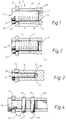
- FIG. 1 shows a joint connection designed as a screw connection 1, which can preferably be used in vehicles, in particular commercial vehicles, tractor units.
- the front and rear axle supports which are designed as light metal cast alloy parts 2, must be attached to a side member intermediate module, which is formed by a plurality of light metal extruded hollow profiles 3, for the assembly of a lightweight module frame.
- the hollow profile 3 has an internal thread 4, into which the screw 5 is screwed with the external thread 6 of its shaft 7.
- the screw 5 is additionally glued to the hollow profile 3 over a partial length of its shaft 7 from the beginning of the engagement of the thread 6.4 in the vicinity of the screw head 8, that is to say from the front connection end 16, the adhesive hardening and thereby the screw connection 1 into one front play-free 9 and a directly adjoining rear play area 10.
- the overlap length of the hollow profile 3 and screw 5 is at least 2.5 times the screw diameter, so that the permissible surface pressure or the yield point of the screw 5 is not exceeded.
- the minimum overlap length is in the range of 1.1 times the screw diameter.
- the screw connection 1 is very stiff and of very low elasticity, in particular in the axial direction of the screw connection 1, in such a way that it exceeds the low elasticity of the screw connection 1 at the connection end 11 pointing in the joining direction.
- this connection end 11 due to the low axial extensibility of the connection, there is normally an excessive voltage when overloaded, which leads to fatigue after some time and thus to a tear of the joint connection.
- the screw connection 1 does not come off completely because it has a play area 10 which, after the cracking at the transition 12, can take over the supporting function of the screw connection 1 alone. This is illustrated by the dotted lines of force flow 13 and 14 of FIGS. 1 and 2.
- the force flow of the screw connection 1 occurs under normal, damage-free stress play-free area 9 from the screw 5 to the hollow profile 3 and continues in this. After the crack-forming overload, the force flow according to FIG. 2 extends into the original play area 10, only to then transfer to the hollow profile 3.
- transition 12 forming the predetermined breaking point
- the hollow profile 3 at the connection end 11 has a circumferential wall thickening 15, which is intended to increase the stability of the connection at this point, so that the displacement of a crack 17 to the predetermined breaking point is promoted . Furthermore, by locating a circumferential notch on the circumference of the hollow profile 3 at the location of the transition 12, the location of the crack 17 can be further strengthened.
- the crack 17 takes place along the transition 12 in the circumferential direction of the screw connection 1.
- the predetermined location of the crack 17 makes it easy to recognize during the inspection whether the entire joint connection is in danger of being destroyed or not. If, for example, the screw connection 1 is designed so that the wall thickness of the hollow profile 3 is relatively small to the screw thickness, the hollow profile 3 breaks at the transition 12, which is visually visible since the hollow profile 3 is the outer one of the joining partners. However, if the wall thickness of the hollow profile 3 is large compared to the screw thickness, the screw 5 breaks, the front area 9 of the screw connection 1 with play having the further supporting function of the connection. The resulting crack 17 is not optically visible and must be detected by relevant detection devices, for example based on ultrasound or for measuring the electrical conductivity.
- the screw connection 1 has no wall thickening 15 at the connection end 11 pointing in the joining direction.
- the thread-bearing bore of the hollow profile 3 at the connection end 11 is provided with a smooth cylindrical axial extension 18, a so-called "undercut", rounded with a barrel radius with a large radius of curvature is.
- a play-free area 9 is possible in a variety of ways.
- the screw 5 can be glued to the hollow profile 3.
- a microencapsulated two-component adhesive, which is distributed in the threads of the screw 5, is favorable for this purpose.
- the capsules each containing an adhesive component burst due to the shear forces that occur, the adhesive components mixing and forming a particularly strong and stiff adhesive connection of the two joining partners after curing.
- a screw with a self-tapping thread on a section is also conceivable, the inside diameter of the bore of the hollow profile 3 on this section having to be smaller than the outside diameter of the outside thread 6.
- a metallic intermediate layer such as a metal foil strip or a stranded tape, with which the screw 5 is screwed into the hollow profile 3, the play-free area 9 being formed with this subsection.
- Non-metallic intermediate layers such as hemp or a plastic film strip can also be used as an alternative.
- FIG. 4 Another type of joint connection is shown in FIG. 4.
- the inner joining partner is formed by a plug pin 19, while the outer tubular joining partner 20 in contrast to the hollow profile 3 of the screw connection 1 is threadless.
- the plug pin 19 is inserted into the joining partner 20 and is held by two transverse pins 21 and 22 which are pressed into mutually aligned transverse bores 23 and 24 and 25 and 26 of the joining partner 19, 20.
- the cross pin 21 is inserted into the front cross bores 23 and 24 to form a play-free press fit both in the socket pin 19 and in the joining partner 20.
- the cross pin 22, however, is press-fitted in the rear transverse bore 26 of the joining partner 20, but within the rear transverse bore 25 of the plug pin 19 with a lot of play.
- the transverse bore 25 is widened in the manner of an elongated hole in the axial direction of the joint connection.
- a further possibility of fastening the plug pin 19 in the joining partner 20 consists in an adhesive bond, a front area of the plug pin 19 covered with a curing adhesive forming a very rigid, axially only slightly elastic connection with the joining partner 20, and the rear connecting to this area Area of the plug pin 19 is glued to the joining partner 20 by means of a permanently elastic adhesive, which permits deflections of the plug pin 19 in the axial direction within the scope of play.
- a joint connection is proposed that separates the connection in regions of different axial extensibility of the inner joint partner 5, 19 introduced into the outer joint partner designed as a hollow profile 3, 20, the change in the extensibility at the point of transition 12 of the regions into one another erratic.
- this transition 12 instead of the end 11 of the connection pointing in the joining direction in the event of overloads, excessive stresses occur, due to which, due to fatigue, after a certain number of load cycles there is a crack 17 on one of the two joining partners depending on the design of the ratio of the wall thickness of the profile 3.20 to the thickness of the inner joining partner 5.19.
- a fatigue fracture at the end of the connection pointing in the joining direction is thereby delayed.
- the transition 12 between the areas 9, 10 represents a locally predetermined breaking point, at which the occurrence of a first crack 17 preceding the crack that dissolves the joint, axially displaced at a distance from it, as an indicator of the load-bearing condition of the joint and thus as an indication acts on a later complete failure of the joint connection.
Landscapes
- Engineering & Computer Science (AREA)
- General Engineering & Computer Science (AREA)
- Mechanical Engineering (AREA)
- Mutual Connection Of Rods And Tubes (AREA)
- Quick-Acting Or Multi-Walled Pipe Joints (AREA)
Applications Claiming Priority (2)
| Application Number | Priority Date | Filing Date | Title |
|---|---|---|---|
| DE19637592A DE19637592C1 (de) | 1996-09-14 | 1996-09-14 | Fügeverbindung |
| DE19637592 | 1996-09-14 |
Publications (2)
| Publication Number | Publication Date |
|---|---|
| EP0829652A2 true EP0829652A2 (fr) | 1998-03-18 |
| EP0829652A3 EP0829652A3 (fr) | 1999-03-31 |
Family
ID=7805706
Family Applications (1)
| Application Number | Title | Priority Date | Filing Date |
|---|---|---|---|
| EP97114540A Withdrawn EP0829652A3 (fr) | 1996-09-14 | 1997-08-22 | Raccord |
Country Status (3)
| Country | Link |
|---|---|
| US (1) | US5938383A (fr) |
| EP (1) | EP0829652A3 (fr) |
| DE (1) | DE19637592C1 (fr) |
Cited By (1)
| Publication number | Priority date | Publication date | Assignee | Title |
|---|---|---|---|---|
| WO2022258646A1 (fr) * | 2021-06-08 | 2022-12-15 | B. Braun Melsungen Ag | Système de connexion pour applications médicales |
Families Citing this family (7)
| Publication number | Priority date | Publication date | Assignee | Title |
|---|---|---|---|---|
| DE19804458C2 (de) * | 1998-02-05 | 2002-11-07 | Daimler Chrysler Ag | Einrichtung zur Erkennung eines überbelastungsbedingten Ermüdungsbruches einer Schraubverbindung |
| CA2425091C (fr) * | 2003-04-11 | 2009-01-20 | Karel Bostik | Raccord a joints de cisaillement |
| DE202006004794U1 (de) * | 2006-03-23 | 2007-07-26 | Weidmüller Interface GmbH & Co. KG | Gehäuse |
| CA2688801C (fr) * | 2009-12-17 | 2013-04-23 | Weatherford/Lamb, Inc. | Assemblage a raccord de cisaillement destine a servir avec des pompes rotatives et des pompes a piston |
| EP3474303B1 (fr) * | 2017-10-18 | 2023-05-17 | EUCHNER GmbH + Co. KG | Actionneur |
| CN107882438A (zh) * | 2018-01-03 | 2018-04-06 | 北京首航科学技术开发有限公司 | 可调式快卸锁及其锁座 |
| US11988237B2 (en) * | 2020-07-31 | 2024-05-21 | Spirit Aerosystems, Inc. | System including breakaway fasteners for fabrication of composite parts |
Citations (3)
| Publication number | Priority date | Publication date | Assignee | Title |
|---|---|---|---|---|
| DE1944805A1 (de) | 1968-09-09 | 1970-11-05 | Vaughn Rudolf M | Verschraubung |
| US3599528A (en) | 1969-08-21 | 1971-08-17 | Allied Chem | Pressure relief bolt |
| DE4322717A1 (de) | 1993-07-08 | 1995-01-12 | Daimler Benz Ag | Rahmen für Nutzfahrzeuge |
Family Cites Families (8)
| Publication number | Priority date | Publication date | Assignee | Title |
|---|---|---|---|---|
| US1957784A (en) * | 1932-08-30 | 1934-05-08 | Charles E Johnson | Self-locking valve tappet |
| US3405751A (en) * | 1966-07-15 | 1968-10-15 | Thompson Wendell L | Element having continuous thread, portion of thread being longitudinally variable inlength |
| US3602976A (en) * | 1969-09-15 | 1971-09-07 | Mac Lean Fogg Lock Nut Co | Method for controlling clamping load of a threaded fastener |
| US4097108A (en) * | 1975-02-03 | 1978-06-27 | Sicame | Hot line clamps |
| US4244661A (en) * | 1979-07-23 | 1981-01-13 | Mcdonnell Douglas Corporation | Fastener means and joint for laminates |
| US4661031A (en) * | 1982-06-04 | 1987-04-28 | R&H Technology, Inc. | Fatigue resistant fastener assembly |
| DE3725792A1 (de) * | 1987-08-04 | 1989-02-16 | Schwan Stabilo Schwanhaeusser | Einrichtung mit einem schraubelement und einem mutterelement, und verwendung der einrichtung |
| US5018920A (en) * | 1989-01-23 | 1991-05-28 | Mcdonnell Douglas Corporation | Interference fit bolt and sleeve |
-
1996
- 1996-09-14 DE DE19637592A patent/DE19637592C1/de not_active Expired - Fee Related
-
1997
- 1997-08-22 EP EP97114540A patent/EP0829652A3/fr not_active Withdrawn
- 1997-09-15 US US08/929,259 patent/US5938383A/en not_active Expired - Fee Related
Patent Citations (3)
| Publication number | Priority date | Publication date | Assignee | Title |
|---|---|---|---|---|
| DE1944805A1 (de) | 1968-09-09 | 1970-11-05 | Vaughn Rudolf M | Verschraubung |
| US3599528A (en) | 1969-08-21 | 1971-08-17 | Allied Chem | Pressure relief bolt |
| DE4322717A1 (de) | 1993-07-08 | 1995-01-12 | Daimler Benz Ag | Rahmen für Nutzfahrzeuge |
Cited By (1)
| Publication number | Priority date | Publication date | Assignee | Title |
|---|---|---|---|---|
| WO2022258646A1 (fr) * | 2021-06-08 | 2022-12-15 | B. Braun Melsungen Ag | Système de connexion pour applications médicales |
Also Published As
| Publication number | Publication date |
|---|---|
| EP0829652A3 (fr) | 1999-03-31 |
| US5938383A (en) | 1999-08-17 |
| DE19637592C1 (de) | 1997-11-13 |
Similar Documents
| Publication | Publication Date | Title |
|---|---|---|
| EP0487890B1 (fr) | Jonction d'élément, en particulier d'un joint à brides | |
| DE4310002C1 (de) | Schallentkoppelndes Verbindungselement | |
| EP2232089B1 (fr) | Insert fileté et pièce de véhicule | |
| DE60221488T2 (de) | Lagervorrichtung für eine Ritzelachswelle und ein Endreduktionsgetriebe für Fahrzeuge | |
| DE202007010709U1 (de) | Spannanordnung sowie Abdrück- und Konusring dafür | |
| DE69919484T2 (de) | Aufgeweitetes Rohr und Verbindungsanordnung hierfür | |
| DE10031427A1 (de) | Käfig für ein Wälzlager | |
| DE19804458C2 (de) | Einrichtung zur Erkennung eines überbelastungsbedingten Ermüdungsbruches einer Schraubverbindung | |
| EP0534001B1 (fr) | Assemblage à vis pour assembler deux pièces de construction, qui ont vue distance, notamment des plaques de métal | |
| DE19637592C1 (de) | Fügeverbindung | |
| DE102005033810A1 (de) | Lenker für eine Fahrzeugradaufhängung mit einer Sollbruchstelle | |
| DE102013213514A1 (de) | Sicherungsvorrichtung zum Sichern einer Mutter gegen ungewolltes Losdrehen, sowie Lageranordnung einer Welle | |
| DE102009025151A1 (de) | Befestigungsanordnung und Verfahren zur Befestigung eines Schwungrads oder Schwungradteils an einer Kurbelwelle einer Brennkraftmaschine | |
| EP1298333B1 (fr) | Ecrou auto-blocage accouplant rigidement pour un assemblage vissé | |
| DE1816880A1 (de) | Befestigungsvorrichtung mit automatischer Begrenzung des aufgebrachten Drehmoments | |
| EP0457249B1 (fr) | Attelage de remorque mot clef: dispositif antiperte avec distance de sécurité | |
| DE3726179C2 (de) | Kupplung fuer eine fahrzeug-lenksaeule | |
| WO1990008272A1 (fr) | Raccord a bride resistant a la torsion | |
| EP1277892B1 (fr) | Manchon pour lier des ronds à béton | |
| DE19735753A1 (de) | Drehstabanordnung | |
| DE102017004778A1 (de) | Toleranzausgleichende Verbindungsanordnung und Bauteilanordnung, insbesondere eines motornahen Funktionsbauteils und eines Motorblocks | |
| DE102007017700A1 (de) | Verliersicherung für eine Nutmutter bei einer Welle-Nabe-Verbindung | |
| DE202005003708U1 (de) | Bauteil mit Aussengewinde zum Einsetzen in ein Innengewinde | |
| DE10339431B4 (de) | Radbolzen für die Befestigung eines Fahrzeugrades | |
| DE102005055822B4 (de) | Hülsenanordnung |
Legal Events
| Date | Code | Title | Description |
|---|---|---|---|
| PUAI | Public reference made under article 153(3) epc to a published international application that has entered the european phase |
Free format text: ORIGINAL CODE: 0009012 |
|
| AK | Designated contracting states |
Kind code of ref document: A2 Designated state(s): ES FR GB IT SE |
|
| AX | Request for extension of the european patent |
Free format text: AL;LT;LV;RO;SI |
|
| PUAL | Search report despatched |
Free format text: ORIGINAL CODE: 0009013 |
|
| AK | Designated contracting states |
Kind code of ref document: A3 Designated state(s): AT BE CH DE DK ES FI FR GB GR IE IT LI LU MC NL PT SE |
|
| AX | Request for extension of the european patent |
Free format text: AL;LT;LV;RO;SI |
|
| RAP1 | Party data changed (applicant data changed or rights of an application transferred) |
Owner name: DAIMLERCHRYSLER AG |
|
| 17P | Request for examination filed |
Effective date: 19990306 |
|
| AKX | Designation fees paid |
Free format text: ES FR GB IT SE |
|
| REG | Reference to a national code |
Ref country code: DE Ref legal event code: 8566 |
|
| STAA | Information on the status of an ep patent application or granted ep patent |
Free format text: STATUS: THE APPLICATION HAS BEEN WITHDRAWN |
|
| 18W | Application withdrawn |
Withdrawal date: 20001021 |