EP0829669A1 - Soupape à pointeau - Google Patents
Soupape à pointeau Download PDFInfo
- Publication number
- EP0829669A1 EP0829669A1 EP97306553A EP97306553A EP0829669A1 EP 0829669 A1 EP0829669 A1 EP 0829669A1 EP 97306553 A EP97306553 A EP 97306553A EP 97306553 A EP97306553 A EP 97306553A EP 0829669 A1 EP0829669 A1 EP 0829669A1
- Authority
- EP
- European Patent Office
- Prior art keywords
- needle
- valve according
- actuator
- housing
- valve
- Prior art date
- Legal status (The legal status is an assumption and is not a legal conclusion. Google has not performed a legal analysis and makes no representation as to the accuracy of the status listed.)
- Withdrawn
Links
Images
Classifications
-
- F—MECHANICAL ENGINEERING; LIGHTING; HEATING; WEAPONS; BLASTING
- F16—ENGINEERING ELEMENTS AND UNITS; GENERAL MEASURES FOR PRODUCING AND MAINTAINING EFFECTIVE FUNCTIONING OF MACHINES OR INSTALLATIONS; THERMAL INSULATION IN GENERAL
- F16K—VALVES; TAPS; COCKS; ACTUATING-FLOATS; DEVICES FOR VENTING OR AERATING
- F16K47/00—Means in valves for absorbing fluid energy
- F16K47/08—Means in valves for absorbing fluid energy for decreasing pressure or noise level and having a throttling member separate from the closure member, e.g. screens, slots, labyrinths
- F16K47/16—Means in valves for absorbing fluid energy for decreasing pressure or noise level and having a throttling member separate from the closure member, e.g. screens, slots, labyrinths the throttling member being a cone
-
- F—MECHANICAL ENGINEERING; LIGHTING; HEATING; WEAPONS; BLASTING
- F16—ENGINEERING ELEMENTS AND UNITS; GENERAL MEASURES FOR PRODUCING AND MAINTAINING EFFECTIVE FUNCTIONING OF MACHINES OR INSTALLATIONS; THERMAL INSULATION IN GENERAL
- F16K—VALVES; TAPS; COCKS; ACTUATING-FLOATS; DEVICES FOR VENTING OR AERATING
- F16K1/00—Lift valves or globe valves, i.e. cut-off apparatus with closure members having at least a component of their opening and closing motion perpendicular to the closing faces
- F16K1/32—Details
- F16K1/52—Means for additional adjustment of the rate of flow
Definitions
- This invention relates to needle valves for controlling fluid flow.
- needle valve is used for sub-sea situations especially in the oil industry, where the valve is to be operated by a possibly remote controlled unmanned submersible vehicle.
- the valve is opened or closed by a movement of less than 360° of an external knob which is usually a tee-shaped handle.
- the problem is to ensure that the valve is fully opened or closed by the movement, and to avoid damage through excess movement.
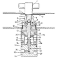
- the needle per se is indicated by the reference 15 and seats at 25 so as to prevent flow through the passage system 26,27.
- the needle has a flange 28 at its opposite end and this is engaged in a shoe at the foot of stem 11.
- the stem extends through a pair of spring carriers 13,17 which between them locate a helical compression spring 19.
- a lower ( in the drawing) spring carrier 17 is generally inverted cup shaped and its base 29 is, in the illustration showing a valve in the closed position and in this particular instance, spaced from the upper spring carrier 13 by clearance 30.
- the upper spring carrier has a male screw threaded spigot 31 engaged in a female screw threaded bore in neck 32 of housing 14, which is secured to the valve body 24, in which the mentioned passage 26,27 is formed.
- the upper end of the spigot 31 has a pair of diametrically related dogs which are located in the space 33, although not seen in the drawing.
- Knob 1 is integral with stem adaptor 5 which has an internal chamber to accommodate the upper end of the stem 11, and the stem end is maintained captive therein by a collar 9 and cotter pin 7.
- the lower end of adaptor 5 is adapted to engage the dogs for example by a pair of diametrically located cut-away portions also not seen in the drawing.
- top cover 6 which surrounds the stem adaptor and is engaged with the exterior of the part 32 and this creates a further chamber 35 which locates stop part 10.
- This comprises a ring with a radially projecting portion which co-operates with an abutment (not seen in this view) formed on the upper end surface of the neck 32.
- the ring is angularly fast, but adjustable in position, on the stem adaptor 5 for example by co-operating splines or hexagonal formations on the exterior of the stem adaptor and the bore of the ring at the point where they interfit.
- the needle in assembly, it is possible to have the needle seated under a desired spring pressure as represented by appropriate clearances, and then locate the ring in an appropriate angular position relative to the stem adaptor so that the stop and abutment faces are engaged. It will be appreciated that the needle can be in the seated position with the knob and cover removed so as to facilitate this setting up stage in assembly because the spring compression is held by the inter-engaged screw threads on the parts 31 and 32.
- the radial stop could be adjusted in only 60° increments. It is preferred to use a larger number as might be possible for example by using the hexagonal external shape but providing the ring with a twelve sided bore so that it could be adjusted in 30° increments.
Landscapes
- Engineering & Computer Science (AREA)
- General Engineering & Computer Science (AREA)
- Mechanical Engineering (AREA)
- Lift Valve (AREA)
Applications Claiming Priority (2)
| Application Number | Priority Date | Filing Date | Title |
|---|---|---|---|
| GB9618122 | 1996-08-30 | ||
| GBGB9618122.7A GB9618122D0 (en) | 1996-08-30 | 1996-08-30 | Needle valve |
Publications (1)
| Publication Number | Publication Date |
|---|---|
| EP0829669A1 true EP0829669A1 (fr) | 1998-03-18 |
Family
ID=10799173
Family Applications (1)
| Application Number | Title | Priority Date | Filing Date |
|---|---|---|---|
| EP97306553A Withdrawn EP0829669A1 (fr) | 1996-08-30 | 1997-08-27 | Soupape à pointeau |
Country Status (2)
| Country | Link |
|---|---|
| EP (1) | EP0829669A1 (fr) |
| GB (2) | GB9618122D0 (fr) |
Citations (7)
| Publication number | Priority date | Publication date | Assignee | Title |
|---|---|---|---|---|
| AT1922B (fr) * | 1899-05-15 | 1900-08-10 | Johann Bruendl | |
| US1991052A (en) * | 1931-06-13 | 1935-02-12 | John H Derby | Combined hose and reducing valve |
| US2605077A (en) * | 1947-12-05 | 1952-07-29 | Air Reduction | Combined needle and flush valve assembly |
| DE1960566U (de) * | 1966-11-18 | 1967-05-18 | Siemens Ag | Ventil zum steuern und/oder absperren von stroemenden medien. |
| US3347271A (en) * | 1964-07-03 | 1967-10-17 | Max F Ellerbusch | By-pass valve |
| US5299776A (en) * | 1993-03-26 | 1994-04-05 | Siemens Automotive L.P. | Impact dampened armature and needle valve assembly |
| GB2294528A (en) * | 1994-09-06 | 1996-05-01 | Pacson Ltd | Needle valve |
Family Cites Families (4)
| Publication number | Priority date | Publication date | Assignee | Title |
|---|---|---|---|---|
| GB923116A (en) * | 1960-05-23 | 1963-04-10 | Zeiss Jena Veb Carl | Improvements in or relating to needle valves, particularly for high-vacuum apparatus |
| GB1445588A (en) * | 1973-10-23 | 1976-08-11 | English Electric Co Ltd | Fluid-flow control valve |
| ZA774494B (en) * | 1976-08-06 | 1978-06-28 | Flow Ind Inc | Ultra-high pressure valving device for water jet cutting |
| DE3247490A1 (de) * | 1982-12-22 | 1984-06-28 | Deutsche Babcock Werke AG, 4200 Oberhausen | Armatur |
-
1996
- 1996-08-30 GB GBGB9618122.7A patent/GB9618122D0/en active Pending
-
1997
- 1997-08-26 GB GB9717863A patent/GB2317438A/en not_active Withdrawn
- 1997-08-27 EP EP97306553A patent/EP0829669A1/fr not_active Withdrawn
Patent Citations (7)
| Publication number | Priority date | Publication date | Assignee | Title |
|---|---|---|---|---|
| AT1922B (fr) * | 1899-05-15 | 1900-08-10 | Johann Bruendl | |
| US1991052A (en) * | 1931-06-13 | 1935-02-12 | John H Derby | Combined hose and reducing valve |
| US2605077A (en) * | 1947-12-05 | 1952-07-29 | Air Reduction | Combined needle and flush valve assembly |
| US3347271A (en) * | 1964-07-03 | 1967-10-17 | Max F Ellerbusch | By-pass valve |
| DE1960566U (de) * | 1966-11-18 | 1967-05-18 | Siemens Ag | Ventil zum steuern und/oder absperren von stroemenden medien. |
| US5299776A (en) * | 1993-03-26 | 1994-04-05 | Siemens Automotive L.P. | Impact dampened armature and needle valve assembly |
| GB2294528A (en) * | 1994-09-06 | 1996-05-01 | Pacson Ltd | Needle valve |
Also Published As
| Publication number | Publication date |
|---|---|
| GB9717863D0 (en) | 1997-10-29 |
| GB9618122D0 (en) | 1996-10-09 |
| GB2317438A (en) | 1998-03-25 |
Similar Documents
| Publication | Publication Date | Title |
|---|---|---|
| US5074519A (en) | Fail-close hydraulically actuated control choke | |
| US5392805A (en) | Frost-resistant hydrant | |
| US4309022A (en) | Poppet valve actuator apparatus | |
| US7225830B1 (en) | Fluid control valve | |
| CA1294599C (fr) | Dispositif modulaire de commande hydraulique | |
| US6588724B2 (en) | On-off valves for high pressure fluids | |
| US20200096114A1 (en) | Pilot-actuated spool valve having rod retainer | |
| US20130320252A1 (en) | Control valve assembly | |
| US11092248B2 (en) | Serviceable and adjustable full bore ball valve trim arrangement | |
| EP0962622B1 (fr) | Unité de commande électrohydraulique | |
| US6352239B1 (en) | Gate valve actuator override mechanism | |
| US11703893B2 (en) | Gas pressure reducer with cam commanded shut-off valve | |
| GB1562840A (en) | Selective back seat valve | |
| US11009138B2 (en) | Flow maximizer | |
| EP0305177B1 (fr) | Soupape de décharge | |
| GB2131069A (en) | Safety valves for wells | |
| US6953182B2 (en) | Retainer lock nut for fluid pressure control device | |
| GB2317438A (en) | Needle valve | |
| CN101451447B (zh) | 用于可变排量内燃发动机的气门操作系统 | |
| US4616805A (en) | Fuel shut-off valve | |
| US3727630A (en) | Non-leak valve of plastic construction | |
| US9353883B2 (en) | Excess pressure safety relief valve | |
| US5829734A (en) | Shut-off valve | |
| US20050023497A1 (en) | Valve packing removal device | |
| EP0426915B1 (fr) | Vanne comportant une pièce d'insertion amovible |
Legal Events
| Date | Code | Title | Description |
|---|---|---|---|
| PUAI | Public reference made under article 153(3) epc to a published international application that has entered the european phase |
Free format text: ORIGINAL CODE: 0009012 |
|
| AK | Designated contracting states |
Kind code of ref document: A1 Designated state(s): AT BE CH DE DK ES FR GB IE IT LI NL PT SE |
|
| AX | Request for extension of the european patent |
Free format text: AL;LT;LV;RO;SI |
|
| 17P | Request for examination filed |
Effective date: 19980403 |
|
| AKX | Designation fees paid |
Free format text: AT BE CH DE DK ES FR GB IE IT LI NL PT SE |
|
| RBV | Designated contracting states (corrected) |
Designated state(s): AT BE CH DE DK ES FR GB IE IT LI NL PT SE |
|
| 17Q | First examination report despatched |
Effective date: 19991115 |
|
| STAA | Information on the status of an ep patent application or granted ep patent |
Free format text: STATUS: THE APPLICATION IS DEEMED TO BE WITHDRAWN |
|
| 18D | Application deemed to be withdrawn |
Effective date: 20000328 |