EP0829734A2 - Méthode et dispositf de mesure de la différence du temps de parcours d'un signal électrique, électromagnétique ou acoustique - Google Patents
Méthode et dispositf de mesure de la différence du temps de parcours d'un signal électrique, électromagnétique ou acoustique Download PDFInfo
- Publication number
- EP0829734A2 EP0829734A2 EP97114393A EP97114393A EP0829734A2 EP 0829734 A2 EP0829734 A2 EP 0829734A2 EP 97114393 A EP97114393 A EP 97114393A EP 97114393 A EP97114393 A EP 97114393A EP 0829734 A2 EP0829734 A2 EP 0829734A2
- Authority
- EP
- European Patent Office
- Prior art keywords
- preferred value
- value
- threshold voltage
- transit time
- test
- Prior art date
- Legal status (The legal status is an assumption and is not a legal conclusion. Google has not performed a legal analysis and makes no representation as to the accuracy of the status listed.)
- Granted
Links
Images

Classifications
-
- G—PHYSICS
- G01—MEASURING; TESTING
- G01F—MEASURING VOLUME, VOLUME FLOW, MASS FLOW OR LIQUID LEVEL; METERING BY VOLUME
- G01F1/00—Measuring the volume flow or mass flow of fluid or fluent solid material wherein the fluid passes through a meter in a continuous flow
- G01F1/66—Measuring the volume flow or mass flow of fluid or fluent solid material wherein the fluid passes through a meter in a continuous flow by measuring frequency, phase shift or propagation time of electromagnetic or other waves, e.g. using ultrasonic flowmeters
- G01F1/667—Arrangements of transducers for ultrasonic flowmeters; Circuits for operating ultrasonic flowmeters
-
- G—PHYSICS
- G01—MEASURING; TESTING
- G01F—MEASURING VOLUME, VOLUME FLOW, MASS FLOW OR LIQUID LEVEL; METERING BY VOLUME
- G01F23/00—Indicating or measuring liquid level or level of fluent solid material, e.g. indicating in terms of volume or indicating by means of an alarm
- G01F23/22—Indicating or measuring liquid level or level of fluent solid material, e.g. indicating in terms of volume or indicating by means of an alarm by measuring physical variables, other than linear dimensions, pressure or weight, dependent on the level to be measured, e.g. by difference of heat transfer of steam or water
- G01F23/28—Indicating or measuring liquid level or level of fluent solid material, e.g. indicating in terms of volume or indicating by means of an alarm by measuring physical variables, other than linear dimensions, pressure or weight, dependent on the level to be measured, e.g. by difference of heat transfer of steam or water by measuring the variations of parameters of electromagnetic or acoustic waves applied directly to the liquid or fluent solid material
- G01F23/296—Acoustic waves
- G01F23/2962—Measuring transit time of reflected waves
-
- G—PHYSICS
- G04—HOROLOGY
- G04F—TIME-INTERVAL MEASURING
- G04F10/00—Apparatus for measuring unknown time intervals by electric means
Definitions
- the invention relates to a method and a device for measuring the transit time difference of an electrical, electromagnetic or acoustic signal according to the preamble of claim 1 and according to the preamble of claim 11.
- the transit time measurement for example of an ultrasound signal, is based on the fact that a pulse-shaped sound signal is coupled into the measuring medium by a transmitter transducer and is detected by a receiver transducer after passing through the measuring section.
- the sound propagation time is the time difference between the transmission process and the arrival of the ultrasound signal at the receiving location.
- the transmitted sound signal is reflected at a boundary layer between the measuring medium and an adjacent medium before it reaches the receiving transducer.
- a single sound transducer can also be operated alternately as a transmit and receive transducer.
- the pulse-front method is described in the above-mentioned document, which is based on the fact that the pulse front of the analog received signal is detected by means of a comparator and a signal zero crossing is detected with the aid of a second comparator.
- One with the The transmission process started runtime counter is stopped when this zero crossing comparator responds. A runtime measurement that is almost independent of the received signal amplitude is thus possible.
- the evaluation of the pulse front is made more difficult if the shape of the received signal, in particular the transient response, changes compared to a reference state.
- Cause can e.g. B. an increased sound propagation loss of the current measuring medium or a deviating from the reference medium speed of sound. Such influences can greatly deform the pulse front. Since the pulse front is represented by a group of rising vibrations, it is not always guaranteed that the half-wave desired for the measurement can be reliably detected.
- the runtime difference t1 - t2 is usually very small compared to the absolute runtime values t1 and t2. If the signal shape changes as a result of changed sound propagation conditions, it can occur with a fixed level of the received signal comparator that in the Different vibrations of the received signal are detected in both signal directions.
- the signals received in the two signal directions have comparatively small settling behavior differences that are significant for the detection of a half-wave and are dependent on the flow velocity. If different vibrations are detected, the transit time difference is incorrectly measured by at least one period T of the vibrations. This causes a very large measurement error since the maximum transit time difference in ultrasonic flow meters is usually only one to two periods of the ultrasonic oscillation.
- the invention has for its object to provide a method and a device for measuring the transit time difference of an electrical, electromagnetic or acoustic signal, which significantly improve the security of detection of the same, but at least a known half-wave of the received signal in transit time measurements with opposite signal directions.
- the new method of the type mentioned has the features mentioned in the characterizing part of claim 1 and the new device in the characterizing part of claim 11.
- Advantageous developments of the invention are specified in the dependent claims.
- the invention has the advantage that automatic adjustment of the threshold voltage of the received signal comparator is made possible. This leads to a significantly increased measuring certainty in the case of changing measuring conditions, such as occur in ultrasonic flow measurement according to the time-of-flight difference principle with changing measuring media or changing flow rates.
- the threshold voltage is tracked as a function of the result of a simple plausibility check and can therefore be carried out during normal measurement operation. The improved measuring accuracy therefore does not have to be bought with a reduction in the measuring rate.
- the invention can be implemented practically without additional circuitry if a measuring device is provided with a microprocessor for sequence control. A check and possible adjustment of the preferred value can then be implemented on the existing hardware by loading a suitable operating program. A corresponding sequence control can also be implemented by implementing a hardware control unit.
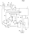
- a microcontroller 1 which takes over all control and evaluation functions, outputs a binary control signal 2 to a commutator 3 for setting the operating mode of the measuring device.
- the commutator 3 allows two ultrasonic transducers 4 and 5 to be operated alternately as transmitters and receivers.
- the converter 4 works as a transmitter
- the converter 5 as a receiver.
- the microcontroller 1 generates a pulse-shaped signal on a line 6 via a transmission amplifier 7 and the commutator 3 to excite the transmission converter 4.
- a runtime counter 9 for measuring the runtime of an ultrasound signal 10 is started.
- the ultrasound signal 10 emitted into a measuring medium reaches the receiving transducer 5 after passing through a measuring section and is converted there into an electrical signal on a line 11.
- This electrical signal is amplified with a reception amplifier 12 and simultaneously fed as a reception signal on a line 13 to a first comparator 14 and a second comparator 15.
- the received signal is compared with a first threshold voltage on a line 16, which is generated in the microcontroller 1 by a digital-to-analog converter DAC.
- the first comparator 14 delivers a positive output signal on a line 17 when the received signal is greater than the threshold voltage.
- the first threshold voltage is set to is outside of the noise on line 13 and that the arrival of a wave group at the receive converter 5 is indicated in the desired manner by the first comparator 14. This will be discussed in more detail later. If the received signal on line 13 exceeds the first threshold voltage, this leads to a positive edge on line 17, which causes a first D flip-flop 18 to switch if the event occurs within a measurement window that microcontroller 1 receives through a High level on a line 19 specifies.
- the Q output of the first D flip-flop 18 is connected via a line 20 to the data input of a second D flip-flop 21. A high level on line 20 enables second D flip-flop 21 to generate a stop signal on line 22.
- the second comparator 15 is supplied on a line 23 with a second threshold voltage which corresponds approximately to the reference potential of the received signal.
- the second comparator 15 thus always switches in the vicinity of the zero crossings of the received signal.
- Controllable inverters connected downstream of the two comparators 14 and 15, which are used for specifying the polarity in the detection of half-waves and signal zero crossings, are not shown for the sake of clarity and can be disregarded in clarifying the principle.
- the output of the second comparator 15 is connected to a clock input of the second D flip-flop 21.
- the Q output of the second D flip-flop 21 thus changes its state with the first rising edge at its clock input after the arrival of a group of waves has been detected by the first comparator 14.
- a previously open gate 24 of the runtime counter 9 locked so that further pulses of a quartz oscillator 25 are no longer counted.
- the frequency of the quartz oscillator 25 is in the range of a few megahertz.
- the start time of a runtime measurement is indicated to the runtime counter 9 by the microcontroller 1 through a line 26 also routed to the gate 24.
- the content of the runtime counter is taken over by microcontroller 1 and processed further.
- the first D flip-flop 18 and the second D flip-flop 21 are reset by a reset pulse on a line 27.
- the microcontroller 1 switches the commutator 3, and a transit time measurement is carried out in a similar manner in the opposite direction of the signal.
- the runtime difference is obtained by simple calculation.
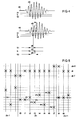
- FIG. 2 shows, by way of example, a time diagram to illustrate the mode of operation of the circuit according to FIG. 1.
- a transit time measurement is initiated by a pulse 28, which is fed to converter 4, for example, via line 6 (FIG. 1).
- the first threshold voltage the magnitude of which is indicated by a broken line 29 in FIG. 2, is set such that the second negative half-wave of a group of oscillations of a received signal 30 is detected.
- the running time counter 9 (FIG. 1) is stopped with the zero crossing following the detected half-wave, marked by a circle 31 in FIG. 2. For this purpose, with a rising edge 32 of an output signal 33 of the first comparator 14 on the line 17 (FIG.
- a value of the first threshold voltage is determined, with which a vibration of the received signal is always selected, which clearly differs in amplitude from the previous vibration and which at the same time "far ahead" in the group of rising and falling vibrations.
- a suitable method for this purpose will be explained with reference to FIG. 3.
- the microcontroller 1 Controlled by the microcontroller 1 (FIG. 1), the first threshold voltage is varied over the entire or a partial range of the value range covered by the received signal, and the transit time is measured in each case.
- the value range of a received signal 36 is indicated in FIG. 3 by a dimension arrow 37, the selected zero crossings being indicated by circles 38.
- the frequencies for positive first threshold voltages and negative signal zero crossings are in the middle diagram in FIG. 3 with thicker bars, those with negative first threshold voltages and positive signal zero crossings frequencies obtained are shown qualitatively with thinner bars.
- the frequency distribution H is plotted on the ordinate and the transit time t1 on the abscissa.
- the frequencies determined are weighted with an evaluation function g (tl). The weighted frequencies obtained in this way are shown in the lower diagram in FIG.
- the signal half-wave is finally selected with a frequency bar 39 and the first threshold voltage is preferably placed in the middle of the voltage range, which is limited by the amplitude peak values of the detected half-wave of the received signal and the previous half-wave of the same polarity.
- the half-wave is selected, which results in optimum measurement reliability with a very good signal / noise ratio.
- the time intervals for a periodic selection of a half-wave during the measuring operation can be selected to be considerably larger than the intervals between the individual measurements.
- the ratio can e.g. B. 10,000 or more.
- the new preferred value cannot be set to one of the two test values S1 or S2, but can only be shifted in the direction of one of the two test values S1 or S2.
- the shift is advantageously carried out in a step which is significantly smaller than the amount by which the two test values S1 and S2 deviate from the preferred value S. This ensures that individual incorrect measurements do not immediately lead to significant shifts in the preferred value due to noise in the received signal.
- the cycle Zn begins with a transit time measurement at time t0, at which the first threshold voltage is set to the current preferred value Vn. Since an invalid transit time measurement value was obtained in the previous transit time measurement, the calculated transit time difference, which has the value dt-T, is also invalid at time t0.
- the time of flight measurement at time t0 is followed by another time of flight measurement with the preferred value Vn at time t1.
- the valid value of the time of flight difference dt is now calculated from these two time of flight measurements.
- the first threshold voltage is set to test values P1 ... P6 above and below the preferred value Vn.
- the distance between the test values and the preferred value Vn is gradually increased until a runtime is measured for the test value P6 at time t7 which leads to a transit time difference dt + T which deviates by the duration T of an oscillation.
- This measured value is again rejected as invalid and the preferred value Vn + 1 of the next cycle Zn + 1 is shifted up one step, since the test value P6 with the incorrect measurement lies below the previous preferred value Vn.
- the new cycle Zn + 1 again begins with two transit time measurements with the new preferred value Vn + 1 at times t8 and t9, the calculation of the transit time difference at time t8 being rejected as invalid due to the incorrect transit time measurement at time t7.
- This cyclical checking and tracking of the preferred values advantageously ensures that the preferred value is always in the middle of the range between the amplitude peak of the detected half-wave and that of the previous half-wave.
- Such a setting of the first threshold voltage is characterized by an optimal signal-to-noise ratio.
- the measured transit time does not change due to a shift in the first threshold voltage.
- the checking of the preferred values can thus take place during the measuring operation and does not require any additional time which could have a negative effect on the measuring rate.
- An implementation with a device according to FIG. 1 is associated with little effort since, controlled by the microcontroller 1, only the digital values output to the digital-to-analog converter DAC need to be incremented or decremented in order to change the first threshold voltage step by step to set To produce test values.
- the transit time differences measured in the test values P2 ... P6 are each compared with the last measured and therefore only indirectly with the transit time difference measured with the preferred value Vn, since no measurement with the preferred value Vn takes place between the individual test values .
- a short cycle time and rapid adjustment of the preferred value are achieved even with a small increment of increasing the distance between successive test values.
- the transit time differences can be shifted over a cycle in smaller steps by a total of more than one oscillation period T, without this already causing a change in the current preferred value.
- a direct comparison of the transit time differences measured in the test values with those measured in the preferred value can be carried out by inserting one or more measurements with the preferred value between the measurements in the test values.
- a shorter cycle time can also be achieved by ignoring uncritical test values that are close to the preferred value.
Landscapes
- Physics & Mathematics (AREA)
- General Physics & Mathematics (AREA)
- Electromagnetism (AREA)
- Fluid Mechanics (AREA)
- Acoustics & Sound (AREA)
- Thermal Sciences (AREA)
- Measuring Volume Flow (AREA)
- Measurement Of Unknown Time Intervals (AREA)
- Measurement Of Mechanical Vibrations Or Ultrasonic Waves (AREA)
Applications Claiming Priority (2)
| Application Number | Priority Date | Filing Date | Title |
|---|---|---|---|
| DE19636945A DE19636945A1 (de) | 1996-09-11 | 1996-09-11 | Verfahren und Einrichtung zur Messung der Laufzeitdifferenz eines elektrischen, elektromagnetischen oder akustischen Signals |
| DE19636945 | 1996-09-11 |
Publications (3)
| Publication Number | Publication Date |
|---|---|
| EP0829734A2 true EP0829734A2 (fr) | 1998-03-18 |
| EP0829734A3 EP0829734A3 (fr) | 1998-09-23 |
| EP0829734B1 EP0829734B1 (fr) | 2004-10-27 |
Family
ID=7805284
Family Applications (1)
| Application Number | Title | Priority Date | Filing Date |
|---|---|---|---|
| EP97114393A Expired - Lifetime EP0829734B1 (fr) | 1996-09-11 | 1997-08-20 | Méthode et dispositf de mesure de la différence du temps de parcours d'un signal électrique, électromagnétique ou acoustique |
Country Status (4)
| Country | Link |
|---|---|
| EP (1) | EP0829734B1 (fr) |
| AT (1) | ATE280956T1 (fr) |
| DE (2) | DE19636945A1 (fr) |
| DK (1) | DK0829734T3 (fr) |
Cited By (4)
| Publication number | Priority date | Publication date | Assignee | Title |
|---|---|---|---|---|
| FR2803383A1 (fr) * | 1999-12-29 | 2001-07-06 | Schlumberger Ind Sa | Procede et dispositif de detection d'un dysfonctionnement pour un debitmetre a ultrasons |
| WO2005114112A2 (fr) | 2004-05-22 | 2005-12-01 | Robert Bosch Gmbh | Determination de l'instant de reception d'un signal ultrasonore par detection de forme d'impulsion |
| DE102005035584A1 (de) * | 2005-07-29 | 2007-02-01 | Hydrometer Gmbh | Verfahren zur Durchführung von Durchflussmessungen in einem strömenden Fluid |
| CN118443105A (zh) * | 2024-05-08 | 2024-08-06 | 中国计量大学 | 一种环鸣法超声流量计的飞行时间测量方法及系统 |
Families Citing this family (10)
| Publication number | Priority date | Publication date | Assignee | Title |
|---|---|---|---|---|
| AUPQ061399A0 (en) * | 1999-05-27 | 1999-06-17 | University Of Sydney, The | Acoustic flow meters |
| DE10118934C2 (de) * | 2001-04-18 | 2003-09-18 | Hydrometer Gmbh | Verfahren zur Justierung und zur Alterungskontrolle von Messgeräten mit Ultraschallwandlern |
| DE10318779B4 (de) * | 2003-04-25 | 2005-09-15 | Hydrometer Gmbh | Verfahren zur Justierung und zur Alterskontrolle von Messgeräten mit Ultraschallwandlern |
| AT6511U3 (de) | 2003-07-16 | 2004-09-27 | Avl List Gmbh | Ultraschall-gasdurchflusssensor sowie vorrichtung zur messung von abgas-strömungen von verbrennungskraftmaschinen sowie ein verfahren zur ermittlung des durchflusses von gasen |
| DE102004027958B4 (de) * | 2004-06-08 | 2007-07-12 | M & Fc Holding Llc | Verfahren und Vorrichtung zum Messen der Strömungsgeschwindigkeit von Fluiden |
| DE102011089152A1 (de) * | 2011-12-20 | 2013-06-20 | Endress + Hauser Gmbh + Co. Kg | Verfahren und Messgerät zur Abstandsmessung |
| CN105698886B (zh) * | 2016-05-04 | 2019-05-24 | 湖北锐意自控系统有限公司 | 一种基于超声波检测技术的气体流量检测方法 |
| JP7219582B2 (ja) * | 2018-10-17 | 2023-02-08 | アズビル株式会社 | 超音波流量計、流量計測方法、および流量演算装置 |
| JP7248407B2 (ja) * | 2018-10-17 | 2023-03-29 | アズビル株式会社 | 超音波流量計、流量計測方法、および流量演算装置 |
| DE102023127522B3 (de) | 2023-10-09 | 2024-12-12 | Sonovum Gmbh | Bestimmung einer absoluten Laufzeit von Signalen |
Family Cites Families (12)
| Publication number | Priority date | Publication date | Assignee | Title |
|---|---|---|---|---|
| US4028938A (en) * | 1976-01-26 | 1977-06-14 | Ocean Research Equipment, Inc. | Acoustical flow meter |
| NL7801401A (nl) * | 1978-02-07 | 1979-08-09 | Tno | Stelsel voor het meten van de snelheid en/of het debiet van een fluidum. |
| JPS5827449B2 (ja) * | 1978-08-09 | 1983-06-09 | 富士電機株式会社 | 超音波伝搬時間検出回路装置 |
| DE2950902A1 (de) * | 1979-12-18 | 1981-07-23 | Me Meerestechnik Elektronik Gmbh, 2351 Trappenkamp | Empfangsschaltung fuer die laufzeitmessung von schallsignalen |
| CH670896A5 (fr) * | 1986-08-13 | 1989-07-14 | Zellweger Uster Ag | |
| US5012449A (en) * | 1989-06-30 | 1991-04-30 | Ferranti O.R.E. Inc. | Sonic flow meter |
| DE3923349A1 (de) * | 1989-07-14 | 1991-01-24 | Haiges Elektronik Gmbh | Verfahren und anordnung zur bestimmung des empfangszeitpunktes eines ultraschallsignales |
| EP0452531B1 (fr) * | 1990-04-20 | 1995-01-04 | Siemens Aktiengesellschaft | Dispositif électrique pour mesurer le temps de propagation d'un signal électrique |
| DE4114233C2 (de) * | 1991-04-26 | 1996-05-02 | Flexim Flexible Industriemeste | Anordnung zur Ultraschall-Durchflußmessung |
| DE4322849C1 (de) * | 1993-07-08 | 1994-12-08 | Sick Optik Elektronik Erwin | Verfahren zur Bestimmung der Laufzeit von Schallsignalen und Schallwellen-Laufzeit-Bestimmungsvorrichtung |
| DE4420329C1 (de) * | 1994-06-10 | 1995-10-26 | Hydrometer Gmbh | Verfahren zur Ultraschall-Messung von Durchflußmengen von strömenden Fluiden |
| US5639971A (en) * | 1996-10-04 | 1997-06-17 | Dieterich Technology Holding Corp. | Method and apparatus for detecting a signal |
-
1996
- 1996-09-11 DE DE19636945A patent/DE19636945A1/de not_active Withdrawn
-
1997
- 1997-08-20 EP EP97114393A patent/EP0829734B1/fr not_active Expired - Lifetime
- 1997-08-20 AT AT97114393T patent/ATE280956T1/de not_active IP Right Cessation
- 1997-08-20 DE DE59712038T patent/DE59712038D1/de not_active Expired - Lifetime
- 1997-08-20 DK DK97114393T patent/DK0829734T3/da active
Cited By (10)
| Publication number | Priority date | Publication date | Assignee | Title |
|---|---|---|---|---|
| FR2803383A1 (fr) * | 1999-12-29 | 2001-07-06 | Schlumberger Ind Sa | Procede et dispositif de detection d'un dysfonctionnement pour un debitmetre a ultrasons |
| WO2001050095A1 (fr) * | 1999-12-29 | 2001-07-12 | Schlumberger Industries, S.A. | Procede et dispositif de detection d'un dysfonctionnement pour un debitmetre a ultrasons |
| US6766276B1 (en) | 1999-12-29 | 2004-07-20 | Actaris S.A.S. | Method and device for detecting a dysfunction of an ulatrasonic flowmeter |
| RU2232978C2 (ru) * | 1999-12-29 | 2004-07-20 | Актарис С.А.С. | Способ и устройство для обнаружения неисправности ультразвукового расходомера |
| WO2005114112A2 (fr) | 2004-05-22 | 2005-12-01 | Robert Bosch Gmbh | Determination de l'instant de reception d'un signal ultrasonore par detection de forme d'impulsion |
| WO2005114112A3 (fr) * | 2004-05-22 | 2006-04-13 | Bosch Gmbh Robert | Determination de l'instant de reception d'un signal ultrasonore par detection de forme d'impulsion |
| US8744785B2 (en) | 2004-05-22 | 2014-06-03 | Robert Bosch Gmbh | Determination of a reception time of an ultrasonic signal by means of pulse shape detection |
| DE102005035584A1 (de) * | 2005-07-29 | 2007-02-01 | Hydrometer Gmbh | Verfahren zur Durchführung von Durchflussmessungen in einem strömenden Fluid |
| DE102005035584B4 (de) * | 2005-07-29 | 2007-06-06 | Hydrometer Gmbh | Verfahren zur Durchführung von Durchflussmessungen in einem strömenden Fluid |
| CN118443105A (zh) * | 2024-05-08 | 2024-08-06 | 中国计量大学 | 一种环鸣法超声流量计的飞行时间测量方法及系统 |
Also Published As
| Publication number | Publication date |
|---|---|
| DK0829734T3 (da) | 2005-03-14 |
| EP0829734A3 (fr) | 1998-09-23 |
| EP0829734B1 (fr) | 2004-10-27 |
| DE59712038D1 (de) | 2004-12-02 |
| ATE280956T1 (de) | 2004-11-15 |
| DE19636945A1 (de) | 1998-03-12 |
Similar Documents
| Publication | Publication Date | Title |
|---|---|---|
| DE3688141T2 (de) | Verfahren zur anzeige der zeit eines akustischen impulses und geraet zur durchfuehrung des verfahrens. | |
| EP0452531B1 (fr) | Dispositif électrique pour mesurer le temps de propagation d'un signal électrique | |
| EP0829734B1 (fr) | Méthode et dispositf de mesure de la différence du temps de parcours d'un signal électrique, électromagnétique ou acoustique | |
| EP0535196B1 (fr) | Procede et dispositif pour la mesure de distance selon le principe de la retroreflection | |
| DE10124909A1 (de) | Verfahren und Vorrichtung zum Betrieb einer Radarsensoranordnung | |
| DE3401144C1 (de) | Schaltungsvorrichtung zur Korrektur des Schallaufwegfehlers bei der Wanddickenmessung mit Ultraschallimpulsen | |
| EP0384977A2 (fr) | Appareil pour mesurer le temps de propagation des ultrasons | |
| DE3513270A1 (de) | Einrichtung zur abstandsmessung, insbesondere fuer kraftfahrzeuge | |
| DE102009046562A1 (de) | Verfahren und Vorrichtung zur Ultraschall-Laufzeitmessung | |
| DE2513143C3 (de) | Geschwindigkeitsmeßgerät | |
| DE2153432B2 (de) | Akustischer Durchflußmesser | |
| DE60004490T2 (de) | Verfahren und vorrichtung zur messung der laufzeit eines signals, insbesondere eines ultraschallsignals | |
| EP0262461A2 (fr) | Appareil de mesure de vitesse de débit à ultrasons utilisant le procédé à phase-différence | |
| DE10328662B4 (de) | Verfahren zur Durchflußmessung mittels eines Ultraschall-Durchflußmessers | |
| EP3492878B1 (fr) | Procédé de détermination du temps de transit d'un signal ultrasonore dans un milieu fluide ainsi que débitmètre ultrasonore | |
| DE102005051669B3 (de) | Durchflussmessverfahren | |
| EP0785443B1 (fr) | Procédé et système pour la mesure du temps de propagation de signaux électriques, électromagnétiques, ou acoustiques | |
| WO1994010533A1 (fr) | Procede et dispositif permettant de determiner sans contact la masse par unite de surface de materiaux minces | |
| DE2503538C2 (de) | Gerät zum Erzeugen eines Zeitbezugssignals aus einem Impuls von elektrischen Signalschwingungen | |
| DE202020003474U1 (de) | Messeinrichtung, insbesondere Durchflussmesser, mit wenigstens einem Ultraschallwandler | |
| DE2920176A1 (de) | Ultraschall-messgeraet | |
| DE2641772A1 (de) | Durchfluss- oder stroemungsmesseinrichtung | |
| EP1014580B1 (fr) | Procédé de mesure du retard entre deux signaux d'impulsions périodiques de même fréquence | |
| DE4302368C1 (de) | Verfahren und Vorrichtung zur Ultraschall-Messung der Strömungsgeschwindigkeit von Fluiden | |
| DE2030954C3 (de) | Ultraschall-Prüfgerät zur zerstörungsfreien Untersuchung von Werkstücken |
Legal Events
| Date | Code | Title | Description |
|---|---|---|---|
| PUAI | Public reference made under article 153(3) epc to a published international application that has entered the european phase |
Free format text: ORIGINAL CODE: 0009012 |
|
| AK | Designated contracting states |
Kind code of ref document: A2 Designated state(s): AT CH DE DK ES FR GB IT LI NL |
|
| PUAL | Search report despatched |
Free format text: ORIGINAL CODE: 0009013 |
|
| AK | Designated contracting states |
Kind code of ref document: A3 Designated state(s): AT BE CH DE DK ES FI FR GB GR IE IT LI LU MC NL PT SE |
|
| 17P | Request for examination filed |
Effective date: 19981105 |
|
| AKX | Designation fees paid |
Free format text: AT CH DE DK ES FR GB IT LI NL |
|
| RBV | Designated contracting states (corrected) |
Designated state(s): AT CH DE DK ES FR GB IT LI NL |
|
| 17Q | First examination report despatched |
Effective date: 20020130 |
|
| GRAP | Despatch of communication of intention to grant a patent |
Free format text: ORIGINAL CODE: EPIDOSNIGR1 |
|
| GRAS | Grant fee paid |
Free format text: ORIGINAL CODE: EPIDOSNIGR3 |
|
| GRAA | (expected) grant |
Free format text: ORIGINAL CODE: 0009210 |
|
| AK | Designated contracting states |
Kind code of ref document: B1 Designated state(s): AT CH DE DK ES FR GB IT LI NL |
|
| PG25 | Lapsed in a contracting state [announced via postgrant information from national office to epo] |
Ref country code: NL Free format text: LAPSE BECAUSE OF FAILURE TO SUBMIT A TRANSLATION OF THE DESCRIPTION OR TO PAY THE FEE WITHIN THE PRESCRIBED TIME-LIMIT Effective date: 20041027 Ref country code: IT Free format text: LAPSE BECAUSE OF FAILURE TO SUBMIT A TRANSLATION OF THE DESCRIPTION OR TO PAY THE FEE WITHIN THE PRESCRIBED TIME-LIMIT;WARNING: LAPSES OF ITALIAN PATENTS WITH EFFECTIVE DATE BEFORE 2007 MAY HAVE OCCURRED AT ANY TIME BEFORE 2007. THE CORRECT EFFECTIVE DATE MAY BE DIFFERENT FROM THE ONE RECORDED. Effective date: 20041027 |
|
| REG | Reference to a national code |
Ref country code: GB Ref legal event code: FG4D Free format text: NOT ENGLISH |
|
| REG | Reference to a national code |
Ref country code: CH Ref legal event code: EP |
|
| REF | Corresponds to: |
Ref document number: 59712038 Country of ref document: DE Date of ref document: 20041202 Kind code of ref document: P |
|
| PG25 | Lapsed in a contracting state [announced via postgrant information from national office to epo] |
Ref country code: ES Free format text: LAPSE BECAUSE OF FAILURE TO SUBMIT A TRANSLATION OF THE DESCRIPTION OR TO PAY THE FEE WITHIN THE PRESCRIBED TIME-LIMIT Effective date: 20050207 |
|
| GBT | Gb: translation of ep patent filed (gb section 77(6)(a)/1977) |
Effective date: 20050117 |
|
| REG | Reference to a national code |
Ref country code: DK Ref legal event code: T3 |
|
| NLV1 | Nl: lapsed or annulled due to failure to fulfill the requirements of art. 29p and 29m of the patents act | ||
| PG25 | Lapsed in a contracting state [announced via postgrant information from national office to epo] |
Ref country code: AT Free format text: LAPSE BECAUSE OF NON-PAYMENT OF DUE FEES Effective date: 20050820 |
|
| PG25 | Lapsed in a contracting state [announced via postgrant information from national office to epo] |
Ref country code: LI Free format text: LAPSE BECAUSE OF NON-PAYMENT OF DUE FEES Effective date: 20050831 Ref country code: CH Free format text: LAPSE BECAUSE OF NON-PAYMENT OF DUE FEES Effective date: 20050831 |
|
| PLBE | No opposition filed within time limit |
Free format text: ORIGINAL CODE: 0009261 |
|
| STAA | Information on the status of an ep patent application or granted ep patent |
Free format text: STATUS: NO OPPOSITION FILED WITHIN TIME LIMIT |
|
| ET | Fr: translation filed | ||
| 26N | No opposition filed |
Effective date: 20050728 |
|
| REG | Reference to a national code |
Ref country code: CH Ref legal event code: PL |
|
| PGFP | Annual fee paid to national office [announced via postgrant information from national office to epo] |
Ref country code: DK Payment date: 20060810 Year of fee payment: 10 |
|
| REG | Reference to a national code |
Ref country code: DK Ref legal event code: EBP |
|
| PG25 | Lapsed in a contracting state [announced via postgrant information from national office to epo] |
Ref country code: DK Free format text: LAPSE BECAUSE OF NON-PAYMENT OF DUE FEES Effective date: 20070831 |
|
| PGFP | Annual fee paid to national office [announced via postgrant information from national office to epo] |
Ref country code: GB Payment date: 20120809 Year of fee payment: 16 |
|
| PGFP | Annual fee paid to national office [announced via postgrant information from national office to epo] |
Ref country code: FR Payment date: 20120823 Year of fee payment: 16 |
|
| PGFP | Annual fee paid to national office [announced via postgrant information from national office to epo] |
Ref country code: DE Payment date: 20121019 Year of fee payment: 16 |
|
| GBPC | Gb: european patent ceased through non-payment of renewal fee |
Effective date: 20130820 |
|
| PG25 | Lapsed in a contracting state [announced via postgrant information from national office to epo] |
Ref country code: DE Free format text: LAPSE BECAUSE OF NON-PAYMENT OF DUE FEES Effective date: 20140301 |
|
| REG | Reference to a national code |
Ref country code: FR Ref legal event code: ST Effective date: 20140430 |
|
| REG | Reference to a national code |
Ref country code: DE Ref legal event code: R119 Ref document number: 59712038 Country of ref document: DE Effective date: 20140301 |
|
| PG25 | Lapsed in a contracting state [announced via postgrant information from national office to epo] |
Ref country code: GB Free format text: LAPSE BECAUSE OF NON-PAYMENT OF DUE FEES Effective date: 20130820 |
|
| PG25 | Lapsed in a contracting state [announced via postgrant information from national office to epo] |
Ref country code: FR Free format text: LAPSE BECAUSE OF NON-PAYMENT OF DUE FEES Effective date: 20130902 |