EP0829741A2 - System optischer Wellenleiter mit einem Gitter zur Modenkopplung und einem Koppler zur Modenauswahl - Google Patents
System optischer Wellenleiter mit einem Gitter zur Modenkopplung und einem Koppler zur Modenauswahl Download PDFInfo
- Publication number
- EP0829741A2 EP0829741A2 EP97306781A EP97306781A EP0829741A2 EP 0829741 A2 EP0829741 A2 EP 0829741A2 EP 97306781 A EP97306781 A EP 97306781A EP 97306781 A EP97306781 A EP 97306781A EP 0829741 A2 EP0829741 A2 EP 0829741A2
- Authority
- EP
- European Patent Office
- Prior art keywords
- mode
- optical waveguide
- radiation
- wavelength
- fiber
- Prior art date
- Legal status (The legal status is an assumption and is not a legal conclusion. Google has not performed a legal analysis and makes no representation as to the accuracy of the status listed.)
- Withdrawn
Links
Images


Classifications
-
- G—PHYSICS
- G02—OPTICS
- G02B—OPTICAL ELEMENTS, SYSTEMS OR APPARATUS
- G02B6/00—Light guides; Structural details of arrangements comprising light guides and other optical elements, e.g. couplings
- G02B6/24—Coupling light guides
- G02B6/26—Optical coupling means
- G02B6/28—Optical coupling means having data bus means, i.e. plural waveguides interconnected and providing an inherently bidirectional system by mixing and splitting signals
- G02B6/293—Optical coupling means having data bus means, i.e. plural waveguides interconnected and providing an inherently bidirectional system by mixing and splitting signals with wavelength selective means
- G02B6/29304—Optical coupling means having data bus means, i.e. plural waveguides interconnected and providing an inherently bidirectional system by mixing and splitting signals with wavelength selective means operating by diffraction, e.g. grating
- G02B6/29316—Light guides comprising a diffractive element, e.g. grating in or on the light guide such that diffracted light is confined in the light guide
- G02B6/29317—Light guides of the optical fibre type
- G02B6/29319—With a cascade of diffractive elements or of diffraction operations
-
- G—PHYSICS
- G02—OPTICS
- G02B—OPTICAL ELEMENTS, SYSTEMS OR APPARATUS
- G02B6/00—Light guides; Structural details of arrangements comprising light guides and other optical elements, e.g. couplings
- G02B6/24—Coupling light guides
- G02B6/26—Optical coupling means
- G02B6/28—Optical coupling means having data bus means, i.e. plural waveguides interconnected and providing an inherently bidirectional system by mixing and splitting signals
- G02B6/293—Optical coupling means having data bus means, i.e. plural waveguides interconnected and providing an inherently bidirectional system by mixing and splitting signals with wavelength selective means
- G02B6/29379—Optical coupling means having data bus means, i.e. plural waveguides interconnected and providing an inherently bidirectional system by mixing and splitting signals with wavelength selective means characterised by the function or use of the complete device
- G02B6/2938—Optical coupling means having data bus means, i.e. plural waveguides interconnected and providing an inherently bidirectional system by mixing and splitting signals with wavelength selective means characterised by the function or use of the complete device for multiplexing or demultiplexing, i.e. combining or separating wavelengths, e.g. 1xN, NxM
- G02B6/29382—Optical coupling means having data bus means, i.e. plural waveguides interconnected and providing an inherently bidirectional system by mixing and splitting signals with wavelength selective means characterised by the function or use of the complete device for multiplexing or demultiplexing, i.e. combining or separating wavelengths, e.g. 1xN, NxM including at least adding or dropping a signal, i.e. passing the majority of signals
- G02B6/29383—Adding and dropping
-
- G—PHYSICS
- G02—OPTICS
- G02B—OPTICAL ELEMENTS, SYSTEMS OR APPARATUS
- G02B6/00—Light guides; Structural details of arrangements comprising light guides and other optical elements, e.g. couplings
- G02B6/10—Light guides; Structural details of arrangements comprising light guides and other optical elements, e.g. couplings of the optical waveguide type
- G02B6/14—Mode converters
Definitions
- This invention pertains to optical waveguide systems that comprise a mode coupling grating (MCG) and a mode discriminating coupler (MDC), for instance, in an add/drop multiplexing device, or in a power combiner.
- MCG mode coupling grating
- MDC mode discriminating coupler
- an optical fiber In a wavelength division multiplexed (WDM) optical fiber communication system, an optical fiber simultaneously carries many different communication channels in light of respectively different wavelengths. In the use of such systems it is frequently required to add a channel onto the fiber and/or to selectively remove a channel from the fiber. Both functions are usually performed at a plurality of locations along the transmission path, commonly known as access points or nodes. Channels are added for transmission and removed at the destination.
- WDM wavelength division multiplexed
- a conventional fiber coupler with a reflective refractive index grating in one arm can serve as a drop device.
- the device would inherently have >6dB loss, and thus is typically not acceptable.
- a device comprising two conventional fiber couplers in series, with two precisely matched gratings between the couplers, can in principle function as a low loss drop device.
- a (balanced Mach-Zehnder type) device are so stringent that the device can practically only be embodied in planar waveguides on a common platform, and such a device is very difficult to produce.
- US patent 4,828,350 discloses, for instance at Fig. 11 and associated text (columns 13-15), a device combination that is said to separate light of a particular wavelength, e.g., ⁇ 1 , from light at wavelengths ⁇ 1 , ⁇ 2 , .......... ⁇ N . As described, the combination appears suited to perform the drop function in a WDM optical fiber communication system.
- the prior art combination has shortcomings, which will be discussed below.
- the combination of'350 comprises a "mode selector” 812, which allows fundamental mode (LP 01 ) radiation to pass straight through, but which couples higher order mode (LP 11 ) radiation from one fiber of the mode selector to the other.
- mode selector 812
- MDC mode discriminating coupler
- the mode selector is described throughout '350 as comprising a single mode fiber and a multimode fiber. However, at column 12, lines 1-4 of'350 it is stated, without elaboration, that the mode selector could comprise two dissimilar multimode fibers.
- FIG. 11 of '350 also comprises a "grating reflector" 820 that serves to reflect fundamental mode (LP 01 ) radiation of a given wavelength (e.g., ⁇ 1 ) as higher order mode (e.g., LP 11 ) radiation, while transmitting the other wavelengths.
- a grating reflector 820 that serves to reflect fundamental mode (LP 01 ) radiation of a given wavelength (e.g., ⁇ 1 ) as higher order mode (e.g., LP 11 ) radiation, while transmitting the other wavelengths.
- a grating reflector 820 is described in US patent 4,986,624.
- the grating reflector 820 typically is not suitable for efficient coupling of an even and an odd mode (e.g., LP 01 and LP 11 ) at a given wavelength ⁇ i because of its polarization dependence and limited control of grating modulation (reflector width), and because it is not an integrated structure and therefore typically lacks reliability.
- US patent 5,216,739 discloses blazed transmissive (long period) gratings ("mode converters") that are suitable for transforming incident LP 01 radiation into transmitted LP 11 radiation.
- mode converters blazed transmissive (long period) gratings
- the mode converter of the '739 patent has, according to the inventors, a "complex" spectral response. Such a response will typically drastically limit the usefulness of such a device, as will be apparent to those skilled in the art.
- T. A. Strasser discloses a reflective MCG that can efficiently couple the symmetrical fundamental spatial mode (e.g., LP 01 ) and a higher order spatial mode (e.g., LP 11 ) of radiation of a given wavelength ⁇ i , substantially without unwanted coupling (typically reflection of fundamental mode radiation) at any second wavelength near the first wavelength.
- a reflective MCG that can efficiently couple the symmetrical fundamental spatial mode (e.g., LP 01 ) and a higher order spatial mode (e.g., LP 11 ) of radiation of a given wavelength ⁇ i , substantially without unwanted coupling (typically reflection of fundamental mode radiation) at any second wavelength near the first wavelength.
- Such MCGs are used in preferred embodiments of the instant invention.
- the spatial modes of the electromagnetic field in an optical waveguide will herein be designated in the conventional manner.
- the spatial modes in a conventional optical fiber will be designated LP 01 , LP 11 , LP 02 ........ «, with LP 01 being the (symmetric, also referred to as "even") fundamental mode, LP 11 the (antisymmetric, also referred to as "odd”) first higher order mode, etc.
- the LP 01 mode will be designated “(0,1)”
- the LP 11 mode will be designated “(1,1)”
- the LP m,n mode (m ⁇ 0, n ⁇ 1) will be designated “(m,n)”.
- the electromagnetic radiation of interest herein will frequently be referred to as "light”, although the radiation typically is infrared radiation. This is for ease of exposition only, and does not imply any wavelength restriction.
- optical coupling between two spatial modes, e.g., (0,1) and (m,n) at a given wavelength (e.g., ⁇ i ), herein is meant the maximum possible amount of coupling between the two modes for a given periodic index modulation of the grating.
- the invention is defined by the claims.
- the invention is embodied in an optical waveguide system that comprises an improved MDC and a reflective MCG.
- these components may be advantageously incorporated into an optical waveguide system that operates with light of only a single wavelength, the components are expected to find most advantageous use in multiwavelength systems, e.g., WDM systems, or systems that comprise two or more pump radiation sources of different wavelengths.
- the invention is embodied in an optical waveguide (typically but not necessarily an optical fiber) system that comprises a source of light of wavelength ⁇ i .
- the system further comprises utilization means of said light of wavelengths ⁇ i , and an optical waveguide path that optically connects said source to said utilization means.
- the waveguide path comprises a device combination, disposed between the source and the utilization means, that comprises an MDC and reflective mode coupling means.
- the MDC is a 4-port coupler that comprises a first multimode optical waveguide, evanescent field-coupled to a second multimode optical waveguide, with the evanescent field coupling selected such that light of wavelength ⁇ i in a fundamental spatial mode that enters the MDC in one of said multimode optical waveguides propagates through the MDC in said one multimode optical waveguide, and light of wavelength ⁇ i in a higher order spatial mode that enters the MDC on said one multimode optical waveguide is coupled in the MDC into the other of said multimode optical waveguides.
- the reflective mode coupling means comprise a multimode optical waveguide, with a blazed refractive index grating of pitch ⁇ ⁇ 1 ⁇ m and blaze angle ⁇ > 3°.
- ⁇ and ⁇ furthermore are selected such that the grating reflects light of wavelength ⁇ i in the fundamental spatial mode as light in the higher order spatial mode, and still furthermore selected such that said grating does substantially not reflect light of any wavelength ⁇ j , where both ⁇ i and ⁇ j are within a spectral range ⁇ ⁇ 10nm (more generally, within about ⁇ i /100).
- ⁇ i and ⁇ j correspond to different channels in a WDM optical fiber communication system, or ⁇ i and ⁇ j are different pump wavelengths for an optical fiber amplifier or laser.
- the optical waveguide system is an optical fiber system (with the fiber having circularly symmetric cross section)
- the fundamental mode is LP 01 , designated herein (0,1)
- the higher order mode is typically (but not necessarily) LP 11 , designated herein (1,1).
- optical waveguide namely, optical fiber.
- the invention is not limited to optical fiber, but can readily be embodied in other guiding structures, e.g., in planar waveguides having substantially rectangular core cross section.
- Such waveguides typically have optical properties that are polarization dependent (i.e., dependent on the orientation of the electric field vector).
- Our invention is directly applicable to such a waveguide structure, as the problems and solutions for mode conversion in such a waveguide structure are substantially the same as in the optical fiber case, described in detail below.
- FIG. 1 schematically shows an exemplary MDC that differs from the mode selector of '350 with respect to the optical fibers, with the fibers in MDC 10 being dissimilar multimode fibers, typically dual mode fibers.
- Reference numerals 11-17 refer, respectively, to the first fiber, second fiber, coupling region, and first, second, third and fourth coupler ports.
- Numerals 191-193 refer to conventional optical fibers light-transmissively joined in conventional fashion (e.g., fusion spliced) to coupler ports 14, 16 and 17, as indicated in conventional fashion by "x".
- Fibers 191 and 193 are multimode (typically dual mode) fibers, and fiber 192 is a single mode fiber.
- Numeral 18 refers to the input radiation, exemplarily WDM radiation of wavelengths ⁇ 1 , ⁇ 2 , ......... ⁇ N , with at least one of the N channels (exemplarily the ⁇ 1 channel) comprising, in addition to the conventional fundamental mode (0,1), a higher order mode, e.g., (1,1).
- ⁇ 1 radiation is divided according to the spatial mode, with (1,1) radiation coupled into fiber 12 and propagating towards fourth coupler port 17, and ⁇ 1 (0,1) radiation, together with ⁇ 2 .» ⁇ N (0,1) radiation, continuing in fiber 11 towards third coupler port 16.
- the MDC thus separates radiation in a higher order mode from radiation in the fundamental mode. It will be understood that, if all ⁇ 1 radiation at first port 14 is in the LP 11 spatial mode, essentially all ⁇ 1 radiation would appear at 4th port 17.
- a coupler having the above described mode discrimination property can be designed and made using a phase matching scheme.
- the scheme exemplarily involves choice of two multimode fibers such that the propagation constants ⁇ 01 of the (0,1) modes are disparate in the two fibers, and such that the propagation constants ⁇ 11 of the exemplary higher order mode (or modes) are essentially identical in the two fibers.
- phase matching scheme differs from the scheme of the '350 patent, which requires a single mode fiber and a multimode fiber, with ⁇ 01 of the former being equal to ⁇ 11 of the latter, and with ⁇ 01 of the former being substantially different from ⁇ 01 of the latter.
- the effective refractive index of a given mode in a fiber of a given refractive index distribution can be readily computed by means of a known algorithm. See T. Lenahan, Bell System Technical Journal , Vol. 62, p. 2663 (1983). As those skilled in the art will understand, the process can be inverted, and a refractive index profile that provides the desired propagation constants can be determined. An optical fiber having the desired refractive index profile can then be prepared by a known technique, e.g., by MCVD.
- the MDC can be made by any appropriate process, e.g., using the polishing technique of the '350 patent, or possibly using a fusion and pulling technique similar to the known technique of making conventional fused fiber couplers.
- the fiber cores are disposed relatively close to each other, such that evanescent field coupling occurs.
- the distance between the cores and of the effective coupling length results in the desired functionality, i.e., substantially total coupling of the higher order mode from one fiber to the other fiber, and substantially zero coupling of the fundamental mode from the one fiber to the other.
- the above described MDC can be combined with other optical components (e.g., a further MDC, reflective or transmissive MCG) into devices of desired functionality, as will be described below.
- the reflective MCG is a reflective MCG of the type disclosed in the above referred to co-assigned patent application by T. A. Strasser.
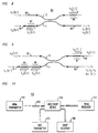
- FIG. 3 schematically illustrates the principle of the invention by means of an exemplary low loss drop multiplex device.
- Device 30 comprises an MDC as shown in FIG. 1.
- Fibers 31 and 32 are single mode fibers
- fibers 33 and 34 are multimode fibers.
- WDM single mode (0,1) radiation ( ⁇ 1 , ⁇ 2 , ...... ⁇ N ) propagates essentially unchanged through the coupling region to fiber 34, which comprises blazed refractive index grating 35.
- Radiation of a predetermined wavelength e.g., ⁇ 1
- a higher order spatial mode e.g., (1,1)
- the (1,1) radiation is coupled into second fiber 12 and propagates towards and into fiber 33, where it is available for utilization, e.g., detection by conventional detector 36, exemplarily a wide area detector capable of collecting substantially all of the higher order mode radiation.
- the grating 35 can be written into fiber 11 downstream of the coupling region (i.e., fiber 34 optionally is continuous with 11), but more typically fiber 34 is spliced to fiber 11.
- FIG. 3 can be readily modified to provide the "dropped" channel ⁇ 1 as (0,1) mode to the utilization means. This is accomplished by replacing multimode fiber 33 by a transmissive MCG that converts ⁇ 1 (1,1) light to ⁇ 1 (0,1) light. If desired, a length of single mode fiber is spliced to the output of the transmissive MCG, and the single mode fiber guides the dropped channel to the utilization means.
- a further exemplary drop multiplex device 50 is shown schematically in FIG. 5.
- Fibers 51, 52 and 53 are single mode fibers, and fibers 11, 12, 54 and 55 are multimode fibers.
- WDM (0,1) radiation ⁇ 1 , ⁇ 2 , Across ⁇ N propagates through fiber 51 to the MDC, with all wavelengths passing through the coupling region to fiber 54.
- Grating 56 is selected to pass all but one of the channels, reflecting the one channel (e.g., ⁇ 1 ) in a higher order mode, e.g., (1,1).
- the higher order mode is coupled into fiber 12, travels in fiber 55 to grating 57, where it is reflected as (0,1) mode.
- the reflected ⁇ 1 (0,1) radiation passes through the MDC in fiber 12 and is available for utilization, e.g., detection, from fiber 53.
- FIG. 6 schematically depicts an exemplary low loss add multiplex device 60.
- Fibers 61, 62 and 63 are single mode fibers, and fibers 11, 12, 64 and 65 are multimode fibers.
- the channel that is to be added propagates through fiber 63 to fiber 12 of the MDC and on to fiber 65.
- Grating 66 reflects ⁇ 1 in a higher order spatial mode, typically (1,1), which is coupled into fiber 11, and propagates to grating 67 in fiber 64, where it is reflected in the (0,1) mode and propagates through fiber 11 to fiber 61.
- Channels ⁇ 2 , .» ⁇ N (all (0,1)) propagate on fiber 62 to fiber 64 and, without mode conversion or significant attenuation, through grating 67 to fiber 11, and on to fiber 61, where channels ⁇ 1 , ⁇ 2 , ......... ⁇ N (all (0,1)) are available for utilization, e.g., transmission to the next node.
- Fibers 71, 72, 73 and 74 are single mode fibers, all other fibers are multimode.
- Channels ⁇ 1 , ⁇ 2 ........ ⁇ N (all (0,1)) enter the device on fiber 71, with channels ⁇ 2 ........ ⁇ N propagating through the device substantially without attenuation, to appear at fiber 74.
- the ⁇ 1 radiation is reflected at grating 75 and transformed into (1,1). It propagates to grating 76, where it is reflected and transformed into (0,1) which propagates to fiber 72, where it is available for detection or other utilization.
- Add channel ⁇ * / 1 (0,1) propagates from fiber 73 to grating 77, where it is reflected in the (1,1) mode.
- the (1,1) radiation propagates to grating 75, where it is reflected and transformed to (0,1), which then propagates to fiber 74, where it is available for utilization, together with ⁇ 2 ?? ⁇ N (all as (0,1)).
- the add channel is designated ⁇ * / 1, to indicate that the wavelength is the same as that of the drop channel, but that the information content is different.
- MDCs will typically comprise two dissimilar multimode fibers, that any fiber that has to carry higher order mode radiation has to be a multimode (typically dual mode) fiber, and that fibers that do not have to carry higher order mode radiation typically are single mode fibers.
- FIG. 8 schematically shows such a power combiner (80), with fibers 83, 84 and 85 being single mode fibers, and all other fibers being multimode fibers.
- ⁇ 1 (0,1) radiation propagates through fiber 85 to fiber 12 and on to grating 86, where it is reflected in a higher order mode, typically (1,1). The radiation then is coupled into fiber 11, propagates to grating 87, where it is reflected in the (0,1) mode and propagates to fiber 83.
- ⁇ 2 ........ (0,1) radiation passes without mode transformation or substantial attenuation through grating 87 to fiber 11 and on to fiber 83, such that ⁇ 1 (0,1) and ⁇ 2 ........ (0,1) are combined and available for utilization.
- FIG. 9 schematically depicts an exemplary triple power combiner.
- Fibers 91, 92, 93 and 94 are single mode fibers, all others are multimode fibers.
- ⁇ 1 (0,1) radiation propagates from fiber 91, through gratings 95 and 96, to output fiber 93.
- ⁇ 2 ........ (0,1) radiation propagates from fiber 92 to grating 97, is reflected as (1,1) mode, is coupled to fiber 11, propagates to grating 95, where it is reflected as (0,1) which propagates to fiber 93.
- ⁇ 3 (1,1) propagates through grating 97, is coupled to fiber 11, propagates to grating 96 where it is reflected as (0,1) and propagates to fiber 93, where all three wavelengths are available as (0,1).
- one of the wavelengths (e.g., ⁇ 3 ) has to be introduced as higher order mode (e.g., (1,1)).
- This is readily achieved, for instance by replacing fiber 94 with a transmissive MCG that transforms ⁇ 3 (0,1) to ⁇ 3 (1,1), or by using as ⁇ 3 source a fiber laser whose output is (1,1).
- ⁇ 1 (0,1) can be replaced by WDM channels ⁇ 1 .» ⁇ N , all (0,1), with the remaining two input ports receiving pump radiation, and with fiber 93 being a rare earth doped amplifier fiber.
- FIG. 10 schematically depicts an exemplary optical waveguide communication system 100 according to the invention.
- WDM transmitter 101 provides light of wavelengths ⁇ 1 , ⁇ 2 ?? ⁇ N , which is coupled into optical waveguide 102 and propagates towards WDM receiver 103.
- add/drop device 104 Between WDM transmitter and receiver is disposed add/drop device 104 according to the invention.
- a desired channel e.g., ⁇ 1
- a desired channel e.g., ⁇ * / 1
- add transmitter 105 e.g., ⁇ * / 1
- the fiber was exposed through a phase mask for 142 seconds to a 3 mm x 0.6 mm FWHM Gaussian beam from an excimer-pumped, frequency-doubled dye laser.
- the laser output was 30 Hz at 242 nm, with a fluence of 25 mJ/pulse/cm 2 , with the 3 mm beam dimension aligned with the axis of the fiber.
- the zero order-nulled phase mask had a period ⁇ 0 of 0.903 ⁇ m.
- the blaze angle is 6°15', and the resulting grating is a (0,1)/(1,1) reflective MCG at about 1340 nm, with essentially no (0,1)/(0,1) reflection at any wavelength within about 10 nm of that wavelength.
- a first and a second dual mode optical fiber is provided.
- the fibers are selected to have essentially equal propagation constant ⁇ 11 at 1340 nm, and to have substantially different propagation constants ⁇ 01 at that wavelength.
- a portion of the cladding of each of the fibers is removed substantially as shown in US patent 4,828,350, and the fibers are assembled such that they are evanescent field-coupled, also substantially as shown in the '350 patent.
- the coupling is selected such that essentially all LP 01 1340 nm radiation propagates straight through the coupler, and such that essentially all LP 11 1340 nm radiation is coupled from one fiber to the other fiber.
- the assembled fibers thus form a MDC.
- the MDC and the MCG are combined substantially as shown in FIG. 3.
- the combination performs the drop function for a 1340 nm channel in a WDM optical communication system.
Landscapes
- Physics & Mathematics (AREA)
- General Physics & Mathematics (AREA)
- Optics & Photonics (AREA)
- Optical Communication System (AREA)
- Optical Integrated Circuits (AREA)
- Optical Fibers, Optical Fiber Cores, And Optical Fiber Bundles (AREA)
Applications Claiming Priority (2)
| Application Number | Priority Date | Filing Date | Title |
|---|---|---|---|
| US712697 | 1991-06-10 | ||
| US08/712,697 US5717798A (en) | 1996-09-12 | 1996-09-12 | Optical waveguide system comprising a mode coupling grating and a mode discrimination coupler |
Publications (2)
| Publication Number | Publication Date |
|---|---|
| EP0829741A2 true EP0829741A2 (de) | 1998-03-18 |
| EP0829741A3 EP0829741A3 (de) | 1998-04-29 |
Family
ID=24863169
Family Applications (1)
| Application Number | Title | Priority Date | Filing Date |
|---|---|---|---|
| EP97306781A Withdrawn EP0829741A3 (de) | 1996-09-12 | 1997-09-02 | System optischer Wellenleiter mit einem Gitter zur Modenkopplung und einem Koppler zur Modenauswahl |
Country Status (3)
| Country | Link |
|---|---|
| US (1) | US5717798A (de) |
| EP (1) | EP0829741A3 (de) |
| JP (1) | JP3377729B2 (de) |
Cited By (1)
| Publication number | Priority date | Publication date | Assignee | Title |
|---|---|---|---|---|
| CN116736441A (zh) * | 2023-05-09 | 2023-09-12 | 西安电子科技大学 | 一种基于高阶模式的反射式集成光谐振结构 |
Families Citing this family (25)
| Publication number | Priority date | Publication date | Assignee | Title |
|---|---|---|---|---|
| US6078709A (en) * | 1997-11-12 | 2000-06-20 | Lucent Technologies Inc. | Method and apparatus for monitoring multi-wavelength optical systems |
| WO2000002085A1 (en) * | 1998-07-01 | 2000-01-13 | Nec Corporation | Matrix optical switch and optical adm |
| US6212318B1 (en) * | 1998-10-22 | 2001-04-03 | Thomas & Betts International, Inc. | Add/drop filters and multiplexers fabricated from cladding mode couplers and fiber bragg gratings |
| IES990137A2 (en) * | 1999-02-22 | 2000-08-23 | Sumicem Opto Electronics Irela | High isolation couplers |
| US6205269B1 (en) * | 1999-04-06 | 2001-03-20 | Ciena Corporation | Optical add/drop multiplexer |
| JP2001267665A (ja) * | 2000-03-16 | 2001-09-28 | Sumitomo Electric Ind Ltd | 光増幅用光ファイバ、光ファイバ増幅器および光ファイバレーザ発振器 |
| US6400865B1 (en) | 2000-05-31 | 2002-06-04 | Fitel Usa Corp. | Article comprising a Bragg grating in a few-moded optical waveguide |
| US6594410B2 (en) | 2000-08-26 | 2003-07-15 | Cidra Corporation | Wide range tunable optical filter |
| US7386204B1 (en) | 2000-08-26 | 2008-06-10 | Cidra Corporation | Optical filter having a shaped filter function |
| JP2002090556A (ja) * | 2000-09-20 | 2002-03-27 | Sumitomo Electric Ind Ltd | 光導波路型回折格子素子、光導波路型回折格子素子製造方法、合分波モジュールおよび光伝送システム |
| US6628859B2 (en) | 2001-03-22 | 2003-09-30 | Triquint Technology Holding Co. | Broadband mode converter |
| US6636666B2 (en) | 2001-05-14 | 2003-10-21 | University Of Iowa Research Foundation | Optical power equalizer |
| TW200404172A (en) * | 2002-08-22 | 2004-03-16 | Showa Electric Wire & Cable Co | Pseudo slant fiber Bragg grating, multiple series fiber Bragg grating, optical fiber type coupler and optical connector |
| FR2856482B1 (fr) * | 2003-06-20 | 2005-11-11 | Cit Alcatel | Filtre optique |
| US7630643B2 (en) * | 2004-08-05 | 2009-12-08 | Panasonic Corporation | Multimode optical transmission system and multimode optical transmission method |
| US7289698B2 (en) * | 2004-11-15 | 2007-10-30 | Analog Devices, Inc. | High bitrate transport over multimode fibers |
| US7215846B1 (en) * | 2004-11-15 | 2007-05-08 | Analog Devices, Inc. | Mode discriminating on-chip optical coupler for an optical receiver connected to dual mode/multimode fiber |
| US7120337B1 (en) * | 2005-03-29 | 2006-10-10 | Avanex Corporation | Fiber optic pigtail design for reducing insertion loss and insertion loss ripple |
| JP4571160B2 (ja) * | 2007-02-27 | 2010-10-27 | 日本電信電話株式会社 | 伝搬モード選択器および光伝送システム |
| JP2013205456A (ja) * | 2012-03-27 | 2013-10-07 | Oki Electric Ind Co Ltd | 波長選択性経路切換素子 |
| JP6300437B2 (ja) * | 2012-09-26 | 2018-03-28 | 沖電気工業株式会社 | 光導波路素子 |
| US20220357516A1 (en) * | 2019-06-21 | 2022-11-10 | Commscope Technologies Llc | Multifiber connector for concentric mutli-core fiber |
| CN113126207B (zh) * | 2019-12-30 | 2025-09-12 | 华为技术有限公司 | 光纤信号模式转换装置、转换方法及光纤传输系统 |
| CN113376743B (zh) * | 2021-06-22 | 2022-12-13 | 电子科技大学 | 一种基于长周期光栅的模斑转换器 |
| US12517302B2 (en) | 2022-11-14 | 2026-01-06 | Corning Incorporated | Mode-selective optical fiber couplers |
Family Cites Families (5)
| Publication number | Priority date | Publication date | Assignee | Title |
|---|---|---|---|---|
| US4986624A (en) * | 1985-07-15 | 1991-01-22 | The Board Of Trustees Of The Leland Stanford Junior University | Optical fiber evanescent grating reflector |
| US4828350A (en) * | 1986-01-17 | 1989-05-09 | The Board Of Trustees Of The Leland Stanford Junior University | Fiber optic mode selector |
| US5104209A (en) * | 1991-02-19 | 1992-04-14 | Her Majesty The Queen In Right Of Canada, As Represented By The Minister Of Communications | Method of creating an index grating in an optical fiber and a mode converter using the index grating |
| US5473714A (en) * | 1994-04-29 | 1995-12-05 | At&T Corp. | Optical fiber system using tapered fiber devices |
| GB9423105D0 (en) * | 1994-11-16 | 1995-01-04 | Northern Telecom Ltd | Optical wave grating filter |
-
1996
- 1996-09-12 US US08/712,697 patent/US5717798A/en not_active Expired - Fee Related
-
1997
- 1997-09-02 EP EP97306781A patent/EP0829741A3/de not_active Withdrawn
- 1997-09-12 JP JP24845397A patent/JP3377729B2/ja not_active Expired - Fee Related
Cited By (1)
| Publication number | Priority date | Publication date | Assignee | Title |
|---|---|---|---|---|
| CN116736441A (zh) * | 2023-05-09 | 2023-09-12 | 西安电子科技大学 | 一种基于高阶模式的反射式集成光谐振结构 |
Also Published As
| Publication number | Publication date |
|---|---|
| EP0829741A3 (de) | 1998-04-29 |
| JP3377729B2 (ja) | 2003-02-17 |
| JPH10104460A (ja) | 1998-04-24 |
| US5717798A (en) | 1998-02-10 |
Similar Documents
| Publication | Publication Date | Title |
|---|---|---|
| US5717798A (en) | Optical waveguide system comprising a mode coupling grating and a mode discrimination coupler | |
| US5457758A (en) | Add-drop device for a wavelength division multiple, fiber optic transmission system | |
| US5093876A (en) | WDM systems incorporating adiabatic reflection filters | |
| US5459801A (en) | Coupler used to fabricate add-drop devices, dispersion compensators, amplifiers, oscillators, superluminescent devices, and communications systems | |
| EP0468715B1 (de) | Adiabatische Reflexionsvorrichtung | |
| US6002822A (en) | Article comprising an optional waveguide tap | |
| US6850665B2 (en) | Wavelength-selective optical fiber components using cladding-mode assisted coupling | |
| US6339665B1 (en) | Apparatus and method for compensation of chromatic dispersion in optical fibers | |
| US6269205B1 (en) | Optical devices based on energy transfer between different modes in optical waveguide | |
| WO2002039146A2 (en) | Wavelength-selective optical fiber components using cladding-mode assisted coupling | |
| EP1064574A1 (de) | Transversaler modenwandler für die optische nachrichtentechnik | |
| US6404952B1 (en) | Optical communication system with chromatic dispersion compensation | |
| KR100311281B1 (ko) | 기울어진 브래그 격자와 모드 분할 방향성 결합기를 이용한 광 파장 가감기 | |
| EP1677131B1 (de) | Optischer Koppler mit Faser-Bragg-Gitter und Fabry-Perot-Kavität entsprechende Methode der Nutzung | |
| Park et al. | All-fiber add-drop wavelength-division multiplexer based on intermodal coupling | |
| USRE35516E (en) | Adiabatic reflection Y-coupler apparatus | |
| EP0779721A2 (de) | Einfügung von Kanälen in einem WDM-System | |
| Åslund et al. | Antisymmetric grating coupler: experimental results | |
| Keiser | Wavelength division multiplexing (WDM) | |
| US6351586B1 (en) | Wavelength dependent phase delay device | |
| KR100438014B1 (ko) | 다중 모드 간섭을 이용한 가변 광필터 | |
| WO1999042871A1 (en) | Optical device | |
| CN1412966A (zh) | 一种光纤色散补偿方法及其装置 |
Legal Events
| Date | Code | Title | Description |
|---|---|---|---|
| PUAI | Public reference made under article 153(3) epc to a published international application that has entered the european phase |
Free format text: ORIGINAL CODE: 0009012 |
|
| PUAL | Search report despatched |
Free format text: ORIGINAL CODE: 0009013 |
|
| AK | Designated contracting states |
Kind code of ref document: A2 Designated state(s): DE FR GB IT |
|
| RHK1 | Main classification (correction) |
Ipc: G02B 6/16 |
|
| AK | Designated contracting states |
Kind code of ref document: A3 Designated state(s): AT BE CH DE DK ES FI FR GB GR IE IT LI LU MC NL PT SE |
|
| 17P | Request for examination filed |
Effective date: 19981015 |
|
| AKX | Designation fees paid |
Free format text: DE FR GB IT |
|
| RBV | Designated contracting states (corrected) |
Designated state(s): DE FR GB IT |
|
| STAA | Information on the status of an ep patent application or granted ep patent |
Free format text: STATUS: THE APPLICATION HAS BEEN WITHDRAWN |
|
| 18W | Application withdrawn |
Effective date: 20030212 |