EP0829762A1 - Appareil pour le développement de matériau photographique - Google Patents
Appareil pour le développement de matériau photographique Download PDFInfo
- Publication number
- EP0829762A1 EP0829762A1 EP96810611A EP96810611A EP0829762A1 EP 0829762 A1 EP0829762 A1 EP 0829762A1 EP 96810611 A EP96810611 A EP 96810611A EP 96810611 A EP96810611 A EP 96810611A EP 0829762 A1 EP0829762 A1 EP 0829762A1
- Authority
- EP
- European Patent Office
- Prior art keywords
- wall
- shells
- shell
- developed
- bodies
- Prior art date
- Legal status (The legal status is an assumption and is not a legal conclusion. Google has not performed a legal analysis and makes no representation as to the accuracy of the status listed.)
- Granted
Links
- 239000000463 material Substances 0.000 title claims abstract description 13
- 238000006073 displacement reaction Methods 0.000 claims abstract description 32
- 239000007788 liquid Substances 0.000 claims description 24
- 238000000034 method Methods 0.000 claims description 17
- 238000011161 development Methods 0.000 claims description 16
- 230000003014 reinforcing effect Effects 0.000 claims description 8
- 238000003780 insertion Methods 0.000 claims description 2
- 230000037431 insertion Effects 0.000 claims description 2
- 239000012530 fluid Substances 0.000 abstract description 4
- 238000007373 indentation Methods 0.000 abstract 1
- 230000018109 developmental process Effects 0.000 description 15
- 238000004519 manufacturing process Methods 0.000 description 14
- 238000003466 welding Methods 0.000 description 3
- 238000004026 adhesive bonding Methods 0.000 description 2
- 238000003801 milling Methods 0.000 description 2
- 239000000126 substance Substances 0.000 description 2
- 230000009286 beneficial effect Effects 0.000 description 1
- 238000012822 chemical development Methods 0.000 description 1
- 238000013461 design Methods 0.000 description 1
- 239000004033 plastic Substances 0.000 description 1
- 238000012545 processing Methods 0.000 description 1
- 239000002904 solvent Substances 0.000 description 1
- 238000005728 strengthening Methods 0.000 description 1
- 229920001169 thermoplastic Polymers 0.000 description 1
- 239000004416 thermosoftening plastic Substances 0.000 description 1
Images


Classifications
-
- G—PHYSICS
- G03—PHOTOGRAPHY; CINEMATOGRAPHY; ANALOGOUS TECHNIQUES USING WAVES OTHER THAN OPTICAL WAVES; ELECTROGRAPHY; HOLOGRAPHY
- G03D—APPARATUS FOR PROCESSING EXPOSED PHOTOGRAPHIC MATERIALS; ACCESSORIES THEREFOR
- G03D3/00—Liquid processing apparatus involving immersion; Washing apparatus involving immersion
- G03D3/08—Liquid processing apparatus involving immersion; Washing apparatus involving immersion having progressive mechanical movement of exposed material
- G03D3/13—Liquid processing apparatus involving immersion; Washing apparatus involving immersion having progressive mechanical movement of exposed material for long films or prints in the shape of strips, e.g. fed by roller assembly
- G03D3/132—Liquid processing apparatus involving immersion; Washing apparatus involving immersion having progressive mechanical movement of exposed material for long films or prints in the shape of strips, e.g. fed by roller assembly fed by roller assembly
Definitions
- the invention relates to a device for developing photographic material according to the preamble of the independent claim.
- exposed films When processing customer orders in photographic development laboratories, exposed films, usually negative films, are usually first developed wet-chemically and the developed image fields are then copied onto photographic copying material, usually onto photographic paper, by exposure. The exposed photo paper is then also developed by wet chemistry. If the photo paper is available as a long tape, as is customary in high-performance laboratories, the tape is then cut into individual pictures, the individual components of an order are put together and packaged so that they can ultimately be returned to the client.
- the devices which contain the baths for wet chemical development are known as so-called film processors or paper processors.
- the volume of such wet chemical baths in the processors - for the sake of simplicity only paper processors are discussed below - depends essentially on the throughput (number of images developed per unit of time) the respective user, usually development laboratories, would like to achieve.
- the distance through the paper processor must be correspondingly long so that as many images as possible can be in the paper processor at the same time, and with continuous transport on the one hand and relatively fast transport speed on the other hand the throughput time of the paper through the paper processor corresponds to the time required for development (this is given). This results in relatively large-volume baths and therefore also large-volume paper processors.
- Paper processors with low-volume baths have already been proposed to avoid the large-volume baths or processors, for example in US Pat. No. 5,179,404; US-A-5,309,191; US-A-5,311,235 or in US-A-5,270,762.
- the low-volume bathrooms in particular have to be renewed or supplemented from time to time.
- a lively movement of the wet chemical baths in the paper processor has proven to be advantageous, since fresh developing liquid always comes into contact with the paper to be developed in this way. It is obvious that in the case of bathrooms with a lower volume, the baths must be replaced or supplemented at shorter intervals than in the case of larger bathrooms.
- Low-volume baths and thus also comparatively low-volume processors generally have a very narrow channel, which extends from the inlet through the interior of the processor to the outlet and along which the photo paper to be developed is transported. During the transport along this channel, the photo paper to be developed comes into contact with the developing liquid and is thereby developed. Due to the small volume of the channel on the one hand and the requirement for constant circulation of the developing liquid on the other hand, a comparatively high pressure is created in the channel.
- the processors In order to withstand this high pressure, the processors must be mechanically highly stable. At the same time, they should also ensure safe operation. First and foremost, this means that there should be no paper jams in the processors, so it must be ensured that the paper is transported safely along the channel. In addition, the processors should be simple to manufacture and inexpensive to manufacture.
- the device according to the invention thus comprises two half-shells which can be connected to one another, each half-shell of which in turn comprises two plates which are connected to one another. These are assembled into a half-shell and thus one plate forms the outer wall of the half-shell and the other the inner wall of the half-shell. Furthermore, the device according to the invention comprises a central displacement element which, after being introduced into the interconnected half-shells, together with the respective inner wall of the half-shells, the channel for the photographic material to be developed Are defined. This channel extends between the displacement element and the respective inner wall of the half-shell.
- This inner wall of the half-shell is essentially designed as a flat surface, while the outer wall has means for reinforcing the inner wall to prevent deformation of the inner wall due to the high pressure of the developing liquid.
- Such devices are mechanically highly stable, simple and inexpensive to manufacture and reliable in operation.
- the means for reinforcing the inner wall of the half-shell are designed as depressions of the plate forming the outer wall which point towards the inner wall. These depressions are connected at their respective contact surfaces to the plate forming the inner wall.
- the two half-shells have the same shape. This means that practically only one form is required for the production of the half-shells, which further reduces the manufacturing effort.
- the half-shells are produced using the "twin-sheet method". This method allows such half-shells to be produced in a simple manner.
- the displacement element is likewise formed from two half bodies which can be connected to one another.
- Each half body includes two interconnected plates which are joined together to form a half body, in such a way that one plate forms the outer wall of the half body and the other plate the inner wall of the half body.
- the outer wall of the half-body is essentially designed as a flat surface, while the inner wall has means for strengthening the outer wall to prevent deformation of the outer wall due to the high pressure of the developing liquid.
- This design of the displacement element also ensures high mechanical stability, the displacement elements are simple to manufacture and ensure high operational reliability.
- the means for reinforcing the outer wall of the half-body are designed as depressions of the plate forming the inner wall that point towards the outer wall. At their respective contact surface with the plate forming the outer wall, the depressions of the plate forming the inner wall are connected to the plate forming the outer wall.
- the two half-bodies particularly preferably have the same shape, which facilitates the production of the half-bodies since only one shape is required.
- a device in which the two half-bodies are produced by the twin-sheet method is particularly preferred because this method enables such half-bodies to be produced in a simple manner in terms of production technology.
- FIG. 1 shows a basic illustration of an arrangement of a processor with a low-volume development liquid bath.
- Fig. 1 is only intended to illustrate the basic functional principle. Some essential features of the device according to the invention are not shown in FIG. 1.
- 1 shows a tank 1 in which two so-called racks 2 are introduced.
- a narrow channel 3 is defined between the respective inner wall of the tank 1 and the respective outer wall of the rack 2, through which the material to be developed, in the case of a paper processor the photo paper P, is transported and developed through contact with the developing liquid.
- 1 is in the form of a long belt, as is customary in high-performance laboratories, and is transported through channel 3 to outlet A through an inlet E using the drivable rollers R, which also tension the paper belt.
- the development liquid bath in such processors is significantly smaller in volume than in conventional processors in which practically the entire interior of the processor is filled with development liquid, that is to say the development liquid bath is large in volume.
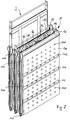
- FIG. 2 shows an embodiment of a device according to the invention in a more or less assembled state in a perspective view. Some details are not yet clearly recognizable from FIG. 2, too, but become clearer with the help of the explanation of the following drawing figures.
- 2 shows three tanks 1 connected in series. Transport rollers R1, R2, R3, R4 for four strips of photo paper are arranged between two adjacent tanks.
- a further roller LR1 for a first - preferably endlessly rotating - leader belt (not shown) is arranged between the transport rollers R1 and R2 and between the transport rollers R3 and R4 a further role LR2 for a second leader band (also not shown).
- the rollers R1, R2, R3, R4 for the photo paper and the rollers LR1 and LR2 for the leader tape, which are arranged between two tanks 1 connected in series, can be driven by means of a conventional, common chain drive (not shown).
- the tapes of the photo paper (not shown) which are guided over the transport rollers R1 and R2 are each fastened by means of a clip to the leader tape which is guided over the roller LR1.
- the clip is stripped again after threading the photo paper.
- the course of the leader band can be imagined as indicated in FIG. 1.
- the leader tape runs practically the same as the photo paper P, but parallel to it. Outside the tank, the leader tape is returned, as indicated by the broken line in FIG. 1, and runs in operation as an endless tape through tank 1 and back again, while the tape of photo paper P is no longer returned after it has passed through tank 1 .
- FIG. 2 also shows that a displacement element, a so-called rack 2, is introduced into the tank 1 (as already explained with reference to FIG. 1). No such rack 2 has yet been introduced in the front tank of FIG. 2, however, in the middle tank it is already shown in the inserted position and in the rear tank it is still shown half pulled out. 2 also shows, particularly in the case of the front tank, that the tank 1 comprises two half-shells 10 and 11 which are connected to one another and thus form the tank 1. On the outer wall 100 of the half-shell 10, several depressions 101 can be seen, which are distributed over the entire outer wall 100 of the half-shell 10. These depressions 101 serve to increase the mechanical stability of the half-shell 10, but they will be discussed in more detail.
- three recesses 102 running in the transverse direction can be seen, into which fastening elements (for example rail-like elements) can be introduced, which encompass the entire processor (virtually clasp the processor) and thus additionally hold it together and thereby further increase the mechanical stability of the processor .
- fastening elements for example rail-like elements
- the entire processor virtually clasp the processor
- three connecting pieces 103 for the supply or removal of developing liquid can also be seen.
- a sleeve 104 through which after insertion of the rack 2 in the tank 1, a fastening element can be passed, with which the rack 2 is fixed in the tank 1.
- Fig. 3 shows an embodiment of a displacement element or rack 2 in the not yet fully assembled state.
- the rack 2 comprises two side bars 22 and 23, and a plurality of rods or tubes 24, 25, 26 and 27 connecting the side bars 22 and 23.
- On the lower bar 27 are the rolls for the bands of photo paper and for the respective one Leader band provided. They are freely rotating on this rod 27.
- the displacement body which comprises two half-bodies 20 and 21 (not yet recognizable in FIG. 3), is pushed over the rods 25 and 26, and the side rail 23 is then firmly connected to the rods 24 and 27.
- the displacement body comprising the two half bodies 20 and 21 has, as can be seen from FIG. 3, a plurality of slots 201, which can be seen on the outer wall 200 of the displacement body.
- the slots 201 are used so that from the interior of the displacement body through these slots 201 the developing paper is practically acted upon as if through a nozzle, which on the one hand counteracts adherence of the photographic paper to the displacing body and on the other hand promotes good circulation of the developing liquid.
- slots 201 are provided in the regions of the outer wall 200 of the displacement body, in which slots the photo paper to be developed is guided.
- Both the half-shells 10 and 11 of the tank 1 and the half-bodies 20 and 21 of the displacement element or rack 2 are preferably produced with the aid of the so-called twin-sheet method, so they are - as the name of the method already says - double-walled and made manufactured two plastic plates. How the individual half-shells 10 and 11 or the half-bodies 20 and 21 look more precisely in terms of their shape will be explained further below. First of all, the basic functioning of the twin-sheet method is to be briefly explained, with the aid of FIGS. 5 and 6.
- FIGS. 5 and 6 The essential steps of the twin-sheet method can be seen in FIGS. 5 and 6.
- two preheated thermoplastic sheets P1 and P2 are placed between the mold halves F1 and F2 (FIG. 5) and heated from the outside until they are completely plasticized.
- the mold halves F1 and F2 are then moved together, and the plasticized plates P1 and P2 are vacuum-deep drawn in one step with the aid of vacuum NP and, at the same time, welded to one another at the edges with high strength (FIG. 6).
- a narrow needle nozzle NJ can be used to generate excess pressure between the plates P1 and P2 by supplying compressed air PP.
- This compressed air PP presses the plates from the inside in addition to the suction generated from the outside by the vacuum NP against the mold halves F1 and F2, whereby the high level of detail is achieved.
- twin-sheet process there is no need for the two parts to be joined afterwards, which means that solvents, welding consumables etc. are no longer necessary. Any material that protrudes from the edge can be removed mechanically (e.g. by milling).
- this method can also be used to produce both the half-shells 10 and 11 of the tank 1 of the device according to the invention and to produce the half-bodies 20 and 21 of the displacement element or rack 2.
- the two half-shells 10 and 11 of the tank 1 and the two half-bodies 20 and 21 of the rack 2 each have the same shape. In this case, only one shape is required in each case for the production of the tank 1 and for the production of the displacement body of the rack 2.
- a half shell, for example half shell 10, of tank 1 can now be seen in section in FIG. 7.
- the half-shell 10 is made from two plates.
- the outer wall 100 of the half-shell 10 is formed by a plate which has a plurality of depressions 101 (see also FIG. 2).
- the inner wall 105 is also formed by a plate.
- the depressions 101 which are provided on the plate forming the outer wall 100, point to the inner wall 105 and are connected at their contact surface to the plate forming the inner wall 105.
- the depressions 101 thus act as a means of reinforcing the plate forming the inner wall 105, thus considerably increasing the mechanical stability.
- the transverse depressions 102 can also be seen (see also FIG. 2), which can accommodate additional fastening elements which encompass the entire processor.
- the inner wall 105 is essentially designed as a flat surface.
- this flat surface is preferably structured, that is to say it has a structure on its surface, which makes it difficult for the photographic paper to adhere to this surface.
- the otherwise essentially flat surface has a region 106 curved in the shape of a segment of a circle.
- this area After the rack 2 has been inserted into the tank 1, the rollers provided at the lower end of the rack 2 for the tapes of the photo paper and for the leader tapes are arranged. Below this area 106, a quasi-cuboid area 107 can also be seen, which opens into the connecting piece 103 (FIG.
- both half-shells 10 and 11 have the same shape, they are made with only one shape. After the two half-shells 10 and 11 have been produced, they are connected to one another and form the tank 1.
- the two half-shells can be connected by means of known methods such as welding, gluing, etc.
- a half body of the displacement element or rack 2 can now be seen in one view.
- this is the half body 20.
- slots 201 are provided in the wall of the half body. Through these slits 201, developing liquid can be pressed against the paper in operation like a nozzle, which on the one hand counteracts a sticking of the paper on the displacement body, on the other hand a circulation of the developing liquid is beneficial.
- Such slots are consequently not provided in the longitudinally extending recess 202 in which the leader tape runs.
- the displacement body 8 is also shown interrupted in FIG. 8, but it can be seen that the side facing the viewer essentially forms a flat surface.
- the flat surface is preferably structured, which counteracts any possible adhesion of the photo paper to this surface.
- the two half-bodies 20 and 21 are also preferably produced using the twin-sheet method already explained.
- FIGS. 9 and 10 represent a section along the line IX-IX or along the line X-X of FIG. 8. 9 that the plate of the half-body 20 forming the outer wall 200 essentially forms a flat (preferably structured) surface which faces the photo paper during operation.
- the plate forming the inner wall 203 is provided with depressions 204 which extend as far as the outer wall 200 and are connected at their contact surface to the outer wall 200, similarly to the case with the half-shells of the tank 1.
- These depressions 204 just as the depressions 101 (FIG. 2) increase the mechanical stability of the half-shell 10, increase the mechanical stability of the half-body 20.
- FIG. 9 and FIG. 10 two transverse ones can be seen on the inner wall 203 Wells 205.
- Both half-bodies 20 and 21 preferably have the same shape, so that only one shape is required for producing the half-bodies.
- the two half bodies 20 and 21 are connected to one another by means of known methods such as welding, gluing, etc., and thus form the displacement body of the rack 2.
- the transverse recesses 205 come to lie opposite one another so that the Displacement body after connecting the two half-bodies 20 and 21 can then be pushed onto the rods 25 and 26 (Fig. 3) and thus the rack 2 can be completed.
- the rods 25 and 26 (FIG. 3) can be provided as hollow cylindrical tubes with corresponding through openings, so that development fluid through the tubes and through their through openings through the slots 201 of the Displacement body can get against the photo paper.
- the slots 201 are not yet present in the production of the half bodies 20 and 21, they have to be produced in a separate working step either on the half bodies before connecting to the displacement body or on the finished displacement body, for example by milling.
- the rack 2 is then introduced into the tank 1.
- several such devices are usually arranged one behind the other, as is the case, for example, is indicated in Fig. 2, where three such devices are arranged one behind the other, there may of course be more than three devices, which is usually the case with high-performance laboratories.
Landscapes
- Physics & Mathematics (AREA)
- General Physics & Mathematics (AREA)
- Photographic Processing Devices Using Wet Methods (AREA)
Priority Applications (3)
| Application Number | Priority Date | Filing Date | Title |
|---|---|---|---|
| DE59610049T DE59610049D1 (de) | 1996-09-13 | 1996-09-13 | Vorrichtung zum Entwickeln von fotografischem Material |
| EP96810611A EP0829762B1 (fr) | 1996-09-13 | 1996-09-13 | Appareil pour le développement de matériau photographique |
| US08/926,480 US5870646A (en) | 1996-09-13 | 1997-09-10 | Apparatus for developing photographic material |
Applications Claiming Priority (1)
| Application Number | Priority Date | Filing Date | Title |
|---|---|---|---|
| EP96810611A EP0829762B1 (fr) | 1996-09-13 | 1996-09-13 | Appareil pour le développement de matériau photographique |
Publications (2)
| Publication Number | Publication Date |
|---|---|
| EP0829762A1 true EP0829762A1 (fr) | 1998-03-18 |
| EP0829762B1 EP0829762B1 (fr) | 2003-01-08 |
Family
ID=8225697
Family Applications (1)
| Application Number | Title | Priority Date | Filing Date |
|---|---|---|---|
| EP96810611A Expired - Lifetime EP0829762B1 (fr) | 1996-09-13 | 1996-09-13 | Appareil pour le développement de matériau photographique |
Country Status (3)
| Country | Link |
|---|---|
| US (1) | US5870646A (fr) |
| EP (1) | EP0829762B1 (fr) |
| DE (1) | DE59610049D1 (fr) |
Cited By (1)
| Publication number | Priority date | Publication date | Assignee | Title |
|---|---|---|---|---|
| EP0859279A1 (fr) * | 1997-02-14 | 1998-08-19 | Eastman Kodak Company | Dispositif d'insertion |
Citations (4)
| Publication number | Priority date | Publication date | Assignee | Title |
|---|---|---|---|---|
| US4577951A (en) * | 1983-09-28 | 1986-03-25 | Fuji Photo Film Co., Ltd. | Processing solution tank with hinged sections |
| DE3536862A1 (de) * | 1985-10-16 | 1987-04-16 | Agfa Gevaert Ag | Zum einsetzen eines racks geeigneter behandlungstank fuer fotografisches material |
| US5179404A (en) * | 1992-03-02 | 1993-01-12 | Eastman Kodak Company | Anti-web adhering contour surface for a photographic processing apparatus |
| EP0623849A1 (fr) * | 1993-05-03 | 1994-11-09 | Eastman Kodak Company | Appareils de développement automatiques |
Family Cites Families (5)
| Publication number | Priority date | Publication date | Assignee | Title |
|---|---|---|---|---|
| DE3614253C1 (de) * | 1986-04-26 | 1987-08-27 | Agfa Gevaert Ag | Verfahren und Vorrichtung zur Entwicklung von fotografischem Material |
| GB9003282D0 (en) * | 1990-02-14 | 1990-04-11 | Kodak Ltd | Method and apparatus for photographic processing |
| US5309191A (en) * | 1992-03-02 | 1994-05-03 | Eastman Kodak Company | Recirculation, replenishment, refresh, recharge and backflush for a photographic processing apparatus |
| US5311235A (en) * | 1992-03-02 | 1994-05-10 | Eastman Kodak Company | Driving mechanism for a photographic processing apparatus |
| US5270762A (en) * | 1992-03-02 | 1993-12-14 | Eastman Kodak Company | Slot impingement for a photographic processing apparatus |
-
1996
- 1996-09-13 EP EP96810611A patent/EP0829762B1/fr not_active Expired - Lifetime
- 1996-09-13 DE DE59610049T patent/DE59610049D1/de not_active Expired - Fee Related
-
1997
- 1997-09-10 US US08/926,480 patent/US5870646A/en not_active Expired - Fee Related
Patent Citations (4)
| Publication number | Priority date | Publication date | Assignee | Title |
|---|---|---|---|---|
| US4577951A (en) * | 1983-09-28 | 1986-03-25 | Fuji Photo Film Co., Ltd. | Processing solution tank with hinged sections |
| DE3536862A1 (de) * | 1985-10-16 | 1987-04-16 | Agfa Gevaert Ag | Zum einsetzen eines racks geeigneter behandlungstank fuer fotografisches material |
| US5179404A (en) * | 1992-03-02 | 1993-01-12 | Eastman Kodak Company | Anti-web adhering contour surface for a photographic processing apparatus |
| EP0623849A1 (fr) * | 1993-05-03 | 1994-11-09 | Eastman Kodak Company | Appareils de développement automatiques |
Cited By (2)
| Publication number | Priority date | Publication date | Assignee | Title |
|---|---|---|---|---|
| EP0859279A1 (fr) * | 1997-02-14 | 1998-08-19 | Eastman Kodak Company | Dispositif d'insertion |
| US5980130A (en) * | 1997-02-14 | 1999-11-09 | Eastman Kodak Company | Rack |
Also Published As
| Publication number | Publication date |
|---|---|
| EP0829762B1 (fr) | 2003-01-08 |
| US5870646A (en) | 1999-02-09 |
| DE59610049D1 (de) | 2003-02-13 |
Similar Documents
| Publication | Publication Date | Title |
|---|---|---|
| DE2617479B2 (de) | Papiertransporteinrichtung in einem kopiergeraet | |
| DE69719181T2 (de) | Aufgerollte taschen und verfahren und vorrichtung zum herstellen von endlos aufgerollten taschen | |
| DE3345084C2 (de) | Entwicklungsvorrichtung für horizontal geführte Schichtträger | |
| DE3236845C2 (de) | Verfahren zum automatischen Schneiden von Filmstreifen | |
| DE2220397A1 (de) | Automatische Diazo-Kopiermaschme mit Rollenförderung | |
| DE69118667T2 (de) | Verfahren und Vorrichtung zum Anbringen von Verbindungsstellen-Anzeigelöchern in Fotopapier | |
| EP0829762B1 (fr) | Appareil pour le développement de matériau photographique | |
| DE69304410T2 (de) | Entwicklungsgerät | |
| DE2638260A1 (de) | Blattzufuehreinrichtung | |
| DE2638605A1 (de) | Farbband-stopfkassette | |
| DE2141396A1 (de) | Gerät zur Behandlung von biegsamem Material mit einer Arbeitslösung | |
| DE4132717A1 (de) | Vorrichtung zum aufbringen eines klebers auf blattfoermiges material | |
| DE2124230C3 (de) | Vorrichtung zum Transportieren und Stapeln von blattförmigen Aufzeichnungsträgern | |
| EP0479038B1 (fr) | Cadre d'images pour guider les bandes de film exposé et développé | |
| DE2528855A1 (de) | Auftragvorrichtung | |
| DE69409158T2 (de) | Papiermaske | |
| EP0791854B1 (fr) | Appareil pour le développement de matériel photographique en forme de feuille ou de bande | |
| DE3007406A1 (de) | Einrichtung fuer einen vorlagenumlauf in einem kopiergeraet | |
| DE69516439T2 (de) | Entwicklungsgerät | |
| DE2320163C2 (de) | Kassette für integrale selbstentwickelnde Filmeinheiten | |
| DE3919279A1 (de) | Verpackungseinheit | |
| DE2707448A1 (de) | Verfahren zum aendern der fortbewegungsrichtung von blaettern | |
| DE69317151T2 (de) | Photographisches Entwicklungsgerät mit spiralförmigem Transportweg | |
| DE2244706C3 (de) | Verfahren und Vorrichtung zur Herstellung von Diarähmchen | |
| DE60035761T2 (de) | Optischer printer |
Legal Events
| Date | Code | Title | Description |
|---|---|---|---|
| PUAI | Public reference made under article 153(3) epc to a published international application that has entered the european phase |
Free format text: ORIGINAL CODE: 0009012 |
|
| AK | Designated contracting states |
Kind code of ref document: A1 Designated state(s): CH DE FR GB IT LI |
|
| 17P | Request for examination filed |
Effective date: 19980820 |
|
| AKX | Designation fees paid |
Free format text: CH DE FR GB IT LI |
|
| RBV | Designated contracting states (corrected) |
Designated state(s): CH DE FR GB IT LI |
|
| GRAH | Despatch of communication of intention to grant a patent |
Free format text: ORIGINAL CODE: EPIDOS IGRA |
|
| GRAH | Despatch of communication of intention to grant a patent |
Free format text: ORIGINAL CODE: EPIDOS IGRA |
|
| GRAA | (expected) grant |
Free format text: ORIGINAL CODE: 0009210 |
|
| 111Z | Information provided on other rights and legal means of execution |
Free format text: 20021022 CH DE FR GB IT LI |
|
| AK | Designated contracting states |
Kind code of ref document: B1 Designated state(s): CH DE FR GB IT LI |
|
| REG | Reference to a national code |
Ref country code: GB Ref legal event code: FG4D Free format text: NOT ENGLISH |
|
| REG | Reference to a national code |
Ref country code: CH Ref legal event code: EP |
|
| GBT | Gb: translation of ep patent filed (gb section 77(6)(a)/1977) |
Effective date: 20030108 |
|
| REF | Corresponds to: |
Ref document number: 59610049 Country of ref document: DE Date of ref document: 20030213 Kind code of ref document: P |
|
| ET | Fr: translation filed | ||
| PGFP | Annual fee paid to national office [announced via postgrant information from national office to epo] |
Ref country code: GB Payment date: 20030916 Year of fee payment: 8 |
|
| PGFP | Annual fee paid to national office [announced via postgrant information from national office to epo] |
Ref country code: FR Payment date: 20030919 Year of fee payment: 8 Ref country code: CH Payment date: 20030919 Year of fee payment: 8 |
|
| PGFP | Annual fee paid to national office [announced via postgrant information from national office to epo] |
Ref country code: DE Payment date: 20030925 Year of fee payment: 8 |
|
| PLBE | No opposition filed within time limit |
Free format text: ORIGINAL CODE: 0009261 |
|
| STAA | Information on the status of an ep patent application or granted ep patent |
Free format text: STATUS: NO OPPOSITION FILED WITHIN TIME LIMIT |
|
| 26N | No opposition filed |
Effective date: 20031009 |
|
| PG25 | Lapsed in a contracting state [announced via postgrant information from national office to epo] |
Ref country code: GB Free format text: LAPSE BECAUSE OF NON-PAYMENT OF DUE FEES Effective date: 20040913 |
|
| PG25 | Lapsed in a contracting state [announced via postgrant information from national office to epo] |
Ref country code: LI Free format text: LAPSE BECAUSE OF NON-PAYMENT OF DUE FEES Effective date: 20040930 Ref country code: CH Free format text: LAPSE BECAUSE OF NON-PAYMENT OF DUE FEES Effective date: 20040930 |
|
| PG25 | Lapsed in a contracting state [announced via postgrant information from national office to epo] |
Ref country code: DE Free format text: LAPSE BECAUSE OF NON-PAYMENT OF DUE FEES Effective date: 20050401 |
|
| GBPC | Gb: european patent ceased through non-payment of renewal fee |
Effective date: 20040913 |
|
| REG | Reference to a national code |
Ref country code: CH Ref legal event code: PL |
|
| PG25 | Lapsed in a contracting state [announced via postgrant information from national office to epo] |
Ref country code: FR Free format text: LAPSE BECAUSE OF NON-PAYMENT OF DUE FEES Effective date: 20050531 |
|
| REG | Reference to a national code |
Ref country code: CH Ref legal event code: AUV Free format text: DAS OBGENANNTE PATENT IST, MANGELS BEZAHLUNG DER 09. JAHRESGEBUEHR, INNERT DER GESETZLICHEN FRIST, DURCH VERFUEGUNG VOM 30. APRIL 2005 ERLOSCHEN. DIE VERFUEGUNG KONNTE DEM PATENTINHABER NICHT ZUGESTELLT WERDEN. |
|
| REG | Reference to a national code |
Ref country code: FR Ref legal event code: ST |
|
| PG25 | Lapsed in a contracting state [announced via postgrant information from national office to epo] |
Ref country code: IT Free format text: LAPSE BECAUSE OF NON-PAYMENT OF DUE FEES;WARNING: LAPSES OF ITALIAN PATENTS WITH EFFECTIVE DATE BEFORE 2007 MAY HAVE OCCURRED AT ANY TIME BEFORE 2007. THE CORRECT EFFECTIVE DATE MAY BE DIFFERENT FROM THE ONE RECORDED. Effective date: 20050913 |