EP0829800A2 - Koordinateneingabevorrichtung - Google Patents
Koordinateneingabevorrichtung Download PDFInfo
- Publication number
- EP0829800A2 EP0829800A2 EP97115001A EP97115001A EP0829800A2 EP 0829800 A2 EP0829800 A2 EP 0829800A2 EP 97115001 A EP97115001 A EP 97115001A EP 97115001 A EP97115001 A EP 97115001A EP 0829800 A2 EP0829800 A2 EP 0829800A2
- Authority
- EP
- European Patent Office
- Prior art keywords
- phase
- signal
- color
- coordinate input
- tablet
- Prior art date
- Legal status (The legal status is an assumption and is not a legal conclusion. Google has not performed a legal analysis and makes no representation as to the accuracy of the status listed.)
- Granted
Links
Images


Classifications
-
- G—PHYSICS
- G06—COMPUTING OR CALCULATING; COUNTING
- G06F—ELECTRIC DIGITAL DATA PROCESSING
- G06F3/00—Input arrangements for transferring data to be processed into a form capable of being handled by the computer; Output arrangements for transferring data from processing unit to output unit, e.g. interface arrangements
- G06F3/01—Input arrangements or combined input and output arrangements for interaction between user and computer
- G06F3/048—Interaction techniques based on graphical user interfaces [GUI]
- G06F3/0487—Interaction techniques based on graphical user interfaces [GUI] using specific features provided by the input device, e.g. functions controlled by the rotation of a mouse with dual sensing arrangements, or of the nature of the input device, e.g. tap gestures based on pressure sensed by a digitiser
- G06F3/0488—Interaction techniques based on graphical user interfaces [GUI] using specific features provided by the input device, e.g. functions controlled by the rotation of a mouse with dual sensing arrangements, or of the nature of the input device, e.g. tap gestures based on pressure sensed by a digitiser using a touch-screen or digitiser, e.g. input of commands through traced gestures
-
- G—PHYSICS
- G06—COMPUTING OR CALCULATING; COUNTING
- G06F—ELECTRIC DIGITAL DATA PROCESSING
- G06F3/00—Input arrangements for transferring data to be processed into a form capable of being handled by the computer; Output arrangements for transferring data from processing unit to output unit, e.g. interface arrangements
- G06F3/01—Input arrangements or combined input and output arrangements for interaction between user and computer
- G06F3/03—Arrangements for converting the position or the displacement of a member into a coded form
- G06F3/033—Pointing devices displaced or positioned by the user, e.g. mice, trackballs, pens or joysticks; Accessories therefor
- G06F3/0354—Pointing devices displaced or positioned by the user, e.g. mice, trackballs, pens or joysticks; Accessories therefor with detection of two-dimensional [2D] relative movements between the device, or an operating part thereof, and a plane or surface, e.g. 2D mice, trackballs, pens or pucks
- G06F3/03545—Pens or stylus
Definitions
- the present invention relates to a coordinate input device that is applicable to computers for processing handprinted characters, graphics, etc., and also concerns a program-recording medium used for such a device.
- Coordinate input devices have an input-use panel called a tablet, and a certain position on this panel is specified by means of a pen, a mouse, etc., so that the coordinates of the specified position is inputted. Moreover, some coordinate input devices are provided with a display panel such as an LCD on the under-surface of the tablet, and the position of the inputted coordinates are displayed on the display panel.
- a display panel such as an LCD on the under-surface of the tablet
- a conventional coordinate input device having a color display means is normally provided with a color-selection means on the tablet side, which selects display colors, and selection is made from a limited number of colors displayed on the tablet by means of a pen, a mouse, etc.
- Japanese Laid-Open Patent Publication No. 177518/1992 discloses a construction wherein a switch for selecting display colors is installed on the pen side.
- Japanese Laid-Open Patent Publication No. 115154/1996 discloses a construction wherein: a magnetic field having a certain intensity is generated among plurality of magnetic fields having mutually different intensities, and display is made by using a color corresponding to the intensity of the magnetic field.
- selectable colors are preliminarily set in a fixed and limited manner, and even if the user desires a half-tone color or color that is subtly different from any of the set colors, he or she has to select a color that is close to the desired color among the set colors. Therefore, these arrangements have failed to display half-tone colors or colors that are subtly different from set colors.
- the first objective of the present invention is to provide a coordinate input device which is capable of inputting virtually limitless colors upon making a selection of colors and displaying even half-tone colors and colors that are subtly different from each other.
- the second objective of the present invention is to provide a coordinate input device which is capable of changing and resetting display colors with a simple operation.
- the third objective of the present invention is to provide a program-recording medium that carries out necessary processes for such a coordinate input device.
- the coordinate input device of the present invention which detects a signal outputted from a coordinate input pen on the surface of a tablet and converts it into coordinate data, is provided with: a phase-conversion means for shifting the phase of an ac signal from the device main body and for outputting the resulting signal to the coordinate input pen; an amplification means for amplifying the ac signal with its phase changed that was outputted from the coordinate input pen and has been detected on the tablet surface; a phase-difference detection means for detecting the phase difference between the signal amplified by the amplification means and the ac signal from the device main body; and a color conversion means for outputting, together with coordinate data, a specific piece of color information that corresponds to the phase difference that has been detected by the phase-difference detection means from pieces of color information that have been preliminarily stored in association with phase differences.
- display colors can be set and changed to virtually limitless kinds of colors by converting phase differences into colors by the use of a simple operation.
- the coordinate input device prefferably incorporate the phase-conversion means into the coordinate input pen. With this arrangement, the user can specify colors easily by carrying out the color-setting operations on the pen side.
- the coordinate input device prefferably has an arrangement wherein: a color display means is provided on the under-surface of the tablet and the phase-conversion means is controlled by selecting the color to be displayed based on color-selection information displayed on the tablet.
- a color display means is provided on the under-surface of the tablet and the phase-conversion means is controlled by selecting the color to be displayed based on color-selection information displayed on the tablet.
- the program-recording medium of the present invention which is a recording medium for recording a program that is used to detect a signal outputted from a coordinate input pen on the surface of a tablet and to convert it into coordinate data, has a recorded program for executing the steps of: shifting the phase of an ac signal from the device main body and outputting the resulting signal to the coordinate input pen; amplifying the ac signal with its phase changed that was outputted from the coordinate input pen and has been detected on the tablet surface; detecting the phase difference between the signal amplified by the amplification means and the ac signal from the device main body; and outputting together with coordinate data color information that corresponds to the phase difference that has been detected through said step from pieces of color information that have been preliminarily stored in association with phase differences.
- Fig. 1 is a schematic drawing that shows an arrangement of a coordinate input device in accordance with one embodiment of the present invention.
- Fig. 2 is a block diagram showing an arrangement related to setting and converting processes of display colors in the above-mentioned coordinate input device.
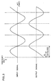
- Fig. 3 is waveform chart that shows an ac signal that is inputted to an phase-control circuit of the coordinate input device and the resulting ac signal outputted from the circuit with a shifted phase.
- Fig. 4 is a flow chart that shows setting and converting processes of display colors in the above-mentioned coordinate input device.
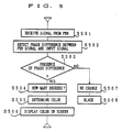
- Fig. 5 is a flow chart that shows setting and converting processes of display colors in the above-mentioned coordinate input device.
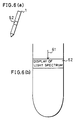
- Figs. 6(a) and 6(b) are schematic drawings that show an arrangement wherein a pen has a scale and a rotation section that serve as a color-setting means in the above-mentioned coordinate input device.
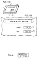
- Figs. 7(a) and 7(b) are explanatory drawings that show an example wherein a bar, displayed on a tablet, functions as a color-setting means in the above-mentioned coordinate input device.
- Fig. 8 is a drawing that shows a color-setting table of the above-mentioned coordinate input device.
- the coordinate input device of the present embodiment is provided with: a pen 1, a tablet (panel) 2, a color liquid crystal display 3, a pen/color conversion circuit 4, a VRAM 5, a tablet controller 6, a display controller 7, a CPU 8, a ROM (a program-recording medium) 9, a RAM 10 and a bus line 11.
- the pen 1 specifies a position on the tablet 2 when it comes into contact therewith, and serves as a pointing means for inputting coordinates of the position.
- the tablet 2 detects a signal outputted from the pen 1, and converts it into coordinate data regarding the position specified by the pen 1.
- the color liquid crystal display 3, placed on the under-surface of the tablet 2, is a display means for displaying an image of the position specified by the pen 1 including its locus.
- the pen/color conversion circuit 4 is a color conversion means including a phase control circuit 13, a phase detector circuit 16 and color conversion circuit 17 (see Fig. 2), which will be described later.
- the pen/color conversion circuit 4 converts a display color into a desired color that has been set and selected by a setting means from limitless kinds of colors, as will be described later.
- the VRAM 5 stores displayed images.
- the tablet controller 6 controls data from the tablet 2, and the display controller 7 controls the display 3 so that an image is displayed on the color display 3 based on the coordinate data.
- the ROM 9 and the RAM 10 store data and processing programs.
- the ROM 9 stores programs for controlling the operation of the apparatus main body.
- the RAM 10 temporarily stores color data.
- the CPU 8 controls the VRAM 5, the tablet controller 6, the display controller 7, the ROM 9, the RAM 10 and other devices based upon the programs stored in the ROM 9.
- the bus line 11 is a line for transferring data.
- the bus line 11 transmits data from the ROM 9, the RAM 10, the tablet controller 6 and the display controller 7 to the CPU 8.
- the devices such as the CPU 8, the ROM 9 and RAM 10, may be provided as media that can be freely installed and removed as external devices.
- the tablet controller 6 Upon carrying out a coordinate input, the tablet controller 6 sends a signal to the pen 1 that is in contact with the tablet 2, and also receives coordinate data regarding the specified position of the pen 1 from the tablet 2.
- the pen/color conversion circuit 4 sends data of a color signal regarding the color thus set and selected to the CPU 8 through the bus line 11, based upon the phase detection of the input signal from the pen 1.
- the CPU 8 stores the data of the color signal regarding the color set and selected from limitless kinds of colors in the RAM 10 in accordance with a command of a corresponding program stored in the ROM 9.
- the tablet 2 outputs the coordinate data in response to the contact of the pen 1, and the coordinate data is inputted to the CPU 8 through the tablet controller 6.
- the CPU 8 sends the coordinate data and the color data stored in the RAM 10 to the display controller 7 in accordance with a command from the ROM 9.
- the display controller 7 converts the coordinate data and color data into color-image data, and stores it in the VRAM 5.
- the color-image data, released from the VRAM 5, is sent to the color display 3 through the display controller 7, and displayed thereon.
- the present coordinate input device is provided with a phase-control circuit 13, a pen-output circuit 14, a Sense Amp circuit 15, a phase-detection circuit (phase-difference detection means) 16 and a color-conversion circuit 17, in order to convert display colors.
- the phase-control circuit 13 serves as a phase-conversion means for shifting the phase of an input ac signal based upon the setting made by the operator.
- the Sense Amp circuit 15 is an amplification circuit for amplifying a minute signal
- the phase-detection circuit 16 is a circuit for detecting the phase difference between an input signal 31 and an output signal 32.
- the color-conversion circuit 17 is a circuit for setting a color from the phase difference detected by the phase-detection circuit 16.
- Fig. 3 is a drawing that shows examples of waveforms of the input signal 31 and output signal 32.
- the axis of abscissa represents time and the axis of ordinate represents voltage.
- one cycle of the waveform is defined as 360 degrees.
- the input signal 31 represents a waveform of an ac signal released from the device main body
- the output signal 32 represents a waveform of an ac signal inputted from the tablet 2.
- the input ac signal 31 is sent to the phase-control circuit 13 and the phase-detection circuit 16 through cables.
- the input signal 31, sent to the phase-control circuit 13, has its phase shifted, for example, by ⁇ 1 based upon the setting made by the operator, and is outputted with the waveform of the output signal 32.
- the signal whose phase has been shifted by ⁇ 1, is transmitted to the tablet 2 through the tip of the pen 1 by the pen-output circuit 14. Upon receipt of the signal, the tablet 2 transmits the received signal as an input signal.
- the input signal, transmitted by the tablet 2, is amplified by the Sense Amp circuit 15 since it is a weak signal.
- the phase-detection circuit 16 detects the phase difference between the resulting amplified signal and the input signal 31 from the device main body, and sends the detected voltage value to the color-conversion circuit 17, and the color-conversion circuit 17 sends a signal representative of a color that is predeterminately set depending on the voltage value to the device main body.
- the value of ⁇ corresponding the shift is desirably set in the range of 0 ⁇ ⁇ ⁇ 360.
- Fig. 4 is a flow chart indicating the color setting and converting processes.
- the operator selects and determines which color to be set (S401), and adjusts the mark of a scale installed on the setting means such as the rotation section 62 of the pen 1 or the bar 71 on the tablet 2 to the color to be set (S402).
- a signal representative of the set color is sent to the phase-control circuit 13, and is used for specifying the phase (S403). Based upon the phase thus specified, the phase of a signal that is to be inputted to the pen 1 is shifted (S404).
- the phase-detection circuit 16 upon receipt of the signal from the pen 1 through the phase-control circuit 13 (S501), the phase-detection circuit 16 detects the phase difference in comparison with the input signal from the device main body (S502), and if the phase-detection circuit 16 recognizes that there is a phase difference (S503), it detects the degree of the phase difference (S504).
- the color-conversion circuit 17 determines the color depending on the phase difference thus detected (S505). Upon receipt of the signal, the display 3 replaces the display color (S506). Here, if there is no phase difference (S507), the color is specified as black (S508).
- Fig. 6 shows a construction wherein the pen 1 has the scale mark 61 and the rotation section 62 as the setting means.
- the rotation section 62 is installed so as to rotate centered on the axis of the pen 1, and the light spectrum, color samples ranging from purple to red, or other samples is displayed on its surface. Further, the scale mark 61, which is provided as a line, an arrow or other marks, indicates the color which has been selected and set.
- Fig. 7 is an explanatory drawing that exemplifies a case in which the bar (color-selection information) 71 displayed on the tablet 2 is used as the setting means.
- the light spectrum, color samples ranging from purple to red, or other samples is displayed on the bar 71. Further, display sections 72 and 73 show, for example, ratios at which purple and red are contained in the color components of a specific display color as numeric values.
- the color components of the display color are displayed in the display sections 71 and 72 as numeric values; therefore, in the case when the display color is reset, it is possible to easily reset it to even a subtle color by merely confirming the displayed numeric values.
- Fig. 8 shows a setting table of colors that are set in the color-conversion circuit 17.
- purple is represented by a numeric value "0”
- red is represented by a numeric value "360”; and between these colors, virtually limitless kinds of colors can be set.
- the color-conversion circuit 17 converts the phase difference between signals sent from the phase-detection circuit 16 to a color based upon the set numeric values.
Landscapes
- Engineering & Computer Science (AREA)
- General Engineering & Computer Science (AREA)
- Theoretical Computer Science (AREA)
- Human Computer Interaction (AREA)
- Physics & Mathematics (AREA)
- General Physics & Mathematics (AREA)
- Position Input By Displaying (AREA)
- Controls And Circuits For Display Device (AREA)
- User Interface Of Digital Computer (AREA)
Applications Claiming Priority (3)
| Application Number | Priority Date | Filing Date | Title |
|---|---|---|---|
| JP244352/96 | 1996-09-17 | ||
| JP24435296 | 1996-09-17 | ||
| JP8244352A JPH1091316A (ja) | 1996-09-17 | 1996-09-17 | 座標入力装置及びそのためのプログラム記録媒体 |
Publications (3)
| Publication Number | Publication Date |
|---|---|
| EP0829800A2 true EP0829800A2 (de) | 1998-03-18 |
| EP0829800A3 EP0829800A3 (de) | 1999-01-20 |
| EP0829800B1 EP0829800B1 (de) | 2003-01-15 |
Family
ID=17117431
Family Applications (1)
| Application Number | Title | Priority Date | Filing Date |
|---|---|---|---|
| EP97115001A Expired - Lifetime EP0829800B1 (de) | 1996-09-17 | 1997-08-29 | Koordinateneingabevorrichtung |
Country Status (4)
| Country | Link |
|---|---|
| US (1) | US6140999A (de) |
| EP (1) | EP0829800B1 (de) |
| JP (1) | JPH1091316A (de) |
| DE (1) | DE69718401T2 (de) |
Cited By (2)
| Publication number | Priority date | Publication date | Assignee | Title |
|---|---|---|---|---|
| WO2013063714A1 (zh) * | 2011-10-31 | 2013-05-10 | Tsao Yung Hsin | 可切换颜色且具颜色标示功能的触控笔 |
| EP2684109A4 (de) * | 2011-03-07 | 2014-09-17 | Creative Tech Ltd | Verfahren, system und elektronische vorrichtung für identifikationen auf assoziationsbasis |
Families Citing this family (5)
| Publication number | Priority date | Publication date | Assignee | Title |
|---|---|---|---|---|
| JP2000284895A (ja) | 1999-03-31 | 2000-10-13 | Hitachi Software Eng Co Ltd | 座標入力ペン並びにそれを用いた電子ボード、座標入力システム及び電子ボードシステム |
| US6377248B1 (en) | 1999-09-30 | 2002-04-23 | Tony S. Partow | High voltage stylus for portable computer |
| US20050129308A1 (en) * | 2003-12-10 | 2005-06-16 | International Business Machines Corporation | Method, apparatus and program storage device for identifying a color of a displayed item using a non-color indicator |
| JP3897018B2 (ja) * | 2003-12-11 | 2007-03-22 | 日本電気株式会社 | ペン型ポインティングデバイス |
| TW200925942A (en) * | 2007-12-10 | 2009-06-16 | Mitac Int Corp | Stylus device with multi-color switching |
Family Cites Families (11)
| Publication number | Priority date | Publication date | Assignee | Title |
|---|---|---|---|---|
| DE3586927T2 (de) * | 1984-04-20 | 1993-06-03 | Hitachi Ltd | Flaches bildschirmanzeigesystem mit integriertem eingabegeraet. |
| JPS621024A (ja) * | 1985-06-26 | 1987-01-07 | Toshiba Corp | 座標入力装置 |
| DE3789922T2 (de) * | 1986-07-23 | 1995-01-05 | Wacom Co Ltd | Koordinateneingabesystem. |
| DE3889182T2 (de) * | 1987-08-24 | 1994-10-13 | Wacom Co Ltd | Koordinateneingabesystem mit einem Eingabeschreibstift. |
| JP3111087B2 (ja) * | 1990-09-06 | 2000-11-20 | シャープ株式会社 | 信号入力装置 |
| JPH04177518A (ja) * | 1990-11-09 | 1992-06-24 | Omron Corp | カラー描画装置 |
| US5420607A (en) * | 1992-09-02 | 1995-05-30 | Miller; Robert F. | Electronic paintbrush and color palette |
| CA2098419A1 (en) * | 1992-09-28 | 1994-03-29 | International Business Machines Corporation | Method and apparatus for interacting with a user interface for a pen-based computing system |
| GB2273778A (en) * | 1992-12-22 | 1994-06-29 | Tds Cad Graphics Limited | Cordless digitizer |
| JPH06266490A (ja) * | 1993-03-12 | 1994-09-22 | Toshiba Corp | 情報入力装置および情報入力における位置認識システム |
| JPH08115154A (ja) * | 1994-10-17 | 1996-05-07 | Tamura Electric Works Ltd | ペン入力装置 |
-
1996
- 1996-09-17 JP JP8244352A patent/JPH1091316A/ja active Pending
-
1997
- 1997-08-29 DE DE69718401T patent/DE69718401T2/de not_active Expired - Lifetime
- 1997-08-29 EP EP97115001A patent/EP0829800B1/de not_active Expired - Lifetime
- 1997-09-03 US US08/922,451 patent/US6140999A/en not_active Expired - Lifetime
Cited By (2)
| Publication number | Priority date | Publication date | Assignee | Title |
|---|---|---|---|---|
| EP2684109A4 (de) * | 2011-03-07 | 2014-09-17 | Creative Tech Ltd | Verfahren, system und elektronische vorrichtung für identifikationen auf assoziationsbasis |
| WO2013063714A1 (zh) * | 2011-10-31 | 2013-05-10 | Tsao Yung Hsin | 可切换颜色且具颜色标示功能的触控笔 |
Also Published As
| Publication number | Publication date |
|---|---|
| JPH1091316A (ja) | 1998-04-10 |
| EP0829800B1 (de) | 2003-01-15 |
| DE69718401T2 (de) | 2003-10-30 |
| DE69718401D1 (de) | 2003-02-20 |
| EP0829800A3 (de) | 1999-01-20 |
| US6140999A (en) | 2000-10-31 |
Similar Documents
| Publication | Publication Date | Title |
|---|---|---|
| JP2682364B2 (ja) | 電子楽器のデータ設定装置 | |
| EP0283995B1 (de) | Berührungsgesteuertes Zoom für Wellenformanzeigen | |
| EP0622723B1 (de) | System und Verfahren zur dynamischen Kennzeichnung von berührungsempfindlichen Knöpfen in einem digitalisierenden Anzeigegerät | |
| JP3996852B2 (ja) | 表示されたスライドの予め選択された部分を強調表示するためのタッチパッドを備えたリモートコントロール | |
| US6538670B1 (en) | Pointing method | |
| US20020080150A1 (en) | Graphical display adjusting system | |
| US5442375A (en) | Method and apparatus for identifying color usage on a monochrome display | |
| US6140999A (en) | Coordinate input device and a program-recording medium for use in such a device | |
| JPH10289212A (ja) | グラフ表示機能を備えた電子式計算機 | |
| EP0623872A1 (de) | Apparat zur Informationsverarbeitung durch Ausführung einer Operation, die gemäss einem Koordinatenwert aus Datenverarbeitungsoperationen ausgewählt worden ist | |
| JPH08115154A (ja) | ペン入力装置 | |
| JPH08140120A (ja) | 色相表示方法および色相表示装置 | |
| GB2285205A (en) | System for contracting bit map image data | |
| JPS63208921A (ja) | スイツチパタ−ン表示装置 | |
| JPH09297858A (ja) | 描画装置 | |
| US5453760A (en) | Position detecting apparatus | |
| JPH10198545A (ja) | 表示制御装置及び表示制御方法 | |
| JP3804065B2 (ja) | 波形測定器 | |
| JPH08272516A (ja) | 情報処理装置 | |
| JPH03265920A (ja) | ポインティング処理方式 | |
| JPS63204431A (ja) | 画像処理装置 | |
| JPH02188787A (ja) | カーソル表示制御装置 | |
| JP2019125403A (ja) | 表示入力装置および表示方法 | |
| JP3186175B2 (ja) | 自動製図装置 | |
| JP2682364C (de) |
Legal Events
| Date | Code | Title | Description |
|---|---|---|---|
| PUAI | Public reference made under article 153(3) epc to a published international application that has entered the european phase |
Free format text: ORIGINAL CODE: 0009012 |
|
| AK | Designated contracting states |
Kind code of ref document: A2 Designated state(s): DE FR GB |
|
| PUAL | Search report despatched |
Free format text: ORIGINAL CODE: 0009013 |
|
| AK | Designated contracting states |
Kind code of ref document: A3 Designated state(s): AT BE CH DE DK ES FI FR GB GR IE IT LI LU MC NL PT SE |
|
| 17P | Request for examination filed |
Effective date: 19990407 |
|
| AKX | Designation fees paid |
Free format text: DE FR GB |
|
| 17Q | First examination report despatched |
Effective date: 20011213 |
|
| GRAG | Despatch of communication of intention to grant |
Free format text: ORIGINAL CODE: EPIDOS AGRA |
|
| GRAG | Despatch of communication of intention to grant |
Free format text: ORIGINAL CODE: EPIDOS AGRA |
|
| GRAH | Despatch of communication of intention to grant a patent |
Free format text: ORIGINAL CODE: EPIDOS IGRA |
|
| GRAH | Despatch of communication of intention to grant a patent |
Free format text: ORIGINAL CODE: EPIDOS IGRA |
|
| GRAA | (expected) grant |
Free format text: ORIGINAL CODE: 0009210 |
|
| AK | Designated contracting states |
Kind code of ref document: B1 Designated state(s): DE FR GB |
|
| REG | Reference to a national code |
Ref country code: GB Ref legal event code: FG4D |
|
| REF | Corresponds to: |
Ref document number: 69718401 Country of ref document: DE Date of ref document: 20030220 Kind code of ref document: P |
|
| ET | Fr: translation filed | ||
| PLBE | No opposition filed within time limit |
Free format text: ORIGINAL CODE: 0009261 |
|
| STAA | Information on the status of an ep patent application or granted ep patent |
Free format text: STATUS: NO OPPOSITION FILED WITHIN TIME LIMIT |
|
| 26N | No opposition filed |
Effective date: 20031016 |
|
| PGFP | Annual fee paid to national office [announced via postgrant information from national office to epo] |
Ref country code: DE Payment date: 20130821 Year of fee payment: 17 |
|
| PGFP | Annual fee paid to national office [announced via postgrant information from national office to epo] |
Ref country code: GB Payment date: 20130828 Year of fee payment: 17 Ref country code: FR Payment date: 20130808 Year of fee payment: 17 |
|
| REG | Reference to a national code |
Ref country code: DE Ref legal event code: R119 Ref document number: 69718401 Country of ref document: DE |
|
| GBPC | Gb: european patent ceased through non-payment of renewal fee |
Effective date: 20140829 |
|
| REG | Reference to a national code |
Ref country code: FR Ref legal event code: ST Effective date: 20150430 |
|
| PG25 | Lapsed in a contracting state [announced via postgrant information from national office to epo] |
Ref country code: GB Free format text: LAPSE BECAUSE OF NON-PAYMENT OF DUE FEES Effective date: 20140829 Ref country code: DE Free format text: LAPSE BECAUSE OF NON-PAYMENT OF DUE FEES Effective date: 20150303 |
|
| PG25 | Lapsed in a contracting state [announced via postgrant information from national office to epo] |
Ref country code: FR Free format text: LAPSE BECAUSE OF NON-PAYMENT OF DUE FEES Effective date: 20140901 |