EP0830106B1 - Tissue loading system for implantable biological devices - Google Patents
Tissue loading system for implantable biological devices Download PDFInfo
- Publication number
- EP0830106B1 EP0830106B1 EP96920211A EP96920211A EP0830106B1 EP 0830106 B1 EP0830106 B1 EP 0830106B1 EP 96920211 A EP96920211 A EP 96920211A EP 96920211 A EP96920211 A EP 96920211A EP 0830106 B1 EP0830106 B1 EP 0830106B1
- Authority
- EP
- European Patent Office
- Prior art keywords
- tissue
- cells
- assembly
- implant
- boundary
- Prior art date
- Legal status (The legal status is an assumption and is not a legal conclusion. Google has not performed a legal analysis and makes no representation as to the accuracy of the status listed.)
- Expired - Lifetime
Links
- 238000011068 loading method Methods 0.000 title claims description 46
- 239000007943 implant Substances 0.000 claims abstract description 117
- 239000000463 material Substances 0.000 claims abstract description 100
- 238000000034 method Methods 0.000 claims abstract description 86
- 239000011159 matrix material Substances 0.000 claims description 43
- 239000012530 fluid Substances 0.000 claims description 31
- 238000007789 sealing Methods 0.000 claims description 25
- 235000015097 nutrients Nutrition 0.000 claims description 24
- 229920002678 cellulose Polymers 0.000 claims description 11
- 239000001913 cellulose Substances 0.000 claims description 11
- 238000004891 communication Methods 0.000 claims description 9
- 239000011734 sodium Substances 0.000 claims description 9
- FHVDTGUDJYJELY-UHFFFAOYSA-N 6-{[2-carboxy-4,5-dihydroxy-6-(phosphanyloxy)oxan-3-yl]oxy}-4,5-dihydroxy-3-phosphanyloxane-2-carboxylic acid Chemical compound O1C(C(O)=O)C(P)C(O)C(O)C1OC1C(C(O)=O)OC(OP)C(O)C1O FHVDTGUDJYJELY-UHFFFAOYSA-N 0.000 claims description 8
- 229940072056 alginate Drugs 0.000 claims description 8
- 235000010443 alginic acid Nutrition 0.000 claims description 8
- 229920000615 alginic acid Polymers 0.000 claims description 8
- 235000010418 carrageenan Nutrition 0.000 claims description 8
- 229920001525 carrageenan Polymers 0.000 claims description 8
- 229940050561 matrix product Drugs 0.000 claims description 8
- 229910052708 sodium Inorganic materials 0.000 claims description 7
- 229920000936 Agarose Polymers 0.000 claims description 6
- LFQSCWFLJHTTHZ-UHFFFAOYSA-N Ethanol Chemical group CCO LFQSCWFLJHTTHZ-UHFFFAOYSA-N 0.000 claims description 6
- DGAQECJNVWCQMB-PUAWFVPOSA-M Ilexoside XXIX Chemical compound C[C@@H]1CC[C@@]2(CC[C@@]3(C(=CC[C@H]4[C@]3(CC[C@@H]5[C@@]4(CC[C@@H](C5(C)C)OS(=O)(=O)[O-])C)C)[C@@H]2[C@]1(C)O)C)C(=O)O[C@H]6[C@@H]([C@H]([C@@H]([C@H](O6)CO)O)O)O.[Na+] DGAQECJNVWCQMB-PUAWFVPOSA-M 0.000 claims description 6
- QAOWNCQODCNURD-UHFFFAOYSA-L Sulfate Chemical compound [O-]S([O-])(=O)=O QAOWNCQODCNURD-UHFFFAOYSA-L 0.000 claims description 6
- 238000000338 in vitro Methods 0.000 claims description 6
- 229920000609 methyl cellulose Polymers 0.000 claims description 6
- 239000001923 methylcellulose Substances 0.000 claims description 6
- 235000010981 methylcellulose Nutrition 0.000 claims description 6
- 229910021653 sulphate ion Inorganic materials 0.000 claims description 6
- GKTNLYAAZKKMTQ-UHFFFAOYSA-N n-[bis(dimethylamino)phosphinimyl]-n-methylmethanamine Chemical compound CN(C)P(=N)(N(C)C)N(C)C GKTNLYAAZKKMTQ-UHFFFAOYSA-N 0.000 claims description 5
- 238000003825 pressing Methods 0.000 claims description 5
- 229920001661 Chitosan Polymers 0.000 claims description 4
- 239000000126 substance Substances 0.000 claims description 4
- 210000004027 cell Anatomy 0.000 description 306
- 210000001519 tissue Anatomy 0.000 description 130
- 210000004379 membrane Anatomy 0.000 description 73
- 239000012528 membrane Substances 0.000 description 73
- 230000035699 permeability Effects 0.000 description 51
- 230000000712 assembly Effects 0.000 description 50
- 238000000429 assembly Methods 0.000 description 50
- 239000011148 porous material Substances 0.000 description 44
- 230000000302 ischemic effect Effects 0.000 description 39
- NOESYZHRGYRDHS-UHFFFAOYSA-N insulin Chemical compound N1C(=O)C(NC(=O)C(CCC(N)=O)NC(=O)C(CCC(O)=O)NC(=O)C(C(C)C)NC(=O)C(NC(=O)CN)C(C)CC)CSSCC(C(NC(CO)C(=O)NC(CC(C)C)C(=O)NC(CC=2C=CC(O)=CC=2)C(=O)NC(CCC(N)=O)C(=O)NC(CC(C)C)C(=O)NC(CCC(O)=O)C(=O)NC(CC(N)=O)C(=O)NC(CC=2C=CC(O)=CC=2)C(=O)NC(CSSCC(NC(=O)C(C(C)C)NC(=O)C(CC(C)C)NC(=O)C(CC=2C=CC(O)=CC=2)NC(=O)C(CC(C)C)NC(=O)C(C)NC(=O)C(CCC(O)=O)NC(=O)C(C(C)C)NC(=O)C(CC(C)C)NC(=O)C(CC=2NC=NC=2)NC(=O)C(CO)NC(=O)CNC2=O)C(=O)NCC(=O)NC(CCC(O)=O)C(=O)NC(CCCNC(N)=N)C(=O)NCC(=O)NC(CC=3C=CC=CC=3)C(=O)NC(CC=3C=CC=CC=3)C(=O)NC(CC=3C=CC(O)=CC=3)C(=O)NC(C(C)O)C(=O)N3C(CCC3)C(=O)NC(CCCCN)C(=O)NC(C)C(O)=O)C(=O)NC(CC(N)=O)C(O)=O)=O)NC(=O)C(C(C)CC)NC(=O)C(CO)NC(=O)C(C(C)O)NC(=O)C1CSSCC2NC(=O)C(CC(C)C)NC(=O)C(NC(=O)C(CCC(N)=O)NC(=O)C(CC(N)=O)NC(=O)C(NC(=O)C(N)CC=1C=CC=CC=1)C(C)C)CC1=CN=CN1 NOESYZHRGYRDHS-UHFFFAOYSA-N 0.000 description 34
- 230000002503 metabolic effect Effects 0.000 description 33
- 230000002792 vascular Effects 0.000 description 30
- 230000001225 therapeutic effect Effects 0.000 description 28
- 230000004083 survival effect Effects 0.000 description 25
- 239000002775 capsule Substances 0.000 description 24
- 238000002513 implantation Methods 0.000 description 23
- YXFVVABEGXRONW-UHFFFAOYSA-N Toluene Chemical compound CC1=CC=CC=C1 YXFVVABEGXRONW-UHFFFAOYSA-N 0.000 description 18
- 102000004877 Insulin Human genes 0.000 description 17
- 108090001061 Insulin Proteins 0.000 description 17
- 229940125396 insulin Drugs 0.000 description 17
- 230000008901 benefit Effects 0.000 description 16
- 206010028980 Neoplasm Diseases 0.000 description 15
- 210000004969 inflammatory cell Anatomy 0.000 description 15
- 239000004568 cement Substances 0.000 description 14
- 230000002491 angiogenic effect Effects 0.000 description 13
- 230000015572 biosynthetic process Effects 0.000 description 13
- 210000002540 macrophage Anatomy 0.000 description 13
- 238000001000 micrograph Methods 0.000 description 13
- 230000008569 process Effects 0.000 description 13
- 208000027418 Wounds and injury Diseases 0.000 description 12
- 230000004888 barrier function Effects 0.000 description 12
- 230000000694 effects Effects 0.000 description 12
- 238000003475 lamination Methods 0.000 description 12
- 239000000203 mixture Substances 0.000 description 12
- 238000012360 testing method Methods 0.000 description 12
- 229920000728 polyester Polymers 0.000 description 11
- 229920001343 polytetrafluoroethylene Polymers 0.000 description 11
- 239000004810 polytetrafluoroethylene Substances 0.000 description 11
- 238000012546 transfer Methods 0.000 description 11
- 241001465754 Metazoa Species 0.000 description 10
- 238000009792 diffusion process Methods 0.000 description 10
- 210000000416 exudates and transudate Anatomy 0.000 description 10
- 210000002950 fibroblast Anatomy 0.000 description 10
- -1 carboxylatophenoxy Chemical group 0.000 description 9
- 206010012601 diabetes mellitus Diseases 0.000 description 9
- 210000004153 islets of langerhan Anatomy 0.000 description 9
- 210000004072 lung Anatomy 0.000 description 9
- 230000035899 viability Effects 0.000 description 9
- 206010029113 Neovascularisation Diseases 0.000 description 8
- XUIMIQQOPSSXEZ-UHFFFAOYSA-N Silicon Chemical compound [Si] XUIMIQQOPSSXEZ-UHFFFAOYSA-N 0.000 description 8
- 210000000577 adipose tissue Anatomy 0.000 description 8
- 229910052710 silicon Inorganic materials 0.000 description 8
- 239000010703 silicon Substances 0.000 description 8
- 239000002699 waste material Substances 0.000 description 8
- 241000699670 Mus sp. Species 0.000 description 7
- 229920002301 cellulose acetate Polymers 0.000 description 7
- 230000006378 damage Effects 0.000 description 7
- 238000002474 experimental method Methods 0.000 description 7
- 230000012010 growth Effects 0.000 description 7
- 230000028993 immune response Effects 0.000 description 7
- 239000003094 microcapsule Substances 0.000 description 7
- 229920001296 polysiloxane Polymers 0.000 description 7
- 230000004044 response Effects 0.000 description 7
- 230000006870 function Effects 0.000 description 6
- 230000002093 peripheral effect Effects 0.000 description 6
- 230000009894 physiological stress Effects 0.000 description 6
- 108091003079 Bovine Serum Albumin Proteins 0.000 description 5
- 239000006144 Dulbecco’s modified Eagle's medium Substances 0.000 description 5
- 229920000544 Gore-Tex Polymers 0.000 description 5
- 239000000853 adhesive Substances 0.000 description 5
- 230000001070 adhesive effect Effects 0.000 description 5
- 239000012091 fetal bovine serum Substances 0.000 description 5
- 239000000835 fiber Substances 0.000 description 5
- 230000002163 immunogen Effects 0.000 description 5
- 238000003756 stirring Methods 0.000 description 5
- 238000007920 subcutaneous administration Methods 0.000 description 5
- 238000001356 surgical procedure Methods 0.000 description 5
- 241000282412 Homo Species 0.000 description 4
- JGSARLDLIJGVTE-MBNYWOFBSA-N Penicillin G Chemical compound N([C@H]1[C@H]2SC([C@@H](N2C1=O)C(O)=O)(C)C)C(=O)CC1=CC=CC=C1 JGSARLDLIJGVTE-MBNYWOFBSA-N 0.000 description 4
- 241000700159 Rattus Species 0.000 description 4
- 239000007853 buffer solution Substances 0.000 description 4
- 239000002131 composite material Substances 0.000 description 4
- 238000012864 cross contamination Methods 0.000 description 4
- 201000010063 epididymitis Diseases 0.000 description 4
- 230000004907 flux Effects 0.000 description 4
- 239000012510 hollow fiber Substances 0.000 description 4
- 238000001727 in vivo Methods 0.000 description 4
- 229920005989 resin Polymers 0.000 description 4
- 239000011347 resin Substances 0.000 description 4
- 125000006850 spacer group Chemical group 0.000 description 4
- UCSJYZPVAKXKNQ-HZYVHMACSA-N streptomycin Chemical compound CN[C@H]1[C@H](O)[C@@H](O)[C@H](CO)O[C@H]1O[C@@H]1[C@](C=O)(O)[C@H](C)O[C@H]1O[C@@H]1[C@@H](NC(N)=N)[C@H](O)[C@@H](NC(N)=N)[C@H](O)[C@H]1O UCSJYZPVAKXKNQ-HZYVHMACSA-N 0.000 description 4
- 210000004881 tumor cell Anatomy 0.000 description 4
- WQZGKKKJIJFFOK-GASJEMHNSA-N Glucose Natural products OC[C@H]1OC(O)[C@H](O)[C@@H](O)[C@@H]1O WQZGKKKJIJFFOK-GASJEMHNSA-N 0.000 description 3
- 239000004743 Polypropylene Substances 0.000 description 3
- RTAQQCXQSZGOHL-UHFFFAOYSA-N Titanium Chemical compound [Ti] RTAQQCXQSZGOHL-UHFFFAOYSA-N 0.000 description 3
- 150000001875 compounds Chemical class 0.000 description 3
- 238000005516 engineering process Methods 0.000 description 3
- 150000002148 esters Chemical class 0.000 description 3
- 238000011049 filling Methods 0.000 description 3
- 239000000499 gel Substances 0.000 description 3
- 239000008103 glucose Substances 0.000 description 3
- 239000002874 hemostatic agent Substances 0.000 description 3
- 229920001155 polypropylene Polymers 0.000 description 3
- 230000002285 radioactive effect Effects 0.000 description 3
- 210000004872 soft tissue Anatomy 0.000 description 3
- 239000000243 solution Substances 0.000 description 3
- OYPRJOBELJOOCE-UHFFFAOYSA-N Calcium Chemical compound [Ca] OYPRJOBELJOOCE-UHFFFAOYSA-N 0.000 description 2
- 239000004593 Epoxy Substances 0.000 description 2
- 208000005422 Foreign-Body reaction Diseases 0.000 description 2
- SXRSQZLOMIGNAQ-UHFFFAOYSA-N Glutaraldehyde Chemical compound O=CCCCC=O SXRSQZLOMIGNAQ-UHFFFAOYSA-N 0.000 description 2
- WZUVPPKBWHMQCE-UHFFFAOYSA-N Haematoxylin Chemical compound C12=CC(O)=C(O)C=C2CC2(O)C1C1=CC=C(O)C(O)=C1OC2 WZUVPPKBWHMQCE-UHFFFAOYSA-N 0.000 description 2
- 239000012981 Hank's balanced salt solution Substances 0.000 description 2
- ZDXPYRJPNDTMRX-VKHMYHEASA-N L-glutamine Chemical compound OC(=O)[C@@H](N)CCC(N)=O ZDXPYRJPNDTMRX-VKHMYHEASA-N 0.000 description 2
- 229930182816 L-glutamine Natural products 0.000 description 2
- DFPAKSUCGFBDDF-UHFFFAOYSA-N Nicotinamide Chemical compound NC(=O)C1=CC=CN=C1 DFPAKSUCGFBDDF-UHFFFAOYSA-N 0.000 description 2
- KDLHZDBZIXYQEI-UHFFFAOYSA-N Palladium Chemical compound [Pd] KDLHZDBZIXYQEI-UHFFFAOYSA-N 0.000 description 2
- 239000004698 Polyethylene Substances 0.000 description 2
- 102000004142 Trypsin Human genes 0.000 description 2
- 108090000631 Trypsin Proteins 0.000 description 2
- 238000004458 analytical method Methods 0.000 description 2
- 239000000872 buffer Substances 0.000 description 2
- 239000011575 calcium Substances 0.000 description 2
- 229910052791 calcium Inorganic materials 0.000 description 2
- 239000003054 catalyst Substances 0.000 description 2
- 230000003833 cell viability Effects 0.000 description 2
- 230000008859 change Effects 0.000 description 2
- 238000010276 construction Methods 0.000 description 2
- 230000002596 correlated effect Effects 0.000 description 2
- 238000005520 cutting process Methods 0.000 description 2
- 238000000151 deposition Methods 0.000 description 2
- 230000003292 diminished effect Effects 0.000 description 2
- 201000010099 disease Diseases 0.000 description 2
- 208000037265 diseases, disorders, signs and symptoms Diseases 0.000 description 2
- 239000003814 drug Substances 0.000 description 2
- 238000005538 encapsulation Methods 0.000 description 2
- 210000002889 endothelial cell Anatomy 0.000 description 2
- 229920000295 expanded polytetrafluoroethylene Polymers 0.000 description 2
- 238000002594 fluoroscopy Methods 0.000 description 2
- 239000001963 growth medium Substances 0.000 description 2
- 239000000017 hydrogel Substances 0.000 description 2
- 238000002347 injection Methods 0.000 description 2
- 239000007924 injection Substances 0.000 description 2
- 208000014674 injury Diseases 0.000 description 2
- 238000002955 isolation Methods 0.000 description 2
- 238000011694 lewis rat Methods 0.000 description 2
- 230000007246 mechanism Effects 0.000 description 2
- 230000004060 metabolic process Effects 0.000 description 2
- 229940056360 penicillin g Drugs 0.000 description 2
- 210000003200 peritoneal cavity Anatomy 0.000 description 2
- 229920000573 polyethylene Polymers 0.000 description 2
- 229920000642 polymer Polymers 0.000 description 2
- 239000013464 silicone adhesive Substances 0.000 description 2
- 229960005322 streptomycin Drugs 0.000 description 2
- 239000000758 substrate Substances 0.000 description 2
- 230000002459 sustained effect Effects 0.000 description 2
- 229940124597 therapeutic agent Drugs 0.000 description 2
- 229910052719 titanium Inorganic materials 0.000 description 2
- 239000010936 titanium Substances 0.000 description 2
- 230000032258 transport Effects 0.000 description 2
- 239000012588 trypsin Substances 0.000 description 2
- 229920002554 vinyl polymer Polymers 0.000 description 2
- 238000003466 welding Methods 0.000 description 2
- DIIIISSCIXVANO-UHFFFAOYSA-N 1,2-Dimethylhydrazine Chemical compound CNNC DIIIISSCIXVANO-UHFFFAOYSA-N 0.000 description 1
- JKMHFZQWWAIEOD-UHFFFAOYSA-N 2-[4-(2-hydroxyethyl)piperazin-1-yl]ethanesulfonic acid Chemical compound OCC[NH+]1CCN(CCS([O-])(=O)=O)CC1 JKMHFZQWWAIEOD-UHFFFAOYSA-N 0.000 description 1
- ZCYVEMRRCGMTRW-UHFFFAOYSA-N 7553-56-2 Chemical compound [I] ZCYVEMRRCGMTRW-UHFFFAOYSA-N 0.000 description 1
- 229920001817 Agar Polymers 0.000 description 1
- 102000008186 Collagen Human genes 0.000 description 1
- 108010035532 Collagen Proteins 0.000 description 1
- 208000027219 Deficiency disease Diseases 0.000 description 1
- 206010013082 Discomfort Diseases 0.000 description 1
- 208000001382 Experimental Melanoma Diseases 0.000 description 1
- 239000007995 HEPES buffer Substances 0.000 description 1
- 239000000020 Nitrocellulose Substances 0.000 description 1
- 239000004677 Nylon Substances 0.000 description 1
- LCTONWCANYUPML-UHFFFAOYSA-M Pyruvate Chemical compound CC(=O)C([O-])=O LCTONWCANYUPML-UHFFFAOYSA-M 0.000 description 1
- BQCADISMDOOEFD-UHFFFAOYSA-N Silver Chemical compound [Ag] BQCADISMDOOEFD-UHFFFAOYSA-N 0.000 description 1
- FAPWRFPIFSIZLT-UHFFFAOYSA-M Sodium chloride Chemical compound [Na+].[Cl-] FAPWRFPIFSIZLT-UHFFFAOYSA-M 0.000 description 1
- ZSJLQEPLLKMAKR-UHFFFAOYSA-N Streptozotocin Natural products O=NN(C)C(=O)NC1C(O)OC(CO)C(O)C1O ZSJLQEPLLKMAKR-UHFFFAOYSA-N 0.000 description 1
- FJWGYAHXMCUOOM-QHOUIDNNSA-N [(2s,3r,4s,5r,6r)-2-[(2r,3r,4s,5r,6s)-4,5-dinitrooxy-2-(nitrooxymethyl)-6-[(2r,3r,4s,5r,6s)-4,5,6-trinitrooxy-2-(nitrooxymethyl)oxan-3-yl]oxyoxan-3-yl]oxy-3,5-dinitrooxy-6-(nitrooxymethyl)oxan-4-yl] nitrate Chemical compound O([C@@H]1O[C@@H]([C@H]([C@H](O[N+]([O-])=O)[C@H]1O[N+]([O-])=O)O[C@H]1[C@@H]([C@@H](O[N+]([O-])=O)[C@H](O[N+]([O-])=O)[C@@H](CO[N+]([O-])=O)O1)O[N+]([O-])=O)CO[N+](=O)[O-])[C@@H]1[C@@H](CO[N+]([O-])=O)O[C@@H](O[N+]([O-])=O)[C@H](O[N+]([O-])=O)[C@H]1O[N+]([O-])=O FJWGYAHXMCUOOM-QHOUIDNNSA-N 0.000 description 1
- 210000000683 abdominal cavity Anatomy 0.000 description 1
- 230000003187 abdominal effect Effects 0.000 description 1
- 210000003815 abdominal wall Anatomy 0.000 description 1
- 230000001464 adherent effect Effects 0.000 description 1
- 230000002411 adverse Effects 0.000 description 1
- 239000008272 agar Substances 0.000 description 1
- 230000004075 alteration Effects 0.000 description 1
- XAGFODPZIPBFFR-UHFFFAOYSA-N aluminium Chemical compound [Al] XAGFODPZIPBFFR-UHFFFAOYSA-N 0.000 description 1
- 229910052782 aluminium Inorganic materials 0.000 description 1
- 239000002870 angiogenesis inducing agent Substances 0.000 description 1
- 238000003556 assay Methods 0.000 description 1
- 230000001580 bacterial effect Effects 0.000 description 1
- 239000011324 bead Substances 0.000 description 1
- 230000009286 beneficial effect Effects 0.000 description 1
- 230000007321 biological mechanism Effects 0.000 description 1
- 230000031018 biological processes and functions Effects 0.000 description 1
- 230000033228 biological regulation Effects 0.000 description 1
- 230000000903 blocking effect Effects 0.000 description 1
- 210000004369 blood Anatomy 0.000 description 1
- 239000008280 blood Substances 0.000 description 1
- 239000000679 carrageenan Substances 0.000 description 1
- 229940113118 carrageenan Drugs 0.000 description 1
- 210000000845 cartilage Anatomy 0.000 description 1
- 230000030833 cell death Effects 0.000 description 1
- 239000006285 cell suspension Substances 0.000 description 1
- 230000019522 cellular metabolic process Effects 0.000 description 1
- 238000005119 centrifugation Methods 0.000 description 1
- 239000000919 ceramic Substances 0.000 description 1
- 210000004081 cilia Anatomy 0.000 description 1
- 229920001436 collagen Polymers 0.000 description 1
- 201000010897 colon adenocarcinoma Diseases 0.000 description 1
- 208000029742 colonic neoplasm Diseases 0.000 description 1
- 230000000295 complement effect Effects 0.000 description 1
- 238000004590 computer program Methods 0.000 description 1
- 210000002808 connective tissue Anatomy 0.000 description 1
- 238000011109 contamination Methods 0.000 description 1
- 238000007796 conventional method Methods 0.000 description 1
- 238000001816 cooling Methods 0.000 description 1
- 238000012937 correction Methods 0.000 description 1
- 238000002788 crimping Methods 0.000 description 1
- 239000005331 crown glasses (windows) Substances 0.000 description 1
- 210000004748 cultured cell Anatomy 0.000 description 1
- 238000012258 culturing Methods 0.000 description 1
- 108010038204 cytoplasmic linker protein 190 Proteins 0.000 description 1
- 230000008021 deposition Effects 0.000 description 1
- 238000009795 derivation Methods 0.000 description 1
- 238000001514 detection method Methods 0.000 description 1
- 238000011161 development Methods 0.000 description 1
- 230000018109 developmental process Effects 0.000 description 1
- LOKCTEFSRHRXRJ-UHFFFAOYSA-I dipotassium trisodium dihydrogen phosphate hydrogen phosphate dichloride Chemical compound P(=O)(O)(O)[O-].[K+].P(=O)(O)([O-])[O-].[Na+].[Na+].[Cl-].[K+].[Cl-].[Na+] LOKCTEFSRHRXRJ-UHFFFAOYSA-I 0.000 description 1
- 238000009826 distribution Methods 0.000 description 1
- 229920001971 elastomer Polymers 0.000 description 1
- 239000000806 elastomer Substances 0.000 description 1
- 238000001493 electron microscopy Methods 0.000 description 1
- 210000002257 embryonic structure Anatomy 0.000 description 1
- 238000002674 endoscopic surgery Methods 0.000 description 1
- YQGOJNYOYNNSMM-UHFFFAOYSA-N eosin Chemical compound [Na+].OC(=O)C1=CC=CC=C1C1=C2C=C(Br)C(=O)C(Br)=C2OC2=C(Br)C(O)=C(Br)C=C21 YQGOJNYOYNNSMM-UHFFFAOYSA-N 0.000 description 1
- 210000002615 epidermis Anatomy 0.000 description 1
- 125000003700 epoxy group Chemical group 0.000 description 1
- 239000000284 extract Substances 0.000 description 1
- 230000003176 fibrotic effect Effects 0.000 description 1
- 238000007667 floating Methods 0.000 description 1
- 235000013373 food additive Nutrition 0.000 description 1
- 239000002778 food additive Substances 0.000 description 1
- 239000012737 fresh medium Substances 0.000 description 1
- 238000002695 general anesthesia Methods 0.000 description 1
- 230000002068 genetic effect Effects 0.000 description 1
- 210000004408 hybridoma Anatomy 0.000 description 1
- 230000002209 hydrophobic effect Effects 0.000 description 1
- 238000003384 imaging method Methods 0.000 description 1
- 230000008076 immune mechanism Effects 0.000 description 1
- 230000006872 improvement Effects 0.000 description 1
- 238000000099 in vitro assay Methods 0.000 description 1
- 230000002757 inflammatory effect Effects 0.000 description 1
- 230000003914 insulin secretion Effects 0.000 description 1
- 230000003993 interaction Effects 0.000 description 1
- 230000009545 invasion Effects 0.000 description 1
- 238000012977 invasive surgical procedure Methods 0.000 description 1
- 229910052740 iodine Inorganic materials 0.000 description 1
- 239000011630 iodine Substances 0.000 description 1
- 150000002500 ions Chemical class 0.000 description 1
- 239000007788 liquid Substances 0.000 description 1
- 239000011344 liquid material Substances 0.000 description 1
- 230000004807 localization Effects 0.000 description 1
- 230000033001 locomotion Effects 0.000 description 1
- 210000005075 mammary gland Anatomy 0.000 description 1
- 238000004519 manufacturing process Methods 0.000 description 1
- 239000002609 medium Substances 0.000 description 1
- 239000000155 melt Substances 0.000 description 1
- 239000007769 metal material Substances 0.000 description 1
- 230000001394 metastastic effect Effects 0.000 description 1
- 206010061289 metastatic neoplasm Diseases 0.000 description 1
- 239000012982 microporous membrane Substances 0.000 description 1
- 238000000386 microscopy Methods 0.000 description 1
- 210000004925 microvascular endothelial cell Anatomy 0.000 description 1
- 238000000465 moulding Methods 0.000 description 1
- 229960003966 nicotinamide Drugs 0.000 description 1
- 235000005152 nicotinamide Nutrition 0.000 description 1
- 239000011570 nicotinamide Substances 0.000 description 1
- 229920001220 nitrocellulos Polymers 0.000 description 1
- 235000016709 nutrition Nutrition 0.000 description 1
- 230000035764 nutrition Effects 0.000 description 1
- 229920001778 nylon Polymers 0.000 description 1
- 210000000056 organ Anatomy 0.000 description 1
- 239000003973 paint Substances 0.000 description 1
- 229910052763 palladium Inorganic materials 0.000 description 1
- 238000002559 palpation Methods 0.000 description 1
- 210000000496 pancreas Anatomy 0.000 description 1
- 210000000277 pancreatic duct Anatomy 0.000 description 1
- 230000035515 penetration Effects 0.000 description 1
- 230000002085 persistent effect Effects 0.000 description 1
- 239000002953 phosphate buffered saline Substances 0.000 description 1
- 230000000704 physical effect Effects 0.000 description 1
- 229920002492 poly(sulfone) Polymers 0.000 description 1
- 229920002239 polyacrylonitrile Polymers 0.000 description 1
- 229920000515 polycarbonate Polymers 0.000 description 1
- 239000004417 polycarbonate Substances 0.000 description 1
- 229920000647 polyepoxide Polymers 0.000 description 1
- 229920005597 polymer membrane Polymers 0.000 description 1
- 229920002635 polyurethane Polymers 0.000 description 1
- 239000004814 polyurethane Substances 0.000 description 1
- 229920000131 polyvinylidene Polymers 0.000 description 1
- 235000003784 poor nutrition Nutrition 0.000 description 1
- 238000001556 precipitation Methods 0.000 description 1
- 238000002360 preparation method Methods 0.000 description 1
- 230000035755 proliferation Effects 0.000 description 1
- 230000001737 promoting effect Effects 0.000 description 1
- 229920005604 random copolymer Polymers 0.000 description 1
- 230000008929 regeneration Effects 0.000 description 1
- 238000011069 regeneration method Methods 0.000 description 1
- 230000002441 reversible effect Effects 0.000 description 1
- 230000003248 secreting effect Effects 0.000 description 1
- 230000028327 secretion Effects 0.000 description 1
- 210000002966 serum Anatomy 0.000 description 1
- 229910052709 silver Inorganic materials 0.000 description 1
- 239000004332 silver Substances 0.000 description 1
- 210000003491 skin Anatomy 0.000 description 1
- 210000001626 skin fibroblast Anatomy 0.000 description 1
- 210000000329 smooth muscle myocyte Anatomy 0.000 description 1
- 239000011780 sodium chloride Substances 0.000 description 1
- 239000007787 solid Substances 0.000 description 1
- 238000007711 solidification Methods 0.000 description 1
- 230000008023 solidification Effects 0.000 description 1
- 239000002904 solvent Substances 0.000 description 1
- 238000001179 sorption measurement Methods 0.000 description 1
- 241000894007 species Species 0.000 description 1
- 230000004936 stimulating effect Effects 0.000 description 1
- 230000000638 stimulation Effects 0.000 description 1
- ZSJLQEPLLKMAKR-GKHCUFPYSA-N streptozocin Chemical compound O=NN(C)C(=O)N[C@H]1[C@@H](O)O[C@H](CO)[C@@H](O)[C@@H]1O ZSJLQEPLLKMAKR-GKHCUFPYSA-N 0.000 description 1
- 229960001052 streptozocin Drugs 0.000 description 1
- 230000035882 stress Effects 0.000 description 1
- 238000010254 subcutaneous injection Methods 0.000 description 1
- 239000007929 subcutaneous injection Substances 0.000 description 1
- 238000011477 surgical intervention Methods 0.000 description 1
- 239000000725 suspension Substances 0.000 description 1
- 230000004797 therapeutic response Effects 0.000 description 1
- 230000008467 tissue growth Effects 0.000 description 1
- 238000002054 transplantation Methods 0.000 description 1
- 210000005239 tubule Anatomy 0.000 description 1
- 210000005166 vasculature Anatomy 0.000 description 1
- 238000012795 verification Methods 0.000 description 1
- 230000000007 visual effect Effects 0.000 description 1
- 238000011179 visual inspection Methods 0.000 description 1
- 230000003442 weekly effect Effects 0.000 description 1
- 238000009736 wetting Methods 0.000 description 1
- UHVMMEOXYDMDKI-JKYCWFKZSA-L zinc;1-(5-cyanopyridin-2-yl)-3-[(1s,2s)-2-(6-fluoro-2-hydroxy-3-propanoylphenyl)cyclopropyl]urea;diacetate Chemical compound [Zn+2].CC([O-])=O.CC([O-])=O.CCC(=O)C1=CC=C(F)C([C@H]2[C@H](C2)NC(=O)NC=2N=CC(=CC=2)C#N)=C1O UHVMMEOXYDMDKI-JKYCWFKZSA-L 0.000 description 1
- DGVVWUTYPXICAM-UHFFFAOYSA-N β‐Mercaptoethanol Chemical compound OCCS DGVVWUTYPXICAM-UHFFFAOYSA-N 0.000 description 1
Images


Classifications
-
- A—HUMAN NECESSITIES
- A61—MEDICAL OR VETERINARY SCIENCE; HYGIENE
- A61K—PREPARATIONS FOR MEDICAL, DENTAL OR TOILETRY PURPOSES
- A61K9/00—Medicinal preparations characterised by special physical form
- A61K9/0012—Galenical forms characterised by the site of application
- A61K9/0019—Injectable compositions; Intramuscular, intravenous, arterial, subcutaneous administration; Compositions to be administered through the skin in an invasive manner
- A61K9/0024—Solid, semi-solid or solidifying implants, which are implanted or injected in body tissue
-
- A—HUMAN NECESSITIES
- A61—MEDICAL OR VETERINARY SCIENCE; HYGIENE
- A61F—FILTERS IMPLANTABLE INTO BLOOD VESSELS; PROSTHESES; DEVICES PROVIDING PATENCY TO, OR PREVENTING COLLAPSING OF, TUBULAR STRUCTURES OF THE BODY, e.g. STENTS; ORTHOPAEDIC, NURSING OR CONTRACEPTIVE DEVICES; FOMENTATION; TREATMENT OR PROTECTION OF EYES OR EARS; BANDAGES, DRESSINGS OR ABSORBENT PADS; FIRST-AID KITS
- A61F2/00—Filters implantable into blood vessels; Prostheses, i.e. artificial substitutes or replacements for parts of the body; Appliances for connecting them with the body; Devices providing patency to, or preventing collapsing of, tubular structures of the body, e.g. stents
- A61F2/02—Prostheses implantable into the body
- A61F2/022—Artificial gland structures using bioreactors
-
- A—HUMAN NECESSITIES
- A61—MEDICAL OR VETERINARY SCIENCE; HYGIENE
- A61L—METHODS OR APPARATUS FOR STERILISING MATERIALS OR OBJECTS IN GENERAL; DISINFECTION, STERILISATION OR DEODORISATION OF AIR; CHEMICAL ASPECTS OF BANDAGES, DRESSINGS, ABSORBENT PADS OR SURGICAL ARTICLES; MATERIALS FOR BANDAGES, DRESSINGS, ABSORBENT PADS OR SURGICAL ARTICLES
- A61L27/00—Materials for grafts or prostheses or for coating grafts or prostheses
- A61L27/36—Materials for grafts or prostheses or for coating grafts or prostheses containing ingredients of undetermined constitution or reaction products thereof, e.g. transplant tissue, natural bone, extracellular matrix
- A61L27/38—Materials for grafts or prostheses or for coating grafts or prostheses containing ingredients of undetermined constitution or reaction products thereof, e.g. transplant tissue, natural bone, extracellular matrix containing added animal cells
Definitions
- the inventions relate to systems and methods for in vitro adding tissue to an implant assembly.
- the implanted cells will generate biological products that the host, because of disease or injury, cannot produce for itself.
- the implant assembly can contain pancreatic cells (clusters of which are called "islets”), which generate insulin that a diabetic host lacks.
- pancreatic cells implanted for the treatment of diabetes usually die or become dysfunctional within a few days or weeks after implantation.
- the region of the host tissue next to the implant assembly can be characterized as ischemic.
- "Ischemic” means that there is not a sufficient flow of blood in the tissue region closely surrounding the implant assembly. Usually, this ischemic condition exists during the first two weeks of implantation. Most implanted cells fail to live through this period.
- a foreign body capsule forms around the implanted cells.
- the capsule consists of flattened macrophages, foreign body giant cells, and fibroblasts.
- Conventional hypotheses blame the foreign body capsule for causing implanted cells to die or become dysfunctional during the ischemic period.
- the inventors have previously discovered that the cells do not die because of the intervention of the foreign body capsule. Instead, the cells die because conventional implant assemblies and methodologies themselves lack the innate capacity to support the implanted cells' ongoing life processes during the critical ischemic period, when the host's vascular structures are not nearby. Because of this, the implanted cells perish before the host can grow new vascular structures close enough to sustain them.
- an implant assembly that housed cells within hollow fibers was recently used by CytoTherapeutics to successfully treat diabetes in rats.
- the assembly consisted of 7 fibers, each being 2 cm long and 0.073 cm in diameter.
- the pancreatic cells were present within the fibers at a density of about 25,000 cells per cm 3 .
- it would have to contain at least about 250,000 pancreatic islets (each islet contains about 1000 cells). This means that, to hold enough pancreatic cells to treat human diabetes, the assembly would have to be about 117 ft. (139.9 m). This makes the assembly unusable for clinical use in humans.
- microcapsules tiny hydrogel vessels, called microcapsules. These tiny vessels cannot be implanted within the host's soft tissues, because they lack the physical strength to withstand the physiological stresses normally encountered close to the host tissue. Instead, the microcapsules are suspended in a free floating state within a solution that is infused into the host's peritoneal cavity.
- microcapsules have only limited clinical application. Not all persons can tolerate their injection free of danger or discomfort. Microcapsules are non-adhesive, and they do not stick to organs. Instead, they settle in large masses at the bottom of the peritoneal cavity. And, if implanted directly within the host's tissue, the microcapsules will rupture, and the contained cells would perish. For these reasons, microcapsules fail to provide a widely usable clinical solution to the problems surrounding the therapeutic implantation of cells.
- a large volume matrix as compared to the cells to be implanted, is provided that is mixed with the cells to create a matrix/tissue product.
- the matrix/tissue product by mass, includes matrix at a level that is 10 to 20 times the volume of the cells to be encapsulated.
- a product is provided that includes tissue that is encapsulated by a matrix, however, the tissue only comprises 5 to 10 percent of the volume of the tissue/matrix product; the remaining portion of the product comprises the matrix
- tissue does not provide sufficient tissue for certain applications. This is due to the limited volume of tissue in the tissue/matrix product.
- ported devices i.e., assemblies that include a tube in communication with the interior of the device.
- ported devices i.e., assemblies that include a tube in communication with the interior of the device.
- WO 95/18583 describes ported tissue implant systems and methods for using same.
- WO 93/21902 describes a biocompatible, therapeutic, implantable device and methods of introducing tissue to the device through an access opening.
- the present invention provides a tissue loading system for transferring biological tissue to a device or lumen and methods for creating barriers between the host and implanted tissue.
- the present invention provides an in vitro method of adding tissue to an implant assembly comprising the step of adding a tissue to an implant assembly through an access opening thereof; adding a play creating material to the assembly so/as to seal the opening; and including the step of loading the tissue product and plug creating material in a reservoir, wherein the plug creating material is located at a back end of the reservoir, and applying pressure to the back end of the reservoir to cause the tissue to enter the implant assembly.
- an in vitro method for adding to an implant assembly.
- a fluid is added to the assembly before the tissue.
- the reservoir is in fluid communication with a cannula.
- the reservoir is in fluid communication with a catheter.
- a tissue loading system for adding tissue to an implant assembly comprises a device that includes an interior having therein a tissue product, and a plug creating material located at a back end of the interior in juxtaposition to the tissue product.
- This embodiment provides a method for sealing an implant assembly device that comprises the step of after loading tissue in the implant device through an access opening thereof, adding to the implant device the plug creating material that seals the access opening.
- the method includes the addition of a matrix that is chosen from the group consisting of: alginate; agarose; poly[bis(carboxylatophenoxy(phosphazene); sodium cellulose sulphate; methyl cellulose; chitosan; and carrageenans.
- An advantage of the present invention is that it provides an improved method for transferring biological tissue to a device or lumen and creating barriers between the host and implanted tissue.
- a further advantage of the present invention is that it provides a system in which the device and lumen voids are filled during and following cell transfer.
- an advantage of the present invention is that it minimizes the risk of tissue cross contamination within the host.
- Another advantage of the present invention is that it simplifies tissue loading by matching transfer system to device or lumen.
- an advantage of the present invention is that it provides a "plug" that can be used during transfer to minimize handling and expedite device or lumen closure.
- an advantage of the present invention is that it provides a system technology transfer that can be used in endoscopic surgery methods.
- an advantage of the present invention is that it provides a system that is compatible with prevascularization ported immuno-isolation and other in vivo devices.
- Figs. 1 to 4 show an implant assembly 10.
- the assembly 10 can carry preselected types of living cells 12 for implanting within the soft tissue of a host.
- the implanted cells 12 generate biological products that the host, because of disease or injury, cannot produce for itself.
- the implant assembly 10 can carry clusters of pancreatic cells (called “islets”), which generate insulin for release into and use by a diabetic host.
- islets pancreatic cells
- the assembly 10 forms a porous, life sustaining boundary between the implanted cells 12 and the host.
- the porous boundary isolates the implanted cells 12 from attack and destruction by certain biological mechanisms of the host.
- the porous boundary associates with the host's biological system closely enough to transfer nutrients and wastes in support of the biological processes of the implanted cells 12.
- the porous boundary also transfers the therapeutic products generated by the implanted cells 12 to the host.
- the assembly 10 includes a hoop-like housing 11.
- the housing 11 includes a first hoop element 14 and a second hoop element 16 that nests within the first hoop element 14.
- the assembly 10 also forms a cell chamber 18 within the hoop-like housing 11.
- the first hoop element 14 has an upstanding cylindrical side wall 20 that peripherally defines an open area. First and second central openings 22 and 24 lead into the open area. The first central opening 22 is smaller than the second central opening 24. This forms an interior step or ledge 26 next to the first opening 22.
- the second hoop element 16 also has a central opening 28.
- the second hoop element 16 has an outer diameter that is slightly greater than the inner diameter of the open area of the first hoop element 14.
- the peripheral edge of the second central opening 16 contains a slight chamfer 30 to receive the second hoop element 16.
- the second hoop element 16 nests snugly in an interference press fit within the open area of the first hoop element 14 (see Fig. 2).
- the first hoop element 14 and the second hoop element 16 are made of a durable biocompatible ceramic or metallic material, like titanium. Like titanium, the selected material should also preferably by subject to detection within the host tissue by fluoroscopy, x-ray, and the like.
- the specific dimensions of the hoop-like housing 11 may vary according to its intended use and the volume of cells 12 it contains.
- the side wall of the first hoop element 14 is about .055 inch (0.14 cm) in height and has an outer diameter of about .375 inch (0.95 cm).
- the open area has an inner diameter of about .325 inch (0.82 cm) where it joins the inner edge of the chamber 30 of the second central opening 24.
- the second central opening 24 has an inner diameter of about .326 inch (0.83 cm) around the outer edge of the chamfer 30.
- the first central opening 14 has an inner diameter of about .275 inch (0.70 cm) and a depth of about .015 inch (0.04 cm), where it joints the interior ledge 26.
- the associated second hoop element 16 has a height of about .025 inch (0.06 cm); an outer diameter of about .326 inch (0.83 cm); and an inner diameter (for its central opening 28) of about .250 inch (0.63 cm).
- the range of interference necessary to snugly joint the second hoop element 16 within the first hoop element 14 will of course depend upon the nature of the materials selected.
- the chamber includes a first porous wall element 32, a second porous wall element 34, and a sealing gasket or ring 36 that is sandwiched between them.
- the sealing ring 36 is made of a mesh polyester material.
- the wall elements 32 and 34 and sealing ring 36 are sized to fit snugly within the confines of the hoop-like housing 11. And, as will be described in greater detail later, at least one (and preferably both) porous wall elements 32 and 34 have certain physical characteristics selected to protect and sustain the viability of the cells 12 within the host.
- the ring 36 has a central open region 38.
- the open ring region 38 together with the overlying first and second porous wall elements 32 and 34, create the chamber 18 to hold the implanted cells 12 (see Fig. 4).
- the practitioner lays one wall element 32 onto the ledge 26 formed in the first hoop element 14. The practitioner then lays the sealing ring 36 upon the wall element 32. Next, the practitioner inserts the desired amount of cells 12 to be implanted into the open region 38 of the ring 36. The amount of implanted cells 12 is sufficient to induce the expected therapeutic response in the host.
- the practitioner next lays the other wall element 34 over the first wall element 32, sealing ring 36, and inserted cells 12.
- one wall element 32 rests against the interior ledge 26 and is there exposed through the first central opening 22.
- the other wall element 34 rests against the second hoop element 16 and is there exposed through its central opening 28.
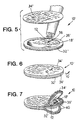
- Figs. 5 to 10 show another implant assembly 10'.
- the assembly 10' includes a cell chamber 18' formed by first and second porous wall elements 32' and 34' and an intermediate sealing ring 36'.
- the assembly 10' does not rely upon the hoop-like housing 11 to hold and seal the chamber 18'. Instead, a preformed peripheral weld 40 bonds and seals the edges of the porous wall elements 32' and 34' to the interior ring 36'.
- the practitioner lays the sealing ring 36' upon one wall element 32' and inserts the desired amount of cells 12 to be implanted into the open region 38' of the ring 36' (see Fig. 5).
- the practitioner overlays the other wall element 34' (as Fig. 6 shows).
- the practitioner then forms the weld 40 to seal the peripheral edges of the first and second wall elements 32' and 34' to the ring 36' (as Fig. 8 shows).
- the weld compresses the peripheral edge of the assembly 10' together, as Fig. 9 shows.
- the practitioner selects a sealing technique that does not damage the cells 12 within the chamber 18'. For example, the inventors find that sonic welding can be used without damage to the inserted tissue cells.
- the practitioner uses a Branson sonic welder.
- the welder is operated at 40 Khz, with 941AES actuator, 947m power supply, and 91C power controller.
- the horn amplitude is about 1.4 mils and is operated at a hold time of about 0.3 seconds; a weld time of about .20 seconds; a pressure of about 50 PSI (3.4x10 5 Pascal) ; a trigger force of about 20 pounds (9.07 kg; and a down speed of about 1.25 (machine setting).
- the integral assembly 10' formed in this manner can be implanted directly within host tissue, without use of an exterior housing.
- the assembly 10' includes an attached clip 42 made of a material that can be detected within the host tissue by fluoroscopy, x-ray, and the like. In this way, the practitioner can easily locate the assembly 10' within the host, if required.
- the specific dimensions of the assembly 10' may vary according to its intended use. And, like the first described embodiment, at least one (and preferably both) porous wall elements 32' and 34' have certain physical characteristics selected to protect and sustain the viability of the cells within the host.
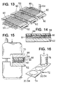
- the practitioner surgically implants it in the soft tissue 44 of the host (see Fig. 17). During surgery, the practitioner positions the assembly 10 so that the exposed first and second wall elements 32 and 34 rest close to the surrounding host tissue 44. In Figs. 17 to 21, assembly 10 also encompasses assembly 10'.
- the first and second wall elements 32 and 34 thereby together form the desired boundary 46 between the biological system of the host tissue 44 living outside the chamber 18 and the biological system of the implant tissue cells 12 living within the chamber 18.
- the region of the host tissue 44 immediately surrounding the implant assembly 10 is ischemic (see Fig. 18).
- the region is ischemic, because the host treats the assembly 10 as a foreign body.
- the host forms a wound area 48 around the assembly 10 (see Fig. 18).
- the wound area 48 has spaces that become filled with wound exudate 50.
- the wound exudate 50 keeps this area 48 ischemic.
- Inflammatory cells include macrophages, foreign body giant cells, and fibroblasts.
- the inflammatory cells try to remove or segregate the foreign implant assembly.
- Macrophages from the host try to ingest the foreign implant assembly 10.
- the macrophages coalesce to form multinucleated giant cells.
- Fibroblast layers form to create a fibrous sac of cells and collagen around the foreign implant assembly 10, commonly called the foreign body capsule 52 (see Fig. 20).
- the inventors have previously discovered that it is not the foreign body capsule 52 that most threatens the viability of the implanted cells during the ischemic period. Rather, the existence of the cells is most threatened during the ischemic period when the boundary 46 itself fails to allow enough extracellular nutrients like glucose and other metabolic support compounds present at the boundary 46 to pass to the cells. Without metabolic support, the implanted cells become dysfunctional or perish.
- the wound exudate 50 forms a fluid barrier between the vascular system of the host and the boundary 46. This barrier hinders the extracellular passage of nutrients from the host vascular system to the boundary 46. The concentrations of nutrients decrease as they transit the exudate barrier to reach the boundary 46.
- the host's inflammatory cells that in time enter the wound exudate region 50 also create a metabolic sink. These cells compete for and further extract more of the host's extracellular nutrients before they reach the boundary.
- host endothelial cells will also enter the region 48. These cells begin the crucial process of forming the new vascular structures 54. Still, their presence further contributes to the metabolic sink effect. The host's endothelial cells further reduce the availability of nutrients for the implanted cells.
- the ischemic period will end, if enough neovascular structures 54 from the host grow within the exudate region 50 close to the boundary 46 of the assembly 10 (as Figs. 19 and 20 show).
- the close vascular structures 54 shorten the extracellular path that nutrients must travel to reach the boundary 46.
- the close vascular structures 54 provide nutrients in higher concentrations to the implanted cells. Close vascularization also transports the therapeutic products generated by the implanted cells 12 to the host.
- the inventors have discovered that the diminished concentrations of nutrients present at the boundary 46, although significantly reduced by the exudate barrier and metabolic sink effects, are still enough to sustain the implanted cells. This is true, even in the presence of a foreign body capsule.
- the cells will die, if the boundary 46 itself lacks the capacity to let enough of the remaining nutrients through to the cells at a sufficiently high rate.
- the inventors refer to this capacity as the metabolic transit value.
- boundary 46 itself can also present another significant barrier to the passage of nutrients.
- the added barrier effect of the boundary 46 can further reduce the already diminished concentration of nutrients, until there is essentially nothing left to sustain the cells.
- the series barriers to the extracellular passage of nutrients also inhibit the reverse passage metabolic wastes from the-implanted cells.
- the inventors have discovered that two principal factors threaten the survival of the implanted cells during the ischemic period.
- the first factor (which is conventionally recognized) is the failure to isolate the cells from the natural immune response of the host.
- the second factor (which is not conventionally recognized) is the undesirable additional barrier effect of the boundary 46 that impedes the essential flux of already scarce nutrients to the implanted cells before close vascularization fully develops.
- the same barrier effect impedes the flux of metabolic waste products away from the implanted cells to the host.
- the boundary 46 does not support the ongoing metabolic processes of the implanted cells while isolating them from the immune response of the host during the ischemic period, the implanted cells will not live long enough to derive the benefits of close vascularization, if it occurs.
- the porous boundary 46 is characterized in terms of its pore size; its ultimate physical strength; and its metabolic transit value.
- the first two characteristics serve to isolate the implant tissue cells from the immune response of the host.
- the last characteristic serves to transfer nutrients and waste products in support of the metabolic processes of implanted cells during the ischemic period, before close vascularization occurs.
- the last characteristic sustains the viability of the implanted cells during the ischemic period, even as a foreign body capsule forms.
- the assembly may also includes an angiogenic material.
- the presence of an angiogenic material stimulates the neovascularization required close to the boundary 46 to bring an end to the ischemic period.
- the porous boundary 46 includes an interface 47 with the host tissue that is characterized by a conformation that supports and fosters the growth of vascular structures by the host close to the boundary 46.
- the boundary 46 has a pore size sufficient to isolate the implant tissue cells from the immune response of the host.
- pore size refers to the maximum pore size of the material. The practitioner determines pore size using conventional bubble point methodology, as described in Pharmaceutical Technology, May 1983, pages 36 to 42.
- the pore size selected must make the boundary 46 impermeable to the vascular structure that forms close to the boundary 46. Penetration of the pores by the vascular structure breaches the integrity of the boundary 46, exposing the implanted cells to the complete immune response of the host. Generally speaking, pore sizes less than about 2 microns will block the ingress of vascular structures.
- the ultimate pore size selected also depends upon the species of the host and the biologic relationship between the host and the donor of the implant tissue cells.
- the pore size must be sufficient to prevent the passage of both inflammatory cells and molecular immunogenic factors from the host into the implant tissue chamber.
- molecular immunogenic factors refers to molecules such as antibodies and complement.
- Pore sizes sufficient to block passage of both inflammatory cells and molecular immunogenic factors in humans lie in the range of about .015 micron. Of course, these pore sizes are also impermeable to vascular structures.
- the pore size usually must be sufficient to prevent the passage of only inflammatory cells from the host into the implant cell chamber.
- allografts molecular immunogenic factors do not seem to adversely affect the viability of the implanted cells. Still, some degree of tissue matching may be required for complete protection.
- Pore sizes sufficient to block passage of inflammatory cells in humans lie in the range of below about 0.8 micron. These pore sizes, too, are impermeable to vascular structures.
- the pore size must be sufficient only to prevent the isografts from entering the host. Still, with isografts, the pore size selected must also prevent ingress of vascular structures.
- the boundary 46 has an ultimate strength value that is sufficient to withstand, without rupture, the growth of new vascular structures, the growth of new cells within the chamber 18/18', and other physiological stresses close to the host tissue. Keeping the boundary 46 secure assures isolation of the implanted cells from both the immunogenic factors and inflammatory cells of the host.
- the ultimate strength values are determined by measuring the tensile strength of the material. Tensile strength is measured by ASTM D-412.
- the boundary 46 also has a metabolic transit value that sustains a flux of nutrients into the chamber 18 and waste products from the chamber 18 sufficient to sustain the viability of the implanted cells during the ischemic period.
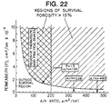
- the metabolic transit value takes into account the permeability value (P) and the porosity value (PORE) of the boundary 46.
- the permeability value (P) is the measure of the amount of solute that travels through the boundary per unit time and unit surface area, given some fixed external solute concentration (measured in cm/sec in this specification).
- Example 1 sets forth a methodology for determining the permeability value according to this aspect of the invention.
- the porosity value (PORE) represents the space in the boundary 46 that does not contain material, or is empty, or is composed of pores. Expressed as a percentage, the porosity value (PORE) measures the % volume of the boundary 46 that is not occupied by boundary material.
- PORE N ⁇ (d 2 /4)
- the permeability value is the principal influence upon the overall metabolic transit value. Still, below the threshold minimum porosity value, the metabolic transit value must also take into account the porosity value and the physical structure of the porous boundary 46. These considerations will be discussed later in greater detail.
- a boundary 46 To simplify the selection of a boundary 46, the inventors recommend the use of boundaries having a porosity value (PORE) greater than the observed minimum threshold value. Then, metabolic transit value and the permeability value can be treated as the same.
- PORE porosity value
- the assembly 100 includes a port member 102 that provides means for accessing the interior or cell chamber 104 of the assembly 100.
- the port member 102 is an elongated flexible tube 106.
- the elongated flexible tube is in fluid communication with the cell chamber 104 that is defined by the wall elements of the assembly.
- the port member 102 does not have to be defined by an elongated flexible tube.
- Other structures can be used to provide access to the cell chamber of the assembly.
- a resealable injection site can be provided on the assembly for providing access to the cell chamber.
- the port can be used to initially place cells 105 within the assembly 100.
- a syringe or other device can be used to place the cells within the cell chamber 104 defined by the assembly 100.
- the cannula of a syringe would be received by the flexible tube 106 allowing cells to be placed within the cell chamber 104.
- a syringe is utilized having a cannula that will be received within the full length of the port 102 and to an end 107 of the cell chamber 104 of the assembly.
- the syringe is slowly removed from the chamber. This methodology will insure that too great a pressure is not used that will damage the membrane as the tissue is laid. It is believed that the pressure used should be lower than syringe pressures. By using reduced pressure, additionally, this will insure that tissue is not damaged due to frictional forces that can shear the tissue if high pressures are utilized.
- the cells can initially be sealed within the assembly 100 as set forth above with respect to the embodiments of the assembly 100 not including a port.
- the port allows the assembly to be implanted without cells for prevascularization of the assembly.
- Prevascularization of the assembly is disclosed in U.S. patent application Serial No. 08/180,018 filed January 11, 1994 and PCT/US95/00321 (WO 95/18584) naming as inventors Steven Neuenfeldt, James Brauker, Robert Clarke, and Victoria Carr-Brandal.
- the assembly 100 includes at least one port 102, the assembly can be "recharged” by placing new cells within the assembly after a fixed period of time.
- the assembly 100 is implanted with the flexible tube 106 being located near the outer epidermal layers of the patient.
- a surgeon merely creates an incision in the skin exposing the end portion of the flexible tube 106. This allows the surgeon to thereby access the interior of the assembly 100 utilizing a syringe or other method for depositing new cells within the cell chamber 104 of the assembly 100 through the flexible tube 106.
- the tube 106 can then be sealed using a heat seal, mechanical means, or another method. The tube 106 is then placed within the patient and the incision is closed.
- a port can be used on any of the implant assemblies set forth in this application, as well as other implant assemblies.
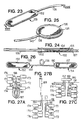
- the assembly 130 can comprise a disk-like device having an interior 136 with an 0-ring or hoop that defines a cell chamber.
- the disk defines an aperture 138 for sealingly receiving the port 140.
- the port 140 is an elongated flexible tube.
- an implant device 150 including two assemblies 152 and 154.
- the two assemblies 152 and 154 share a flexible tube 156 therebetween.
- the tube 156 is in fluid communication with the cell chambers 155 and 157 of each assembly 152 and 154.
- a first end 158 of the tube 156 is sealingly received by the assembly 152 and a second end 160 of the tube 156 is sealingly received by assembly 154.
- Such an implant device 150 allows a variety of different applications and methods of use of the assemblies 152 and 154.
- the device 150 can be implanted and prevascularized in the host. After the device 150, and specifically assemblies 152 and 154 are vascularized, the cell chambers 155 and 157 of same can be filled with cells. To this end, a surgeon will create an incision in the patient and access the tube 156. To aid the surgeon in locating the tube 156 a location clip can be attached to the tube. However, other means can be used to allow the surgeon to identify the approximate location of the tube prior to creating an incision in the patient, e.g., the tube can include at least portions thereof that are radiopaque and can thereby be located by an x-ray of the patient.
- each of the resultant tubes that are created will be in fluid communication with an interior of the respective assemblies 152 and 154. This will allow the surgeon to access the interior of the devices 152 and 154 and fill same with cells using a syringe or other means. The tubes are then sealed and replaced in the patient. The incision is then closed.
- the cells can be sealed within the assemblies 152 and 154 of the device 150 by heat sealing or other method when the device is created. After the device 150 is implanted, when necessary, the tube 156 can then be accessed and severed allowing the surgeon to recharge the assemblies 152 and 154.
- a ported device allows a plurality of implant assemblies 171-176 to be implanted in a patient and coupled together. Each of these ported implant assemblies can be charged either prior to being implanted into the patient or after implantation in the patient. Likewise, after a predetermined time, the assemblies can be charged to compensate for cells that are no longer viable or die.
- the respective tubes 181-186 of the assemblies can be clipped together with a location clip 187. This will allow the surgeon to easily locate and access the tubes 181-186.
- the clip 187 can act to seal the interiors of the tubes 181-186.
- the surgeon will make an incision and access the clip 187.
- the surgeon can access the interior of the tubes 181-186. This will allow the surgeon to fill each of the assemblies 171-176 with, for example, a syringe 189.
- the tubes 181-186 can be sealed again with the location clip 190. The tubes are then placed within the body 191 and the wound is closed. This allows the surgeon to easily and without a very invasive surgical procedure, to recharge the implanted assemblies 171-176.
- the length of the tube 106 should be selected so that it allows for multiple recharges of the assembly.
- the tube upon each recharge of the assembly, the tube will be resealed. This sealing process can be accomplished by utilizing a heat seal. Therefore, in accessing the interior of the assembly through the tube, it will be necessary for the surgeon to remove a portion of the tube. Accordingly, the length of the tube should be selected so as to allow a sufficient number of recharges during the useful life of the implanted assembly.
- the tube can be sealed using mechanical means, e.g., the tube can be clipped. This will allow a reduced length of tubing to be initially utilized since in order to access the tube, the clip is merely removed rather than a portion of the tube being sliced off. Additionally, the tube can be sealed by injecting a curable substrate into the interior of the tube, such as silicon, and allowing the substrate to seal as a plug.
- a curable substrate such as silicon
- the port can be sealed within the assembly pursuant to a number of methods. For example, ultrasonic welding, over-molding, or crimping can be utilized to create an implant assembly having a port.
- Figure 28 illustrates another assembly.
- the assembly 192 can include a port at both ends of the assembly. This will allow, if desired, the assembly's cell chamber to be flushed after each recharge.
- the assembly 192 thereby includes a first port 193 and a second port 194.
- Each port 193 and 194 is in fluid communication with the cell chamber 195.
- either port 193 or 194 can be designed to receive cells to be laid in the cell chamber 195 of the assembly 192.
- a fluid can be injected through port 193 by using a syringe. The original cells within the cell chamber 195 along with fluid would then exit the cell chamber through port 194.
- the cell chamber can be cleared prior to recharging.
- the cell chamber 104 can be cleaned through aspiration of the cells through the port 102.
- a syringe can be inserted into the cell chamber 104 through the port and a vacuum can be created to suction the cells present in the cell chamber into the syringe.
- the assembly 200 can include a spacer 202 for creating an area 204 within the interior of the assembly 200 for receiving the cells.
- the spacer circumscribes a majority of the perimeter of the assembly 200.
- the spacer or insert will maintain optimum cell depth, cell distribution, experimental pillow shape, and insure maximum chemical interactions. Cell space can be maintained in vivo prior to or following tissue loading using a filament or insert of approximate diameter equal to the desired tissue depth.
- the assembly 200 including the spacer 202 is illustrated without a port.
- the port would be received and sealed, in the illustrated embodiment, within the opening 206 at an end 208 of the assembly 200.
- the port can be used not only to deposit cells within the assembly, but to, if necessary, deliver nutrients or therapeutic agents to the cells within the assembly. Likewise, if necessary, the port can be used to aspirate a portion of, or all of, the implanted cells after the assembly has been implanted to modify the delivery of therapeutic agents by the assembly.
- the assembly can test the assembly prior to inserting cells into the assembly or implanting same. For example, if desired, the cells can be inserted into the assembly and therapeutic function can be evaluated prior to implantation.
- the present invention provides methods for adding cells to the implant assembly. Additionally, methods are provided for sealing the implant assembly after cells have been added thereto.
- a system 210 is provided that features an access catheter 212, a reservoir 214, and a pressure source 216.
- the reservoir 214 and pressure source 216 are defined by a syringe body and plunger and the access catheter 212 is a cannula.
- the system 210 located within the reservoir 214 are cells and a plug creating material 230. Accordingly, the system 210 provides a method for loading cells within an implant assembly and sealing an access opening of the assembly after the cells are so loaded.
- the method of the present invention allows the cells to be added to a device that is to be implanted, without damaging the cells. At the same time the method allows the device to be sealed so as to insure the integrity of the cell containing chamber and prevent cell egress from the device.
- a variety of different methods can be used to load the device with cells pursuant to the present invention.
- FIG 33 illustrates an example of a tissue loading system 210 of the present invention.
- the process steps that can be used to load an assembly 222 using the system 210 include the following.
- Tissue 218 is loaded in the reservoir 214.
- the tissue 218 can be loaded alone, or as discussed below with a fluid or matrix. However, the process will be described generally with respect to Figure 33 without reference to such fluid or matrix.
- the reservoir 214 includes a plug creating product 230.
- the plug creating product 230 is added to a back end 232 of the reservoir 214.
- the plug creating product 230 can be added to the back end of reservoir first and the tissue 218 can thereafter be added to the reservoir 214.
- the tissue 218 and plug creating material 230 are added to the reservoir 214, the tissue 218 can be loaded into an assembly 222, such as that illustrated in Figure 33.
- an assembly 222 such as that illustrated in Figure 33.
- the systems and methods of the present invention can be used to add tissue to any implant assembly and not only implant assemblies including ports.
- the port tube 224 is cleared.
- the catheter 212 is then inserted into the port tube 224 down to the interior end 234 of the device 222.
- either air pressure or syringe pressure can be applied to the back end of the reservoir 214.
- syringe pressure a variety of mechanisms can be used including, e.g., a syringe pump, mechanical screw, etc.
- the transfer mechanism can contain rate, position, and location controls.
- the tissue is added to the device 222 by being laid onto a bottom of the interior end 234 of the device 222.
- the catheter 212 is then slowly removed from the device 222. This allows tissue 218 to be added to the device 222 as the catheter 212 is removed. This method reduces pressure on the tissue 218 that can damage the tissue as it is added to the device 222.
- the catheter 212 can be moved from side to side. This allows the tissue 218 to be laid on a bottom floor of the interior of the device 222.
- the plug creating material 230 within the back of the reservoir will continue to fill the implant device 222 until visual verification is established in the port 228.
- the plug creating material 230 is added thereto so that a seal is created.
- the plug can be created by a variety of liquid materials that can be infused into the assembly or an access member of same, e.g., port, after the tissue is loaded into the assembly.
- a silicon plug is used to seal the port.
- a RTV or two-part silicon may be used.
- This material 230 in the embodiment of the system illustrated in Figure 33, would be located after the tissue product.
- a plug creating material can be used even if the systems of Figures 33 or 34 are not used.
- a separate reservoir can be used for the cells and the plug creating material.
- the resultant plug e.g., silicon plug, functions to isolate the tissue from the host.
- the use of the plug eliminates the need for further sealing of the port.
- the plug is used to seal off a port or tube, the plug can be used to seal off any access opening or portion of the assembly.
- the plug especially in combination with a ported device, provides a method for loading cells that greatly reduces, if not eliminates, cross contamination.
- a number of other closure or plug creating materials can be used other than a silicon plug including: polyurethane; epoxies; moisture curable compounds; cyanoacrylaides; curable polymers; curable elastomers; solid polymers with solvent based systems; and similar products that are sufficiently fluid and compatible to be used in an implant assembly.
- the plug creating material can included catalyst introduced to cure or gel a portion of the matrix.
- Matrix selection may feature a catalyst as readily available from the host via diffusion to assist in curing. For example, alginate's use of calcium is one example of such technology.
- fluid can be located at a front portion of reservoir in front of the tissue.
- the fluid can be used to open the device prior to the addition of the tissue. This will open the device so that the tissue can be added.
- a number of different fluids can be used including low density, low viscosity media, saline, or a number of other isotonic fluids.
- the tissue can be mixed with the fluid and then added to the device.
- the fluid/tissue segment should be such that the tissue comprises 1 to 100% of the fluid/tissue segment with the remaining portion being the fluid.
- a matrix located within the reservoir 214, in addition to cells (or tissue) can be a matrix.
- Figure 34 illustrates such a method and product, the matrix provides many functions when used to load cells in an implant assembly including: occupying dead space in the implant assembly; and restricting fibroblasts out-growth. Additionally, the matrix also protects the cells during loading.
- a tissue/matrix product wherein at least 25% and preferably, at least 50% of the tissue/matrix product that is loaded in the implant assembly comprises cells with the remaining portion of the product being the matrix. Therefore, a system is provided that allows at least 5 to 10 times as many cells, using a matrix, to be loaded into implant assemblies as heretofore possible. Indeed, the present invention, in an embodiment, provides at least 90% tissue with respect to the total amount of tissue/matrix to be loaded.
- the tissue prior to being loaded into the interior of the reservoir, is mixed with a matrix.
- the tissue is surrounded by the matrix creating a tissue/matrix product in the reservoir; which tissue/matrix product is then loaded into the implant assembly.
- tissue is loaded within the reservoir 314, and the matrix 320 is placed in juxtaposition to a back end 322 of the tissue 318.
- a plug creating material 330 is then located at a back end 332 of the matrix.
- matrices can be located in juxtaposition to both a front and back end of the tissue. This can be accomplished by back filling the reservoir 314 with a liquid matrix.
- a ported device 222 previously described with respect to Figure 23 is generally illustrated.
- tissue can be loaded into the interior 323 of the device 222 through the port 24.
- tissue once loaded within the device 222 can, for example, grow through opening 226 into the ported area 228.
- the ported area 228 will not support tissue growth.
- the matrix will protect the cells during loading.
- the matrix will protect the tissue from any shear forces caused by the syringe pressure.
- the tissue/matrix composition comprises at least 25% and preferably at least 50% tissue and in an embodiment, at least 90% tissue.
- the matrices can be selected from the group consisting of: alginate; agarose; poly[bis(carboxylatophenoxy) phosphazene (PCPP); sodium cellulose sulphate; methyl cellulose; chitosan; and carrageenans.
- Alginate is available from many sources, e.g., plant and bacterial derivates. A variety of alginate compositions can be used. Preferably, alginate will comprise 0.6% to 4.0% of the tissue/matrix composition with the remaining parts of the composition comprising tissue and, if desired, nutrients. In this regard, it should be noted that the tissue can be loaded into the assembly with nutrients. The nutrients can comprise 0% to 50% of the total product loaded into the implant device; in a typical embodiment, the nutrients will comprise approximately 10% of the total volume of product loaded into the implant assembly.
- Low-gelling temperature agarose can be used at a variety of levels, e.g., 5% of the total composition loaded into the implant assembly.
- Agarose containing the random copolymer hydroxemethacrylate-vinylbenzyl maltonamide and nicotinamide can be used in a preferred embodiment for the culturing of islet cell clusters.
- PCPP Poly[bis(carboxylatophenoxy)phosphazene
- W/V 2.5%
- Sodium cellulose sulphate can also be used as the matrix.
- sodium cellulose sulphate is used with a 2% precipitation bath (poly(dimethyldiallylammonium chloride) for micro-encapsulation of islets at 1.5% (W/V) of the composition that is loaded into the implant assembly.
- methyl cellulose also can be used as the matrix material.
- methyl cellulose is used in a composition at approximately 0.8% to about 40% of the total composition loaded into the implant assembly as a supporting gel matrix for cells in vitro.
- Carrageenans (high molecular weight, sulphated polygalactans, resembling agar) and desulphated carrageenans as noted above can also be used as a matrix material.
- the compounds are generally believed to down-regulate immune responses. The effect and the degree of the regulation of the immune response can vary between different carrageenans.
- High molecular weight carrageenan (>1x10⁵) is widely employed as a food additive as a consequence of its gelling and viscosity-building properties.
- All of the above matrices, in use, will fill voids in the implant assembly and establish a barrier between the host and new tissue.
- the reservoir 314 is loaded with tissue 318.
- the reservoir 314 is centrifuged to remove excess fluid. After centrifuging the reservoir 314, the excess fluid is removed from the reservoir.
- a matrix 320 is then added and a plug creating material 330 is then added to a back end of the reservoir 314.
- the system 310 is ready for device introduction or device loading.
- MCA-38 is a non-metastic cell line derived from a colon adenocarcinoma. The tumor was originally induced by subcutaneous injection of dimethylhydrazine into C57/B6 mice. The cells are maintained in culture supplemented with 10% fetal bovine serum, 1% L-glutamine (200 mM), 1% penicillin G (10,000 U/ml)/streptomycin (10,000 ⁇ g/ml), 1% Na Pyruvate (), 1% HEPES (1 mM) and 0.1% ⁇ -mercaptoethanol.
- B16 melanoma is a metastatic cell line also derived from C57/B6 mice.
- the cells are maintained in culture in DMEM supplemented with 20% fetal bovine serum, 1% L-glutamine (200 mM) and 1% penicillin G (10,000 U/ml)/streptomycin (10,000 ⁇ g/ml).
- tumor cells were removed from tissue culture flasks by trypsinization.
- the media was removed from the flask and the cells were washed twice with sterile HBSS and 2 ml of trypsin solution was added for 2-3 minutes.
- the cells were washed off of the flask with a pipette and transferred to fresh medium containing serum.
- the cells were counted and resuspended at a concentration of 10 6 cells/3 ⁇ l of medium.
- Tumor cells (10 6 cells in 3 ⁇ l growth medium) were loaded into several different devices. Cells were loaded into non-ported chambers (such as those illustrated in Figure 2). Cells were loaded into 4.5 ⁇ l ported devices (see Figure 23) using a Hamilton syringe as described for the in vitro assay above. Ported devices were sealed using either the silicon plug described above or by heat sealing with a heated hemostat used to pinch the port closed at several points along the length of the port. After heat sealing, excess port material was cut off.
- Non-ported chambers Devices containing MCA-38 cells were implanted into both epididymal fat pads and at subcutaneous sites of athymic or isogeneic mice. At time of explant (three weeks), the presence of tumor around the devices was noted. In athymic mice 8/16 (50%) devices containing MCA-38 cells had external tumors. In isogeneic animals 20/32 (62.5%) devices had external tumors when explanted at three weeks. For these two experiments, the overall failure rate of the non-ported chamber is 54% (see Figure 35). External tumor formed around devices at both implant sites. The frequency with which we observed these tumors suggested that the non-ported chamber is susceptible to loss of cells during the loading procedure. As an alternative, 4.5 ⁇ l ported device were evaluated.
- Ported devices In an experiment analogous to that described above, ported devices were loaded with MCA-38 cells and heat sealed by pressing on the port with a heated hemostat at several points. Excess port material was then cut off and the sealed end wiped with ethanol. Devices were then implanted into fat pad or subcutaneous sites of C57/B6 mice.
- non-ported chamber tested appears to be a leaky system; cells were able to escape from the majority of these devices. Since non-ported chambers are loaded by placing the cell suspension in the center of the bottom membrane and then covering with a second membrane before sealing, it is likely that these tumors were caused by cells which were squeezed out during friction sealing of the titanium rings. This sort of leak could easily lead to contamination of the assembly press as well.
- Example 2 shows that there is a direct correlation between the metabolic transit value and implanted cell survival during the ischemic period.
- Embryonic lungs enclosed in membrane chambers having different permeability values were implanted in subcutaneous sites in rats.
- the permeability values for the membrane chambers were obtained for insulin diffusion in a conventional benchtop diffusion chamber, made by Crown Glass Company, Somerville, New Jersey (Part Number DC-100), using radioactively labeled ( 125 I) insulin as the solute (obtained from ICN Biochemicals).
- the diffusion chamber had two chambers (which will be called Chambers A and B), each with a volume of 3 ml.
- the diffusion chamber presented a membrane surface area between the two chambers (where diffusion occurs) of 0.7 cm 2 .
- the practitioner cuts the membrane material to be tested to a predetermined, known size.
- the practitioner wets the membrane before conducting the permeability test, using conventional wetting techniques.
- the practitioner places the membrane in the diffusion chamber.
- the assembly of the diffusion chamber locates the membrane between the two chambers of equal volume, called Chamber A and Chamber B. In this way, the practitioner also fixes the cross sectional area (A) of the membrane.
- the diffusion chamber is uniformly heated to a temperature of about 37 degrees C during the test.
- the practitioner loads equal amounts of buffer solution into Chamber A and Chamber B.
- the buffer solution can vary.
- the practitioner can use phosphate buffered saline, 0.5% BSA as the buffer solution.
- Porcine pancreas insulin purchased from Sigma with an activity of 26.1 units/ml, or comparable material, can be used.
- the practitioner uniformly stirs the fluids within the chamber at about 600 RPM, using a magnetic stir plate and magnetic stir rods (about 1 cm in length) placed in each Chamber A and B. The practitioner allows the system to equilibrate for about one hour.
- the radioactive insulin suspension is filtered before use to remove free 125 I.
- Chamber A and Chamber B While stirring the fluids within Chamber A and Chamber B, the practitioner draws equal aliquots of fluid from each Chamber A and B (e.g. about 15 uL) at 2, 4, 6, 8, 10, 15, and 30 minute intervals.
- the practitioner determines the change in the counts (i.e., insulin concentration) in Chambers A and B per unit of time, suitably corrected for background noise.
- the practitioner graphs the count and time pairs for each Chamber in terms of time versus the counts (with the counts being the Y-coordinates and time being the X-coordinates), restricting the analysis to points for which the counts in Chamber B are less than about 10% of the initial counts in Chamber A.
- the practitioner then derives a linear equation, fitting the range of counts (y) over the set of times (x) for each Chamber according to the following equations:
- the practitioner preferably uses a commercially available computer program to simplify the derivation process described above.
- V b and A which remain constant throughout the test.
- dM b /dT the slope of the graph for Chamber B (N b ) from the linear equation derived for Chamber B.
- the practitioner converts the units of N b (counts per min/min) into counts per minute/sec by dividing by 60 (the number of seconds in a minute).
- the permeability value derived also includes the boundary layer effects that are associated with inevitable stagnate fluid layers at the membrane surface in Chambers A and B during the test. To arrive at the "true" intrinsic permeability value for the boundary, the practitioner would have to adjust for the boundary layer effects. However, for the purposes of this invention, a knowledge of the inherent membrane permeability is not essential, because it will be proportional to the experimental permeability value determined following the methodology detailed above.
- the disclosed methodology can be used to assess whether a given boundary fits the criteria established for the permeability value according to this aspect of the invention.
- the porosity values (PORE) of the boundaries tested ranged from less than about 15% to greater than about 70%.
- Embryonic lungs were removed from Lewis rat embryos between days 13.5 and 17.5 of development. The lungs were kept on ice in Dulbecco's Modified Eagle's Medium (DMEM), 20% fetal bovine serum. The lungs were minced until they were approximately 1 mm 2 . Minced lung tissue (5-10 ⁇ l) was placed into implant assemblies like those shown in Figs. 1 to 4. The lung tissue was encapsulated within test membranes having various permeabilities, porosities, and pore sizes. The implant assemblies were placed in DMEM (20% fetal bovine serum) at 37 degrees C until surgery, which occurred within 2 hours. The implant assemblies were implanted in subcutaneous or epididymal fat sites in male Lewis rats for 3 weeks.
- DMEM Dulbecco's Modified Eagle's Medium
- the assemblies were explanted, trimmed of excess fat, and fixed with 2% glutaraldehyde in Sorensen's buffer. Sections of the assemblies were stained with hematoxylin and eosin.
- Tissue survival was scored based upon histological appearance of the implanted cells. Tissues were scored as "excellent” if they had normal characteristics of lung tissue, such as epithelial tubules, cilia, and formed cartilage. Tissues were scored as "good” if the tissue were still alive, but not well differentiated (for example, a high number of mesenchymal cells). The tissues were scored as "poor” if no or few cells remained alive.
- survival assessment would involve analyzing the differentiated function of the pancreatic cells in terms of their insulin release in the response to a glucose challenge.
- Table 1 shows the permeability value for those boundaries having a porosity value (PORE) greater than 70%, correlated with the survival of the implanted lung tissues.
- PORE porosity value
- Table 2 shows the permeability value of those boundaries having a porosity value (PORE) less than 15%, correlated with the survival of the implanted cells.
- PORE porosity value
- Tables 1 and 2 demonstrate the direct relationship between the metabolic transit value of the boundary and implanted cell survival. More particularly, the Tables show that implanted cell survival significantly improves when the permeability value of the boundary increases.
- Example 1 The inventors believe that, when considering less porous boundaries, their specific physical structure must also be taken into account.
- the less porous interfaces used in Example 1 were track-etched membranes. These membranes have uniform cylindrical pores separated by relatively large, nonporous regions.
- the poor tissue survival using the low porosity boundaries could be due to uneven localization of areas of high permeability, or due to constraints produced by cells on the particular physical properties of the track-etched membranes.
- the cells may be more efficient at plugging up the cylindrical pores of the track-etched membranes either with cell extensions or cell secretions.
- the track-etched membranes have high permeability values in vitro, the response of the cells in vivo may prevent the attainment of sufficient metabolic transit to support the graft cells.
- Example 1 demonstrates a methodology that can be followed to identify for other cell types the applicable metabolic transit value that assures cell survival during the ischemic period after implantation.
- the absolute permeability and porosity values that constitute a given metabolic transport value will depend upon the type of cell and the methodologies of determining permeability and porosity. Different conditions will give different absolute values. Still, regardless of the test conditions, the relative differences in permeability and porosity values derived under constant, stated conditions will serve as an indicator of the relative capabilities of the boundaries to support implanted cell viability.
- Tables 1 and 2 also show that good tissue survival occurs even with membrane materials that are subject to the formation of an avascular fibrotic response (the so-called “foreign body capsule”).
- the fact that these membrane materials create this response has, in the past, led to the widely held view that the formation of the foreign body capsule caused poor diffusion of nutrients.
- Example 1 shows the error of this conventional wisdom.
- the thickness of the membrane does not alter the foreign body response; a foreign body capsule will form whether the membrane is relatively thick or thin. However, membrane thickness does alter the permeability value.
- the cells died when the thicker boundary was used, not because of the formation of the foreign body capsule, but because of poor nutrition and poor waste removal due to the low permeability of the thicker boundary.
- RAT-2 fibroblasts ATCC CRL 17644
- 20% Fetal Bovine Serum 2 mM 1-glutamine
- DMEM low glucose
- the cells were washed with 15 ml of HBSS (no ions) and trypsinized off the culture flask.
- the practitioner neutralized the trypsin by adding 5 ml of the above media.
- the practitioner pelleted the cells by centrifugation (1000 rpm, 10 minutes, at 22 degrees C).
- pelleted cells were counted and resuspended in media in three concentrations: 5.3 x 10 3 cells/10 ⁇ l; 5.8 x 10 5 cells/10 ⁇ l; and 5.8 x 10 6 cells/10 ⁇ l.
- Implant assemblies like that shown in Figs. 1 to 4 having boundaries of differing permeability values were made.
- the permeability values ranged from 0.2 x 10 -4 cm/sec to 9 x 10 -4 cm/sec (see Tables 1 and 2 to follow).
- the total boundary area for each assembly was about .77 cm 2 .
- the various cell concentrations were loaded into the assemblies.
- the practitioner implanted the assemblies both subcutaneously and within the epididymal fatpad of host rats.
- assemblies loaded with 5.8 x 10 3 cells and 5.8 x 10 5 cells displayed excellent results, given sufficient boundary permeability values. After 3 weeks of implantation, the initial load of 5.8 x 10 5 cells proliferated to approximately 2.0 x 10 7 cells. The inventors observed that assemblies having higher initial loads of 5.8 x 10 6 cells displayed poorer results.
- Neovascularization close to the boundary is essential to the long tern survival of the implanted cells within the host.
- the inventors have found that the host will not grow new vascular structures 54 close to the boundary (as Figs. 24 and 25 show), unless it is stimulated to do so. Without proper stimulation, the ischemic period never ends, because a classical foreign body reaction occurs.
- the assembly 10 therefore includes an angiogenic material 56 for stimulating neovascularization close to the boundary.
- the specific identity of the angiogenic material 56 is not known. Still, the inventors have determined that the presence of certain cells stimulate neovascularization, while others do not.
- lung tissues For example, the presence of lung tissues; pancreatic islets; adult pancreatic ducts; and cultured cell lines of fibroblasts, mammary gland, and smooth muscle cells induces or stimulates neovascularization, when compared to the vascularization on control grafts where these cell types were not present.
- the assembly 10 when cells are implanted that have a desired therapeutic effect, but do not secrete angiogenic material, the assembly 10 includes a separate angiogenic source cell or material 56.
- the practitioner selects an boundary 46 having a sufficient metabolic transit value to support the viability of the implanted cells, i.e., the angiogenic source cells and other non-angiogenic, therapeutic cells (when present) implanted with them.
- the practitioner also selects a pore size and ultimate physical strength to make the boundary 46 impermeable to the neovascular growth that the angiogenic source cells stimulate.
- the practitioner may coat the exterior of the boundary 46 itself with an angiogenic material 56.
- the coated boundary 46 still must have sufficient pore size, ultimate strength, and metabolic transit value to sustain the cells 12 isolated behind the boundary 46.
- the new vascular structures 54 cannot penetrate the boundary 46, and because the angiogenic signal to the host continues, the new vasculature proliferates close to the boundary 46.
- Fig. 21 shows, when the cells 12 die during the ischemic period, and close vascularization is not stimulated, the fibroblasts of the foreign body capsule 52 become closely packed and dense. However, as Fig. 20 shows, when the cells 12 survive the ischemic period, and the process of close vascularization is stimulated, the fibroblasts of the foreign body capsule 52 is altered to form a less dense and more dispersed structure.
- the porous boundary 46 includes an interface 47 with the host tissue that is characterized by a structural conformation that further enhances the growth of vascular structures by the host close to the boundary.
- each wall element 32/32' and 34/34' of the assemblies 10/10' includes a first porous region 58 and a different second porous region 60.
- the first porous region 58 comprises the boundary 46 previously described.
- the second porous region 60 comprises the interface 47.
- the first porous region 58 faces the implanted cells 12 (see Fig. 20).
- the first porous region 58 has the boundary characteristics, above described, of pore size; ultimate physical strength; and metabolic transit value. It is this region 58 that isolates the implanted cells from the immune mechanisms of the host, while sustaining their viability through the flux of nutrients and wastes during the ischemic period.
- the second porous region 60 faces the host tissue 44 and forms the interface 47 with it (see Fig. 20).
- the second porous region 60 has an architecture that enhances the formation of vascular structures 54 close to the boundary 46.
- the formation of these vascular structures 54 within the second region 60 mark the end of the ischemic period.
- Vascularization in the second region 60 sustains the viability of the implanted cells 12 after the ischemic period ends.
- a foreign body capsule 52 still forms about the implanted assembly 10. However, close vascularization within the second porous region 60 can alter the normal configuration of the foreign body capsule 52. As Fig. 20 shows, a life sustaining vascular bed forms within the capsule 52 close to the boundary 46, keeping flattened macrophages, foreign body giant cells, and fibroblasts from pressing against and blocking the boundary 46.
- the porous first region 58 Because of the pore size, strength, and permeability characteristics of the porous first region 58, it is impermeable to the neovasculature 54 formed in the second region 60.
- the inventors have observed by light and electron microscopy that close vascularization occurs if, in the initial period of implantation, at least some macrophages entering the material are not activated. Activated macrophage are characterized by cell flattening.
- the inventors observe close vascularization in regions of an implant where the macrophages that have entered the cavities of the material retain a rounded appearance when viewed through light microscopy ( ⁇ 400x). At 3000x (TEM) the rounded macrophage is observed to have substantially conformed to the contours of the material. Although there is a correlation with macrophage shape, it is not clear that macrophages control the observed, response. However, it is clear that invasion of the structure by host cells is required. Although the bulk of the cells appear to be macrophages, it is possible that other inflammatory cells control the response, therefore the inventors refer to the invading cells as "inflammatory cells,” which include but are not limited to macrophages.
- foreign body capsule formation occurs when, in the initial period of implantation, inflammatory cells in contact with the implant material flatten against those portions of the material which present an area amenable to such flattening behavior by an inflammatory cell.
- the material for the second region 60 that results in formation of close vascular structures is a polymer membrane having an average nominal pore size of approximately 0.6 to about 20 ⁇ m, using conventional methods for determination of pore size in the trade. Preferably, at least approximately 50% of the pores of the membrane have an average size of approximately 0.6 to about 20 ⁇ m.
- the structural elements which provide the three dimensional conformation may include fibers, strands, globules, cones or rods of amorphous or uniform geometry which are smooth or rough. These elements, referred to generally as "strands,” have in general one dimension larger than the other two and the smaller dimensions do not exceed five microns.
- the material consists of strands that define "apertures" formed by a frame of the interconnected strands.
- the apertures have an average size of no more than about 20 Am in any but the longest dimension.
- the apertures of the material form a framework of interconnected apertures, defining "cavities" that are no greater than an average of about 20 pn in any but the longest dimension.
- the material for the second region has at least some apertures having a sufficient size to allow at least some vascular structures to be created within the cavities. At least some of these apertures, while allowing vascular structures to form within the cavities, prevent connective tissue from forming therein because of size restrictions.
- Figs. 11 to 16 show a method of making a preferred embodiment of the wall elements 32 and 34 that forms the boundary.
- the method integrally joins material selected for the first region 58 to another material selected for the second region 60.
- the two joined materials form the composite, or laminated, structure 72 shared by both wall elements 32 and 34.
- the laminated structure 72 joins the interface 47 to the boundary 46.
- a porous PTFE membrane material having a thickness of about 35 microns and a pore size of about .4 micron is selected for the first region 58.
- This material is commercially available from Millipore Corporation under the tradename BioporeTM.
- the porous material selected for the first region 58 has a thickness of about 30 microns and an ultimate (tensile) strength value of at least 3700 PSI (2.5x10 7 Pascal), which is well above the desired minimum value.
- the selected material has pore size of .35 microns, which blocks the passage of inflammatory cells.
- the selected material has a permeability value for insulin of 2.6 x 10 -4 cm/sec and a porosity value of greater than 70%. The membrane therefore meets the metabolic transit value requirements.
- first region 58 polyethylene, polypropylene, cellulose acetate, cellulose nitrate, polycarbonate, polyester, nylon, and polysulfone materials can be used.
- Mixed esters of cellulose, polyvinylidene, difluoride, silicone, and polyacrylonitrile can also be used.
- a membrane material made by W.L. Gore and Associates (Elkton, Maryland) under the tradename Gore-TexTM is selected for the second region 60.
- the Gore-TexTM material comprises a microporous membrane made from PTFE.
- the membrane is 15 microns thick and has a pore size of 5 microns.
- Polyester strands 61 join the PTFE membrane to form a backing for it.
- the backing has a depth of about 120 microns.
- the Gore-TexTM material also has an ultimate strength value well above the desired minimum value.
- the conformation of the polyester strands 61 also meets the criteria, set forth earlier, for promoting the growth of neovascular structures.
- Step 1 the practitioner secures the edges of a strip of the Gore-TexTM material (second region 60) to a lamination slide 62, with the polyester backing 61 facing the slide 62.
- Step 2 the practitioner places 2 or 3 lamination slides 62 side-by-side on a work surface.
- a syringe 64 the practitioner applies cement or adhesive in continuous filaments 66 in a back and forth pattern across the lamination slides 62.
- Step 2 forms a criss-crossing pattern of cement filaments 66 across the secured strips of the second region material, as Fig. 13 shows.
- the cement selected can vary.
- the cement can be cellulose acetate or similar epoxy material.
- the cement comprises a mixture of Vynathene EY 90500 EVA resin and toluene (made by Mallinckrodt).
- the practitioner In forming the EVA cement mixture, the practitioner adds about 30 grams of resin and an equal amount of toluene to a bottle. The practitioner seals the bottle to allow the resin to dissolve. The bottle may be periodically shaken to accelerate this process.
- the relative amounts of resin and toluene may have to be slightly adjusted to arrive at the right consistency for the cement. If the cement is too thin to form continuous filaments when applied, use less toluene. If the cement is to viscous to be expressed from the syringe, use more toluene. Small changes in the amount of toluene added result is significant changes in the viscosity of the cement.
- Step 3 the practitioner places preformed strips of the BioporeTM membrane material (first region 58) upon the cement filaments 66 applied in Step 2.
- the practitioner precuts the BioporeTM membrane material into disks having the diameter desired for the wall elements 32 and 34.
- Step 4 the practitioner lays a strip of release material 68 (like Patapar) over the first region material 58 and covers the layered structure with another lamination slide 70.
- the practitioner clamps the lamination slides 62 and 70 together, bringing the membrane layers into intimate contact.
- Step 5 the practitioner places the clamped lamination slides 62 and 70 in an oven for about 5 to 10 minutes at a temperature of about 80 degrees C. The heat melts the EVA cement.
- Step 6 the heated lamination slides 62 and 70 are allowed to cool to room temperature. Upon cooling and solidification, the filaments 66 securely join the BioporeTM membrane material to the Gore-TexTM membrane material. The practitioner then unclamps the lamination slides 62 and 70 and removes the finished composite structure 72 (in strips).
- Step 7 the practitioner lays the composite structure 72 strips on a polypropylene cutting slab 74.
- the practitioner aligns a presized punch 76 over each precut disk, striking the punch with a hammer.
- the practitioner thereby frees the wall elements 32 or 34 formed of the composite structure of the desired dimensions.
- Small scissors may be used to snip any adherent polyester strands not cut by the die.
- Implant assemblies 10/10' are made using the wall elements in the manner previously described.
- first region material 58 can be applied to the second region material 60 by various alternative means to form the laminated structure 72.
- first region material 58 can be extruded in place upon the second region material 60.
- Each assembly presented a boundary area of about .77 cm 2 .
- Each assembly sustained an initial cell load of about 600 pancreatic islets (or about 600,000 pancreatic cells).
- the assemblies When implanted, the assemblies sustained cell densities of about 200,000 islets/cm 3 . These assemblies, made and used in accordance with the invention, supported 8 times more pancreatic islets in a given volume than the CytoTherapeutics assemblies (having cell densities of only 25,000 islets/cm 3 ).
- one aspect of the invention provides the ability to identify a metabolic transit value associated with a given cell type. Knowing the required metabolic transit value, in turn, makes it possible to identify the clinically practical region of operation, where compact implant assemblies can sustain therapeutically large volumes of cells.
- This aspect of the invention provides the methodology to derive and use a therapeutic loading factor (L) to characterize and predict the clinical effectiveness of a given implant assembly for a given cell type.
- L therapeutic loading factor
- the therapeutic loading factor (L) takes into account the number of cells (N) that are required to be implanted to achieve the desired therapeutic effect; the effective area (A) of the boundary between the implanted cells and host that the host can be reasonably expected to tolerate; and the metabolic transit value (T) needed to sustain cell viability.
- the permeability value (P) alone can be used to express the metabolic transit value (T).
- the observed ratio between the boundary area and the number of implanted cells (A/N c ) for the successful implantation of pancreatic cells was 128 ⁇ m 2 /pancreatic cell.
- the inventors believe that a somewhat larger ratio of about 150 ⁇ m 2 /pancreatic cell will provide a satisfactory margin for variance among different hosts.
- a permeability value (P) greater than about 1.5 x 10 -4 cm/sec for insulin should be provided a metabolic transit value that will sustain cell survival during the ischemic period and afterward.
- Fig. 22 shows the therapeutic loading curve for pancreatic cells generated based upon the above considerations.
- the curve displays the predicted region of cell survival in terms of the boundary area-to-cell number ratio A/N (x-coordinate) and permeability value P (y-coordinate) (given a porosity value of greater than about 15%).
- Fig. 22 predicts that assemblies operating to the right of the therapeutic loading curve will sustain implanted pancreatic cells. Fig. 22 predicts that assemblies operating to the left of the therapeutic loading curve will not.
- pancreatic islets or about 250 million pancreatic cells
- Table 3 lists a range of L's and D's at different A/N ratios for an implant assembly holding 250,000 pancreatic islets A/N A (cm 2 )/side L(cm) D(cm) 128 160 12.6 14.3 150 188 13.7 15.5 200 250 15.8 17.8 328 410 20.2 22.8 463 579 24.0 24.1
- A/N ratios less than about 200 ⁇ m 2 /pancreatic cell define the operating region of implant assemblies that offer compact, clinically practical implant boundary areas.
- Fig. 22 shows this preferred region.
- a practitioner can provide an implant assembly that combines the benefits of compact size with the ability to sustain the requisite therapeutical number of cells, by selecting a permeability value for the boundary that achieves a region of operation to the right of the therapeutic loading curve. The practitioner also selects the prescribed pore size and ultimate physical strength determined in accordance with the invention.
- Fig. 22 shows that the prior art hollow fiber implant assembly made by CytoTherapeutics (described in the Background section of this Specification) falls well outside the preferred region of clinically practical operation.
- This assembly offers an A/N ratio of about 328 ⁇ m 2 /pancreatic cell, about 1.5 times the A/N ratio of the invention.
- Fig. 22 also shows a prior art hollow fiber implant assembly made by W.R. Grace and Co. (Lexington, Ma), as reported by Proc. Natl. Acad. Sci. U.S.A., Vol. 88, pp. 11100-11104 (December 1991).
- Each hollow fiber had a length of 2-3 cm, and an inside diameter of 0.177 cm.
- the foregoing establishes a methodology to derive and use a therapeutic loading factor for pancreatic islets. This methodology can be followed to identify a therapeutic loading factor for other cell types and other ranges of metabolic transit values.
- the absolute value of the therapeutic loading factor derived will of course depend upon the type of cell and the methodologies used to determine permeability and porosity. Different conditions will give different absolute values for the therapeutic loading factor.
- PTFE membrane 5 ⁇ m PTFE membrane, GORE-TEX® L31324 from W.L. Gore and Associates, Inc. is an expanded polytetrafluoroethylene (PTFE) membrane with a pore size controlled to 5 ⁇ m. It has a nonwoven spunbound polyester backing layer as a support. Vender specification of membrane thickness is 0.006 ⁇ 0.002 inches (0.015 cm ⁇ 0.005 cm).
- PTFEE membrane BIOPORE® SF1R848E1 from Millipore Corporation is an expanded polytetrafluoroethylene, (PTFE) membrane with a pore size controlled to 0.4 ⁇ m. Vender specification of membrane thickness is 0.0009 ⁇ 0.0002 inches 0.002 ⁇ 0.0005 cm).
- Woven polyester, SAATIFIL® PES 290/50 from Saati Corporation is a woven polyester membrane made of polyester fibers. Vender specification of membrane thickness is 0.007 to 0.010 inches (0.018 to 0.025 cm).
- Membrane samples for field emission LVSEM analysis were prepared by mounting razor blade cut sections of each membrane on aluminum pin-type SEM specimen stubs. Avery Spot-O-GlueTM adhesive tabs were used to hold the samples in place. The mounted specimens were rimmed with silver adhesive paint for improved conductivity and imaging. The mounted specimens were vacuum sputter coated with palladium to enable reflectance of electrons during SEM observation.
Landscapes
- Health & Medical Sciences (AREA)
- Life Sciences & Earth Sciences (AREA)
- Chemical & Material Sciences (AREA)
- Engineering & Computer Science (AREA)
- Biomedical Technology (AREA)
- General Health & Medical Sciences (AREA)
- Transplantation (AREA)
- Veterinary Medicine (AREA)
- Public Health (AREA)
- Animal Behavior & Ethology (AREA)
- Dermatology (AREA)
- Medicinal Chemistry (AREA)
- Epidemiology (AREA)
- Oral & Maxillofacial Surgery (AREA)
- Botany (AREA)
- Chemical Kinetics & Catalysis (AREA)
- Heart & Thoracic Surgery (AREA)
- Cell Biology (AREA)
- Cardiology (AREA)
- Vascular Medicine (AREA)
- Zoology (AREA)
- Neurosurgery (AREA)
- Pharmacology & Pharmacy (AREA)
- Prostheses (AREA)
- Materials For Medical Uses (AREA)
- Electrotherapy Devices (AREA)
- Medicinal Preparation (AREA)
Applications Claiming Priority (3)
| Application Number | Priority Date | Filing Date | Title |
|---|---|---|---|
| US46492495A | 1995-06-05 | 1995-06-05 | |
| US464924 | 1995-06-05 | ||
| PCT/US1996/006891 WO1996039100A1 (en) | 1995-06-05 | 1996-05-15 | Tissue loading system for implantable biological devices |
Publications (2)
| Publication Number | Publication Date |
|---|---|
| EP0830106A1 EP0830106A1 (en) | 1998-03-25 |
| EP0830106B1 true EP0830106B1 (en) | 2002-04-10 |
Family
ID=23845813
Family Applications (1)
| Application Number | Title | Priority Date | Filing Date |
|---|---|---|---|
| EP96920211A Expired - Lifetime EP0830106B1 (en) | 1995-06-05 | 1996-05-15 | Tissue loading system for implantable biological devices |
Country Status (8)
| Country | Link |
|---|---|
| EP (1) | EP0830106B1 (da) |
| JP (1) | JPH11506951A (da) |
| AT (1) | ATE215800T1 (da) |
| CA (1) | CA2221142A1 (da) |
| DE (1) | DE69620602T2 (da) |
| DK (1) | DK0830106T3 (da) |
| ES (1) | ES2175101T3 (da) |
| WO (1) | WO1996039100A1 (da) |
Cited By (1)
| Publication number | Priority date | Publication date | Assignee | Title |
|---|---|---|---|---|
| EP3946148A1 (en) * | 2019-04-03 | 2022-02-09 | Vertex Pharmaceuticals Incorporated | Macroencapsulation devices |
Families Citing this family (5)
| Publication number | Priority date | Publication date | Assignee | Title |
|---|---|---|---|---|
| USD720469S1 (en) | 2013-03-07 | 2014-12-30 | Viacyte, Inc. | Cell encapsulation device |
| AU2014225352B2 (en) * | 2013-03-07 | 2017-02-09 | Viacyte, Inc. | 3-dimensional large capacity cell encapsulation device assembly |
| JP6701192B2 (ja) | 2014-11-20 | 2020-05-27 | ヴィアサイト インコーポレイテッド | 移植可能デバイスに細胞を装填するための機器および方法 |
| CA3042495A1 (en) | 2016-11-10 | 2018-05-17 | Viacyte, Inc. | Pdx1 pancreatic endoderm cells in cell delivery devices and methods thereof |
| JP6888150B2 (ja) * | 2020-04-30 | 2021-06-16 | ヴィアサイト インコーポレイテッド | 移植可能デバイスに細胞を装填するための機器および方法 |
Family Cites Families (10)
| Publication number | Priority date | Publication date | Assignee | Title |
|---|---|---|---|---|
| US4309776A (en) * | 1980-05-13 | 1982-01-12 | Ramon Berguer | Intravascular implantation device and method of using the same |
| NO165378C (no) * | 1985-11-22 | 1991-02-06 | Ellingsen O & Co | Medikamentavgivende innretning for implantering i menneskekroppen. |
| US4911717A (en) * | 1987-06-18 | 1990-03-27 | Gaskill Iii Harold V | Intravasular artificial organ |
| US4810246A (en) * | 1987-11-04 | 1989-03-07 | L. Vad Technology, Inc. | Disposable cell culture chamber with remote access |
| US5314471A (en) * | 1991-07-24 | 1994-05-24 | Baxter International Inc. | Tissue inplant systems and methods for sustaining viable high cell densities within a host |
| WO1993021902A1 (en) * | 1992-04-24 | 1993-11-11 | Somatix Therapy Corporation | Biocompatible, therapeutic, implantable device |
| US5469867A (en) * | 1992-09-02 | 1995-11-28 | Landec Corporation | Cast-in place thermoplastic channel occluder |
| US5262055A (en) * | 1992-10-19 | 1993-11-16 | The University Of Utah | Implantable and refillable biohybrid artificial pancreas |
| US5549675A (en) * | 1994-01-11 | 1996-08-27 | Baxter International, Inc. | Method for implanting tissue in a host |
| WO1995018583A1 (en) * | 1994-01-11 | 1995-07-13 | Baxter International Inc. | Ported tissue implant systems and methods of using same |
-
1996
- 1996-05-15 ES ES96920211T patent/ES2175101T3/es not_active Expired - Lifetime
- 1996-05-15 JP JP9500566A patent/JPH11506951A/ja active Pending
- 1996-05-15 DK DK96920211T patent/DK0830106T3/da active
- 1996-05-15 AT AT96920211T patent/ATE215800T1/de not_active IP Right Cessation
- 1996-05-15 WO PCT/US1996/006891 patent/WO1996039100A1/en not_active Ceased
- 1996-05-15 CA CA002221142A patent/CA2221142A1/en not_active Abandoned
- 1996-05-15 DE DE69620602T patent/DE69620602T2/de not_active Expired - Fee Related
- 1996-05-15 EP EP96920211A patent/EP0830106B1/en not_active Expired - Lifetime
Cited By (1)
| Publication number | Priority date | Publication date | Assignee | Title |
|---|---|---|---|---|
| EP3946148A1 (en) * | 2019-04-03 | 2022-02-09 | Vertex Pharmaceuticals Incorporated | Macroencapsulation devices |
Also Published As
| Publication number | Publication date |
|---|---|
| WO1996039100A1 (en) | 1996-12-12 |
| EP0830106A1 (en) | 1998-03-25 |
| DE69620602D1 (de) | 2002-05-16 |
| ATE215800T1 (de) | 2002-04-15 |
| DK0830106T3 (da) | 2002-07-29 |
| DE69620602T2 (de) | 2002-11-21 |
| JPH11506951A (ja) | 1999-06-22 |
| ES2175101T3 (es) | 2002-11-16 |
| CA2221142A1 (en) | 1996-12-12 |
Similar Documents
| Publication | Publication Date | Title |
|---|---|---|
| US5545223A (en) | Ported tissue implant systems and methods of using same | |
| US5713888A (en) | Tissue implant systems | |
| EP0633755B1 (en) | Systems for cells implants | |
| EP0676935B1 (en) | Angiogenic tissue implant systems | |
| US5653756A (en) | Closed porous chambers for implanting tissue in a host | |
| US6773458B1 (en) | Angiogenic tissue implant systems and methods | |
| US5453278A (en) | Laminated barriers for tissue implants | |
| WO1996032076A1 (en) | Tissue implant systems | |
| AU645155B2 (en) | Close vascularization implant material | |
| CA2190628C (en) | An implantable containment apparatus for a therapeutical device and method for loading and reloading the device therein | |
| US6426214B1 (en) | Cell encapsulating device containing a cell displacing core for maintaining cell viability | |
| EP0688196B1 (en) | Ported tissue implant systems | |
| CA2156732A1 (en) | Method for implanting tissue in a host | |
| JPH10503965A (ja) | 治療用デバイスのための移植可能な閉じ込め装置並びにその中にそのデバイスを装填及び再装填する方法 | |
| CA2121040A1 (en) | Prevascularized polymeric implants for organ transplantation | |
| CA2140905A1 (en) | Use of pouch of implantation of living cells | |
| EP0830106B1 (en) | Tissue loading system for implantable biological devices | |
| Lahooti et al. | Agarose enhances the viability of intraperitoneally implanted microencapsulated L929 fibroblasts | |
| CN118338865A (zh) | 开放式可植入细胞递送装置 | |
| TR2025016045A1 (tr) | Subkutan İmmünomodülatör Ve İmmünomonitor Sistem: Hücre Geçirgen Zar Yapısına Sahip, İnaktive Tümör Ve İmmün Hücre Barındıran Örnek Alma Ve Çoklu Kompartman Etkileşim Yeteneğine Sahip Biyoimplant Platformu | |
| Smith et al. | Biomaterials in liver tissue engineering |
Legal Events
| Date | Code | Title | Description |
|---|---|---|---|
| PUAI | Public reference made under article 153(3) epc to a published international application that has entered the european phase |
Free format text: ORIGINAL CODE: 0009012 |
|
| 17P | Request for examination filed |
Effective date: 19971223 |
|
| AK | Designated contracting states |
Kind code of ref document: A1 Designated state(s): AT BE CH DE DK ES FR GB IE IT LI NL SE |
|
| 17Q | First examination report despatched |
Effective date: 20001129 |
|
| GRAG | Despatch of communication of intention to grant |
Free format text: ORIGINAL CODE: EPIDOS AGRA |
|
| GRAG | Despatch of communication of intention to grant |
Free format text: ORIGINAL CODE: EPIDOS AGRA |
|
| GRAG | Despatch of communication of intention to grant |
Free format text: ORIGINAL CODE: EPIDOS AGRA |
|
| GRAH | Despatch of communication of intention to grant a patent |
Free format text: ORIGINAL CODE: EPIDOS IGRA |
|
| REG | Reference to a national code |
Ref country code: GB Ref legal event code: IF02 |
|
| GRAH | Despatch of communication of intention to grant a patent |
Free format text: ORIGINAL CODE: EPIDOS IGRA |
|
| GRAA | (expected) grant |
Free format text: ORIGINAL CODE: 0009210 |
|
| AK | Designated contracting states |
Kind code of ref document: B1 Designated state(s): AT BE CH DE DK ES FR GB IE IT LI NL SE |
|
| REF | Corresponds to: |
Ref document number: 215800 Country of ref document: AT Date of ref document: 20020415 Kind code of ref document: T |
|
| REG | Reference to a national code |
Ref country code: CH Ref legal event code: EP |
|
| PGFP | Annual fee paid to national office [announced via postgrant information from national office to epo] |
Ref country code: GB Payment date: 20020515 Year of fee payment: 7 |
|
| REG | Reference to a national code |
Ref country code: IE Ref legal event code: FG4D |
|
| REF | Corresponds to: |
Ref document number: 69620602 Country of ref document: DE Date of ref document: 20020516 |
|
| PGFP | Annual fee paid to national office [announced via postgrant information from national office to epo] |
Ref country code: FR Payment date: 20020517 Year of fee payment: 7 |
|
| PGFP | Annual fee paid to national office [announced via postgrant information from national office to epo] |
Ref country code: DE Payment date: 20020520 Year of fee payment: 7 Ref country code: AT Payment date: 20020520 Year of fee payment: 7 |
|
| PGFP | Annual fee paid to national office [announced via postgrant information from national office to epo] |
Ref country code: SE Payment date: 20020521 Year of fee payment: 7 Ref country code: DK Payment date: 20020521 Year of fee payment: 7 Ref country code: CH Payment date: 20020521 Year of fee payment: 7 |
|
| PGFP | Annual fee paid to national office [announced via postgrant information from national office to epo] |
Ref country code: NL Payment date: 20020522 Year of fee payment: 7 |
|
| PGFP | Annual fee paid to national office [announced via postgrant information from national office to epo] |
Ref country code: IE Payment date: 20020530 Year of fee payment: 7 |
|
| PGFP | Annual fee paid to national office [announced via postgrant information from national office to epo] |
Ref country code: ES Payment date: 20020606 Year of fee payment: 7 |
|
| REG | Reference to a national code |
Ref country code: CH Ref legal event code: NV Representative=s name: KIRKER & CIE SA |
|
| PGFP | Annual fee paid to national office [announced via postgrant information from national office to epo] |
Ref country code: BE Payment date: 20020711 Year of fee payment: 7 |
|
| ET | Fr: translation filed | ||
| REG | Reference to a national code |
Ref country code: DK Ref legal event code: T3 |
|
| REG | Reference to a national code |
Ref country code: ES Ref legal event code: FG2A Ref document number: 2175101 Country of ref document: ES Kind code of ref document: T3 |
|
| PLBE | No opposition filed within time limit |
Free format text: ORIGINAL CODE: 0009261 |
|
| STAA | Information on the status of an ep patent application or granted ep patent |
Free format text: STATUS: NO OPPOSITION FILED WITHIN TIME LIMIT |
|
| 26N | No opposition filed |
Effective date: 20030113 |
|
| PG25 | Lapsed in a contracting state [announced via postgrant information from national office to epo] |
Ref country code: IE Free format text: LAPSE BECAUSE OF NON-PAYMENT OF DUE FEES Effective date: 20030515 Ref country code: GB Free format text: LAPSE BECAUSE OF NON-PAYMENT OF DUE FEES Effective date: 20030515 Ref country code: AT Free format text: LAPSE BECAUSE OF NON-PAYMENT OF DUE FEES Effective date: 20030515 |
|
| PG25 | Lapsed in a contracting state [announced via postgrant information from national office to epo] |
Ref country code: SE Free format text: LAPSE BECAUSE OF NON-PAYMENT OF DUE FEES Effective date: 20030516 Ref country code: ES Free format text: LAPSE BECAUSE OF NON-PAYMENT OF DUE FEES Effective date: 20030516 |
|
| PG25 | Lapsed in a contracting state [announced via postgrant information from national office to epo] |
Ref country code: LI Free format text: LAPSE BECAUSE OF NON-PAYMENT OF DUE FEES Effective date: 20030531 Ref country code: CH Free format text: LAPSE BECAUSE OF NON-PAYMENT OF DUE FEES Effective date: 20030531 Ref country code: BE Free format text: LAPSE BECAUSE OF NON-PAYMENT OF DUE FEES Effective date: 20030531 |
|
| BERE | Be: lapsed |
Owner name: *BAXTER INTERNATIONAL INC. Effective date: 20030531 |
|
| PG25 | Lapsed in a contracting state [announced via postgrant information from national office to epo] |
Ref country code: NL Free format text: LAPSE BECAUSE OF NON-PAYMENT OF DUE FEES Effective date: 20031201 Ref country code: DK Free format text: LAPSE BECAUSE OF NON-PAYMENT OF DUE FEES Effective date: 20031201 |
|
| PG25 | Lapsed in a contracting state [announced via postgrant information from national office to epo] |
Ref country code: DE Free format text: LAPSE BECAUSE OF NON-PAYMENT OF DUE FEES Effective date: 20031202 |
|
| REG | Reference to a national code |
Ref country code: DK Ref legal event code: EBP |
|
| EUG | Se: european patent has lapsed | ||
| GBPC | Gb: european patent ceased through non-payment of renewal fee |
Effective date: 20030515 |
|
| REG | Reference to a national code |
Ref country code: CH Ref legal event code: PL |
|
| PG25 | Lapsed in a contracting state [announced via postgrant information from national office to epo] |
Ref country code: FR Free format text: LAPSE BECAUSE OF NON-PAYMENT OF DUE FEES Effective date: 20040130 |
|
| NLV4 | Nl: lapsed or anulled due to non-payment of the annual fee |
Effective date: 20031201 |
|
| REG | Reference to a national code |
Ref country code: FR Ref legal event code: ST |
|
| REG | Reference to a national code |
Ref country code: IE Ref legal event code: MM4A |
|
| REG | Reference to a national code |
Ref country code: ES Ref legal event code: FD2A Effective date: 20030516 |
|
| PG25 | Lapsed in a contracting state [announced via postgrant information from national office to epo] |
Ref country code: IT Free format text: LAPSE BECAUSE OF NON-PAYMENT OF DUE FEES;WARNING: LAPSES OF ITALIAN PATENTS WITH EFFECTIVE DATE BEFORE 2007 MAY HAVE OCCURRED AT ANY TIME BEFORE 2007. THE CORRECT EFFECTIVE DATE MAY BE DIFFERENT FROM THE ONE RECORDED. Effective date: 20050515 |