EP0830264B1 - Dispositif pour relier un bras leve-vitre a la vitre mobile de la fenetre d'un vehicule a moteur - Google Patents
Dispositif pour relier un bras leve-vitre a la vitre mobile de la fenetre d'un vehicule a moteur Download PDFInfo
- Publication number
- EP0830264B1 EP0830264B1 EP96920687A EP96920687A EP0830264B1 EP 0830264 B1 EP0830264 B1 EP 0830264B1 EP 96920687 A EP96920687 A EP 96920687A EP 96920687 A EP96920687 A EP 96920687A EP 0830264 B1 EP0830264 B1 EP 0830264B1
- Authority
- EP
- European Patent Office
- Prior art keywords
- clamping
- window pane
- guide profile
- areas
- window
- Prior art date
- Legal status (The legal status is an assumption and is not a legal conclusion. Google has not performed a legal analysis and makes no representation as to the accuracy of the status listed.)
- Expired - Lifetime
Links
- 229920001971 elastomer Polymers 0.000 claims description 7
- 239000004033 plastic Substances 0.000 claims description 7
- 229920003023 plastic Polymers 0.000 claims description 7
- 239000005060 rubber Substances 0.000 claims description 7
- 229910000831 Steel Inorganic materials 0.000 claims description 3
- 239000000463 material Substances 0.000 claims description 3
- 239000010959 steel Substances 0.000 claims description 3
- 239000013013 elastic material Substances 0.000 claims description 2
- 238000005516 engineering process Methods 0.000 claims description 2
- 230000005484 gravity Effects 0.000 claims description 2
- 238000007493 shaping process Methods 0.000 claims 1
- 230000008878 coupling Effects 0.000 description 2
- 238000010168 coupling process Methods 0.000 description 2
- 238000005859 coupling reaction Methods 0.000 description 2
- 238000006073 displacement reaction Methods 0.000 description 2
- 238000009434 installation Methods 0.000 description 2
- 238000004026 adhesive bonding Methods 0.000 description 1
- 238000010276 construction Methods 0.000 description 1
- 238000000034 method Methods 0.000 description 1
- 239000003973 paint Substances 0.000 description 1
Images


Classifications
-
- E—FIXED CONSTRUCTIONS
- E05—LOCKS; KEYS; WINDOW OR DOOR FITTINGS; SAFES
- E05F—DEVICES FOR MOVING WINGS INTO OPEN OR CLOSED POSITION; CHECKS FOR WINGS; WING FITTINGS NOT OTHERWISE PROVIDED FOR, CONCERNED WITH THE FUNCTIONING OF THE WING
- E05F11/00—Man-operated mechanisms for operating wings, including those which also operate the fastening
- E05F11/38—Man-operated mechanisms for operating wings, including those which also operate the fastening for sliding windows, e.g. vehicle windows, to be opened or closed by vertical movement
- E05F11/382—Man-operated mechanisms for operating wings, including those which also operate the fastening for sliding windows, e.g. vehicle windows, to be opened or closed by vertical movement for vehicle windows
- E05F11/385—Fixing of window glass to the carrier of the operating mechanism
-
- E—FIXED CONSTRUCTIONS
- E05—LOCKS; KEYS; WINDOW OR DOOR FITTINGS; SAFES
- E05F—DEVICES FOR MOVING WINGS INTO OPEN OR CLOSED POSITION; CHECKS FOR WINGS; WING FITTINGS NOT OTHERWISE PROVIDED FOR, CONCERNED WITH THE FUNCTIONING OF THE WING
- E05F11/00—Man-operated mechanisms for operating wings, including those which also operate the fastening
- E05F11/38—Man-operated mechanisms for operating wings, including those which also operate the fastening for sliding windows, e.g. vehicle windows, to be opened or closed by vertical movement
- E05F11/44—Man-operated mechanisms for operating wings, including those which also operate the fastening for sliding windows, e.g. vehicle windows, to be opened or closed by vertical movement operated by one or more lifting arms
- E05F11/445—Man-operated mechanisms for operating wings, including those which also operate the fastening for sliding windows, e.g. vehicle windows, to be opened or closed by vertical movement operated by one or more lifting arms for vehicle windows
-
- E—FIXED CONSTRUCTIONS
- E05—LOCKS; KEYS; WINDOW OR DOOR FITTINGS; SAFES
- E05F—DEVICES FOR MOVING WINGS INTO OPEN OR CLOSED POSITION; CHECKS FOR WINGS; WING FITTINGS NOT OTHERWISE PROVIDED FOR, CONCERNED WITH THE FUNCTIONING OF THE WING
- E05F15/00—Power-operated mechanisms for wings
- E05F15/60—Power-operated mechanisms for wings using electrical actuators
- E05F15/603—Power-operated mechanisms for wings using electrical actuators using rotary electromotors
- E05F15/665—Power-operated mechanisms for wings using electrical actuators using rotary electromotors for vertically-sliding wings
- E05F15/689—Power-operated mechanisms for wings using electrical actuators using rotary electromotors for vertically-sliding wings specially adapted for vehicle windows
-
- E—FIXED CONSTRUCTIONS
- E05—LOCKS; KEYS; WINDOW OR DOOR FITTINGS; SAFES
- E05Y—INDEXING SCHEME ASSOCIATED WITH SUBCLASSES E05D AND E05F, RELATING TO CONSTRUCTION ELEMENTS, ELECTRIC CONTROL, POWER SUPPLY, POWER SIGNAL OR TRANSMISSION, USER INTERFACES, MOUNTING OR COUPLING, DETAILS, ACCESSORIES, AUXILIARY OPERATIONS NOT OTHERWISE PROVIDED FOR, APPLICATION THEREOF
- E05Y2600/00—Mounting or coupling arrangements for elements provided for in this subclass
- E05Y2600/50—Mounting methods; Positioning
- E05Y2600/502—Clamping
-
- E—FIXED CONSTRUCTIONS
- E05—LOCKS; KEYS; WINDOW OR DOOR FITTINGS; SAFES
- E05Y—INDEXING SCHEME ASSOCIATED WITH SUBCLASSES E05D AND E05F, RELATING TO CONSTRUCTION ELEMENTS, ELECTRIC CONTROL, POWER SUPPLY, POWER SIGNAL OR TRANSMISSION, USER INTERFACES, MOUNTING OR COUPLING, DETAILS, ACCESSORIES, AUXILIARY OPERATIONS NOT OTHERWISE PROVIDED FOR, APPLICATION THEREOF
- E05Y2900/00—Application of doors, windows, wings or fittings thereof
- E05Y2900/50—Application of doors, windows, wings or fittings thereof for vehicles
- E05Y2900/53—Type of wing
- E05Y2900/55—Windows
Definitions
- the invention relates to a device for connecting a Arm window lifter with the sliding window pane of a motor vehicle according to the preamble of claim 1.
- DE-31 08 244 A1 is a snap-on connection device between a window pane of a motor vehicle and a window lifter known from two together connected channel-like profiles, of which the one encloses an area of the lower edge of the pane and is attached there.
- the other downward open profile bears inward-facing hooks at its ends, which with Projections of angle elements of the lifting device in Can engage, creating a positive connection is achievable. Snapping the fasteners is by moving the window pane against the forced upper stop position, causing a automatic alignment of the window pane in the frame construction takes place and additional handles during the Assembly is not necessary.
- DE 29 23 039 C2 is in the area of the lower edge the window rail fastened by gluing known, in the lower part executed as a C-profile the glides of the lever arms of a cross arm window regulator are guided.
- the connection of the window regulator with the window pane is done by means of screw connections.
- the assembly of this lifting rail is also outside the door.
- US-C-4,866,895 describes a connector with a one-piece plastic part, which in the area of Lower edge of the pane and by means of a pane hole clips can be attached.
- This plastic part bears resilient wings on both sides, which recesses are assigned to the lifting rail, in which the wings are Snap assembly into place.
- the disadvantage of this The solution is the comparatively low resilience the connecting device because the plastic at higher temperatures tend to flow and thus only low Deduction forces can transfer.
- connection device known from JP-A-6-221052 is also a plastic part that is made using a disc hole attached in the area of the lower edge of the pane in a clip-on manner can be.
- the lifting rail is attached by a screw through the plastic part as well as that Screw hole is screwed.
- the invention has for its object a device for connecting an arm window lifter with the sliding one Developing a motor vehicle window pane with simple means of assembly and simultaneous adjustment a window pane inside the vehicle door allows with the window pane no pre-assembled attachments should wear.
- the task is characterized by Features of claim 1 solved.
- the clamping area is a separate one Clamping jaw and a clamping device, preferably a screw, assigned. Between the clamping areas of the guide profile and the separate jaws will be the window pane introduced until their edge against assigned stops bumps. After tightening the connector the window pane is attached by friction.
- the guide profile like the separate clamping jaws, for example made of steel as a stamped / embossed part be.
- the gap between the Clamping area and the jaw is an elastic material arranged with a high coefficient of friction that the Encloses the edge of the pane on both sides in this area.
- rubber has proven to be particularly practical.
- the guide profile can also be designed as a plastic part be, at least the clamping areas using outsert technology should be carried out to the occurring forces to be able to transfer.
- clamping axis can also be essentially horizontal if the contour of the window pane to which the Guide profile should be connected, runs vertically.
- Another preferred variant of the invention provides for one Cross arm windows in front, only the clamping area at the edge of the Arrange leadership profile on the side of the leadership backdrop for a glider of a lever arm or - if available of two leadership scenes - on the side of the longer management backdrop.
- the second clamping area is between the guide link and the joint point of the other Lever arm or arranged between the two guide links.
- the guide profile carries a during assembly spring acting in the direction of displacement of the window pane, the spring being as far as possible from the center of gravity the window pane should have.
- the spring forms one of the two support points for the pane edge and is not or not from the disc weight occurring there deformed so much that the edge of the window stops lies.
- the constructive design of the window regulator system is Assert the desired benefits of the spring in such a way make that the disc contour lying over the spring in front of the contour on the other side in the window frame drives in. With a further increase in pressure the spring is increasingly deformed up to the disc contour the other side lies against the frame. Subsequently the clamp connections can be clamped, which completes the assembly and adjustment process. The travel is corresponding preselect the expected tolerances.
- the spring is preferably directly in the clamping area arranged.
- it can be designed as a leaf spring and at special exhibitions of the leadership profile be fixed, with the exhibitions also serving as end stops to serve.
- Spring in the base area of a U-shaped rubber element integrate that grips the lower edge of the pane and on the Guide profile is supported.
- the connecting device according to the invention is also for a single arm window regulator applicable. Only that one described use of a spring element for the purpose of automatic adjustment of the window pane in a door frame is not practical with a single arm window regulator.
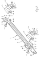
- this consists of a Guide profile 1 with a guide channel 11 for the glider 110 of a lever arm 6a and a bearing bush 12 for the Bearing pin 120 of the other lever arm 6b, two separate Clamping jaws 2, which are integrally attached to the guide profile 1 molded clamping area 10a, 10b are assigned, and Screws 15 for clamping the jaws 2 and clamping areas 10a, 10b.
- profile rubbers 3 are also provided, between the clamping areas 10a, 10b and Store jaws 2 and on their upper free ends be plugged on.
- the guide profile 1 shown is a one-piece Stamped / embossed part made of steel and integrated next to the already mentioned functional areas 10a, 10b, 11, 12 also the Stops 13, 14 for the pane edge and the eyelets 121, the one in cooperation with the lugs 21 Form an anti-twist device for the separate clamping jaws 2.
- the stop 14 consists of a Pair of flags emerging from the material towards the separate jaw 2 are bent out and the clamping area Flank 10b on both sides. They serve at the same time to hold the arched towards the window Leaf spring 4, which in turn acts as a stop for the The lower edge of the pane serves.
- the separate clamping jaws 2 are also designed as stamped parts and have a front clamping surface 20. Between the nose 21 and the clamping surface 20 is a nut 215 (weld nut or press nut) arranged in the Thread opening 200, the screw 15 is screwed in the opening 100 below the clamping area 10a, 10b reaches through. When tightening the screw connection 15, 215 the jaw 2 is supported in the area of its nose 121 Guide profile 1 from. On the other hand, the clamping areas 10a, 10b and 20 with the interposition of the tread rubber 3 the surfaces of the window pane (not shown) pressed. The clamping areas 10, 20 and the screw 15 or the nut 215 and the eyelet 121 or the nose 21 The clamping axis formed is essentially orthogonal assigned to the running edge of the pane at which the Clamping should take place.
- the cross arm window lifter consisting of the base plate 62, a motor-gear unit 63 mounted thereon, their (not visible) drive pinion into the toothing one also on the base plate 62 in the swivel joint 600 engages pivotally attached toothed segment 61.
- the Tooth segment 61 is firmly connected to the lever arm 6a, the opposite end of which rests on a bolt 111 carries a slider 110 which is slidable in the guide channel 11, the bolt 111 carrying the slider 110 passes through the backdrop 11a.
- the slider 550 on the one hand in the guide channel 55 of the guide rail 5
- the bolt 120 on the other hand in the bearing bush 12 of the guide profile 1 locked.
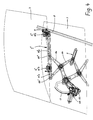
- Figures 3a and 3b show a schematic representation a variant of the invention with a clamping axis (formed by the parts or areas 21 ', 121' and 15 'and 10', 20 '), that in the longitudinal axis of the guide profile 1 ', ie horizontally runs.
- the clamping areas 10'a, 10'b, 20 ' vertically running edges 71 of the fastening wing 70 assigned that down on the window pane 7 extends.
- the guide profile 1 ' corresponds to that in FIGS. 1 and 2 described guide profile 1.
- FIG. 4 shows a connecting device with two guide areas 11''a, 11''b, between which the clamping area 10''b is arranged.
- a slider 9 in Connection that is form-fitting and movable in one extending along the displacement path of the window pane 7
- Guide rail 8 engages. So the kinematics of the Window trigger not from the cross arm window lifter, but from the guide rail 8 determines.
- the bolt 120 '' of the lever arm 6b on left stop of the backdrop 11''b and moves in Direction of the right stop when the window pane 7 is moved to the lower position.
Landscapes
- Window Of Vehicle (AREA)
Abstract
Claims (12)
- Dispositif pour relier un bras lève-vitre à la vitre mobile (7) de la fenêtre d'un véhicule à moteur, en utilisant un profil de guidage (1, 1', 1'') qui est fixé dans la région du bord (71) de la vitre, dans lequel est monté, de façon mobile, le coulisseau (110) d'au moins un bras de levier (6a) pouvant pivoter autour d'un axe, et sur lequel sont moulées, d'une seule pièce, au moins deux zones de coincement (10a, 10b, 10'a, 10'b, 10''a, 10''b) distantes l'une de l'autre et portant contre l'un des côtés de la vitre (7),
caractérisé par le faita) qu'au moins deux butées (13, 14), distantes l'une de l'autre et moulées d'un seul tenant sur le profil de guidage (1, 1', 1''), viennent en prise avec le bord inférieur de la vitre (7) au cours du montage,b) qu'une mâchoire de coincement (2, 2', 2'') distincte, affectée à chaque zone de coincement (10a, 10b, 10'a, 10'b, 10''a, 10''b), porte sur l'autre côté de la vitre (7),c) que les zones de coincement (10a, 10b, 10'a, 10'b, 10''a, 10''b) et les mâchoires de coincement (2, 2', 2'') sont bloquées sur la vitre (7) par des moyens de serrage (15, 15', 215) etd) que les mâchoires de coincement (2, 2', 2'') distinctes prennent appui d'une part contre le profil de guidage (1, 1', 1''), et d'autre part contre la vitre (7), le moyen de serrage (15, 15') venant en prise entre les deux zones d'appui (20, 21, respectivement 10, 121). - Dispositif selon la revendication 1, caractérisé par le fait que les zones de coincement (10a, 10b) du profil de guidage (1) font saillie au-delà du contour des autres zones dudit profil de guidage (1), au-dessus des butées (13, 14), en dépassant dans la direction des mâchoires de coincement (2) opposées.
- Dispositif selon la revendication 1, caractérisé par le fait que chaque zone de coincement (10a, 10b, 10'a, 10'b, 10''a, 10''b) du profil de guidage (1, 1', 1'') comporte un appui (3) en un matériau élastique présentant un coefficient de frottement élevé par rapport à la vitre (7), de préférence en du caoutchouc, sa surface de coincement (31) faisant saillie au-delà du contour des autres zones du profil de guidage (1, 1', 1'').
- Dispositif selon au moins l'une des revendications précédentes, caractérisé par le fait que les moyens de serrage (15, 15') sont réalisés sous la forme de vis.
- Dispositif selon au moins l'une des revendications précédentes, caractérisé par le fait que l'axe de coincement (Y), formé d'une part par les zones d'appui (10, 20) et d'autre part par Tes zones d'appui (21, 121), ainsi que par le point d'attaque de la vis de serrage (15) situé en position intercalaire, est orienté pour l'essentiel verticalement, le contour de la vitre (7) s'étendant pour l'essentiel horizontalement dans la zone de coincement.
- Dispositif selon au moins l'une des revendications 1 à 4, caractérisé par le fait que l'axe de coincement (X), formé d'une part par les zones d'appui (10', 20') et d'autre part par les zones d'appui (21', 121'), ainsi que par le point d'attaque de la vis de serrage (15') situé en position intercalaire, est orienté pour l'essentiel horizontalement, le contour (71) de la vitre (7) s'étendant pour l'essentiel verticalement.
- Dispositif selon au moins T'une des revendications précédentes, caractérisé par le fait que, en cas d'utilisation d'un lève-vitre à croisillon, l'une (10b, 10'b, 10''b) des deux zones de coincement se trouve entre la zone de guidage (11a, 11'a, 11''a) de l'extrémité associée de l'un (6a) des bras de levier et, respectivement, la douille de portée (12, 12') ou la zone de guidage (11''b) de l'extrémité associée de l'autre bras de levier (6b).
- Dispositif selon au moins l'une des revendications précédentes, caractérisé par Te fait que le profil de guidage (1, 1', 1'') est une pièce venue de poinçonnage/estampage, notamment en de l'acier.
- Dispositif selon au moins l'une des revendications précédentes, caractérisé par le fait que le profil de guidage (1, 1', 1'') est une pièce en matière plastique réalisée, au moins dans les zones de coincement (10), par une technique de repoussage ; et par le fait que, lorsque le profil de guidage (1, 1', 1'') est utilisé en combinaison avec un lève-vitre à croisillon, un ressort (4) agissant dans la direction verticale est intégré d'un seul tenant dans ledit profil de guidage (1, 1', 1'').
- Dispositif selon les revendications 1 et 8, caractérisé par le fait que les butées (13, 14) sont formées par des protubérances de matériau ou par des empreintes du profil de guidage (1, 1', 1'').
- Dispositif selon la revendication 1, caractérisé par le fait que le profil de guidage (1, 1', 1'') porte un élément élastique (4) agissant sur le bord inférieur de la vitre, dans la position de montage, par une force dirigée verticalement ; et par le fait que l'élément élastique (4) est disposé à l'extérieur du centre de gravité de la vitre (7).
- Dispositif selon la revendication 11, caractérisé par le fait que l'élément élastique (4) est une lame de ressort.
Applications Claiming Priority (3)
| Application Number | Priority Date | Filing Date | Title |
|---|---|---|---|
| DE19521121A DE19521121C2 (de) | 1995-06-09 | 1995-06-09 | Vorrichtung zum Verbinden eines Armfensterhebers mit der verschiebbaren Fensterscheibe eines Kraftfahrzeugs |
| DE19521121 | 1995-06-09 | ||
| PCT/DE1996/001049 WO1996041726A1 (fr) | 1995-06-09 | 1996-06-04 | Dispositif pour relier un bras leve-vitre a la vitre mobile de la fenetre d'un vehicule a moteur |
Publications (2)
| Publication Number | Publication Date |
|---|---|
| EP0830264A1 EP0830264A1 (fr) | 1998-03-25 |
| EP0830264B1 true EP0830264B1 (fr) | 1999-11-03 |
Family
ID=7764045
Family Applications (1)
| Application Number | Title | Priority Date | Filing Date |
|---|---|---|---|
| EP96920687A Expired - Lifetime EP0830264B1 (fr) | 1995-06-09 | 1996-06-04 | Dispositif pour relier un bras leve-vitre a la vitre mobile de la fenetre d'un vehicule a moteur |
Country Status (6)
| Country | Link |
|---|---|
| US (1) | US6041549A (fr) |
| EP (1) | EP0830264B1 (fr) |
| JP (1) | JP3759169B2 (fr) |
| DE (3) | DE19521121C2 (fr) |
| ES (1) | ES2140868T3 (fr) |
| WO (1) | WO1996041726A1 (fr) |
Cited By (1)
| Publication number | Priority date | Publication date | Assignee | Title |
|---|---|---|---|---|
| CN112081488A (zh) * | 2020-10-23 | 2020-12-15 | 范华弟 | 汽车玻璃升降器的丝杆驱动四边形运动机构 |
Families Citing this family (30)
| Publication number | Priority date | Publication date | Assignee | Title |
|---|---|---|---|---|
| DE19521121C2 (de) * | 1995-06-09 | 1998-04-09 | Brose Fahrzeugteile | Vorrichtung zum Verbinden eines Armfensterhebers mit der verschiebbaren Fensterscheibe eines Kraftfahrzeugs |
| GB2319050B (en) * | 1996-10-15 | 2000-11-15 | Nissan Europ Technology Ct Ltd | Glass holding means and carrier plate for a vehicle window regulator |
| FR2765613B1 (fr) * | 1997-07-04 | 1999-09-17 | Rockwell Lvs | Leve-vitre electrique pour vehicule automobile pourvu d'un systeme anti-pincement |
| DE19751199C2 (de) * | 1997-11-13 | 2003-08-14 | Brose Fahrzeugteile | Justiervorrichtung |
| FR2778200B1 (fr) * | 1998-04-29 | 2000-07-21 | Meritor Light Vehicle Sys Ltd | Dispositif de support d'une vitre sur un leve-vitre de porte de vehicule |
| DE19819953A1 (de) * | 1998-05-05 | 1999-11-18 | Brose Fahrzeugteile | Einstellbarer Mitnehmer zur Anbindung einer Fensterscheibe an einen Fensterheber einer Kraftfahrzeugtür |
| US6330764B1 (en) * | 1999-11-19 | 2001-12-18 | Larry G. Klosterman | Door window mounting and regulator assembly and method for assembly |
| US6889578B2 (en) | 2000-01-19 | 2005-05-10 | Stoneridge Control Devices, Inc. | Electro-mechanical actuator |
| AU783829B2 (en) * | 2000-09-28 | 2005-12-08 | Formway Furniture Limited | A reclinable chair |
| US7010883B2 (en) * | 2000-11-27 | 2006-03-14 | Brose Fahrzeugteile Gmbh & Co. Kg, Coburg | Window winding arm device for motor vehicle |
| US6425207B1 (en) * | 2000-12-20 | 2002-07-30 | Muncy Corporation | Window regulator with window panel clamp unit |
| US6557688B2 (en) | 2001-04-17 | 2003-05-06 | Stoneridge Control Devices, Inc. | Electro-mechanical actuator and clutch for the same |
| US8191442B2 (en) | 2001-04-17 | 2012-06-05 | Stoneridge Control Devices, Inc. | Window lift system and actuator including an internal drive train disconnect |
| DE10143710B4 (de) * | 2001-08-30 | 2005-11-24 | Brose Fahrzeugteile Gmbh & Co. Kg, Coburg | Führungsvorrichtung für einen Armfensterheber |
| ES2289346T5 (es) | 2002-10-30 | 2011-04-05 | BROSE FAHRZEUGTEILE GMBH & CO. KG, COBURG | Dispositivo para unir la zona de fijación de un carril guia con el cuerpo de la puerta de una puerta de vehículo. |
| DE20219264U1 (de) | 2002-12-06 | 2003-02-27 | Brose Fahrzeugteile GmbH & Co. KG, Coburg, 96450 Coburg | Vorrichtung zum Verbinden des Befestigungsbereichs einer Führungsschiene mit dem Türboden einer Fahrzeugtür |
| DE20313274U1 (de) * | 2003-08-21 | 2004-09-30 | Brose Fahrzeugteile Gmbh & Co. Kg, Coburg | Seilfensterheber, insbesondere für eine Kraftfahrzeugtür |
| CA2509652A1 (fr) * | 2004-06-09 | 2005-12-09 | Intier Automotive Closures Inc. | Ensemble de corbeau encolle |
| US20060254150A1 (en) * | 2005-05-13 | 2006-11-16 | Van Kirk William R | Apparatus for supporting glass in a window assembly |
| DE102005035197A1 (de) * | 2005-07-27 | 2007-02-01 | Arvinmeritor Gmbh | Glashaltebaugruppe für einen Fensterheber |
| DE202005018485U1 (de) * | 2005-11-24 | 2007-04-05 | Brose Fahrzeugteile Gmbh & Co. Kommanditgesellschaft, Coburg | Vorrichtung zum Verbinden eines Armfensterhebers mit der Fensterscheibe eines Kraftfahrzeugs und Armfensterheber |
| US8069611B2 (en) * | 2009-05-12 | 2011-12-06 | Honda Motor Co., Ltd. | Door pane position sensor assembly |
| JP5743504B2 (ja) * | 2010-11-30 | 2015-07-01 | シロキ工業株式会社 | ウインドレギュレータ |
| US20120223540A1 (en) * | 2011-03-01 | 2012-09-06 | L&W Engineering, Inc. | Recreational Vehicle Lift Mechanism |
| US8650800B2 (en) * | 2012-03-09 | 2014-02-18 | Toyota Motor Engineering & Manufacturing North America, Inc. | Window lift assemblies for vehicles including window support bracket assemblies |
| CN106032958B (zh) * | 2015-01-07 | 2018-10-19 | 海信容声(广东)冰箱有限公司 | 一种冰箱 |
| CN109079676B (zh) * | 2018-08-21 | 2020-11-27 | 芜湖职业技术学院 | 可快速拆卸汽车玻璃的夹紧装置 |
| DE102019212015A1 (de) * | 2019-08-09 | 2021-02-11 | Brose Fahrzeugteile Se & Co. Kommanditgesellschaft, Bamberg | Montagevorrichtung eines Fensterhebers |
| CN112377031A (zh) * | 2020-11-25 | 2021-02-19 | 江西科技学院 | 一种升降组件及新能源汽车用玻璃升降器 |
| CN115199173B (zh) * | 2022-07-01 | 2024-02-27 | 南通联科汽车零部件股份有限公司 | 一种带有转向结构的汽车玻璃升降电机 |
Family Cites Families (17)
| Publication number | Priority date | Publication date | Assignee | Title |
|---|---|---|---|---|
| US3282013A (en) * | 1964-05-13 | 1966-11-01 | Libbey Owens Ford Glass Co | Window mounting |
| DE2843633C2 (de) * | 1978-10-06 | 1983-04-21 | Daimler-Benz Ag, 7000 Stuttgart | Halterung mit Führungsbacken für eine Sichtscheibe |
| DE2923039C2 (de) * | 1979-06-07 | 1985-08-29 | Daimler-Benz Ag, 7000 Stuttgart | Kunststoff-Gleitbacke für eine versetzt zur Scheibenebene in einer Führungsschiene höhenverschiebbare Fensterscheibe eines Fahrzeuges |
| IT8021085V0 (it) * | 1980-03-10 | 1980-03-10 | Sessa T | Dispositivo di accoppiamento del cristallo ad un alzacristalli per autoveicoli. |
| DE3608446A1 (de) * | 1986-03-13 | 1987-09-17 | Brose Fahrzeugteile | Bewegungsanschlag fuer eine verstelleinrichtung, insbesondere fensterheber, in einem kraftfahrzeug oder dergl. |
| US4848032A (en) * | 1988-12-27 | 1989-07-18 | Chrysler Motors Corporation | Arrangement for mounting automotive glass to liftplate |
| US4866895A (en) * | 1989-03-06 | 1989-09-19 | General Motors Corporation | Glass to sash channel attachment |
| US5243785A (en) * | 1991-03-19 | 1993-09-14 | Donnelly Corporation | Panel assembly for vehicles with molded regulator attachment |
| US5101596A (en) * | 1991-04-18 | 1992-04-07 | General Motors Corporation | Downstop for window regulator |
| JPH06592A (ja) * | 1992-06-15 | 1994-01-11 | Nippon Steel Corp | 双ロール式連続鋳造法によるNb含有フェライト系ステンレス鋼の鋳造方法 |
| JPH06438A (ja) * | 1992-06-18 | 1994-01-11 | Washi Chuetsu Board Kk | 窯業系板材の塗装方法及び該方法に用いる送風器 |
| JP3299317B2 (ja) * | 1992-10-29 | 2002-07-08 | 本田技研工業株式会社 | 自動車用ドア |
| JP3285987B2 (ja) * | 1993-01-22 | 2002-05-27 | ダイハツ工業株式会社 | ウィンドガラス昇降装置のウィンドガラス締結構造 |
| JP3273690B2 (ja) * | 1994-03-24 | 2002-04-08 | 株式会社ニフコ | ガラスホルダー |
| JP3355863B2 (ja) * | 1995-04-20 | 2002-12-09 | 株式会社ニフコ | ガラスホルダー及び該ガラスホルダーを用いた窓ガラスの取付方法 |
| DE19521121C2 (de) * | 1995-06-09 | 1998-04-09 | Brose Fahrzeugteile | Vorrichtung zum Verbinden eines Armfensterhebers mit der verschiebbaren Fensterscheibe eines Kraftfahrzeugs |
| US5622005A (en) * | 1995-11-06 | 1997-04-22 | General Motors Corporation | Automotive door glass assembly |
-
1995
- 1995-06-09 DE DE19521121A patent/DE19521121C2/de not_active Expired - Fee Related
-
1996
- 1996-06-04 JP JP50250697A patent/JP3759169B2/ja not_active Expired - Fee Related
- 1996-06-04 DE DE59603576T patent/DE59603576D1/de not_active Expired - Fee Related
- 1996-06-04 EP EP96920687A patent/EP0830264B1/fr not_active Expired - Lifetime
- 1996-06-04 ES ES96920687T patent/ES2140868T3/es not_active Expired - Lifetime
- 1996-06-04 WO PCT/DE1996/001049 patent/WO1996041726A1/fr not_active Ceased
- 1996-06-04 US US08/973,809 patent/US6041549A/en not_active Expired - Fee Related
- 1996-12-04 DE DE19650265A patent/DE19650265C1/de not_active Expired - Lifetime
Cited By (1)
| Publication number | Priority date | Publication date | Assignee | Title |
|---|---|---|---|---|
| CN112081488A (zh) * | 2020-10-23 | 2020-12-15 | 范华弟 | 汽车玻璃升降器的丝杆驱动四边形运动机构 |
Also Published As
| Publication number | Publication date |
|---|---|
| WO1996041726A1 (fr) | 1996-12-27 |
| EP0830264A1 (fr) | 1998-03-25 |
| US6041549A (en) | 2000-03-28 |
| JP3759169B2 (ja) | 2006-03-22 |
| ES2140868T3 (es) | 2000-03-01 |
| DE19521121A1 (de) | 1996-12-12 |
| JPH11507422A (ja) | 1999-06-29 |
| DE19650265C1 (de) | 1998-06-10 |
| DE59603576D1 (de) | 1999-12-09 |
| DE19521121C2 (de) | 1998-04-09 |
Similar Documents
| Publication | Publication Date | Title |
|---|---|---|
| EP0830264B1 (fr) | Dispositif pour relier un bras leve-vitre a la vitre mobile de la fenetre d'un vehicule a moteur | |
| DE60302393T2 (de) | Mitnehmer für ein Kraftfahrzeugfenster | |
| EP0956416B1 (fr) | Dispositif pour fixer une vitre deplacable de fenetre d'automobile sur le systeme de guidage d'un leve-vitre | |
| DE69012986T2 (de) | Scharnier. | |
| EP0810929A1 (fr) | Dispositif d'assemblage d'une vitre et d'un leve-vitre | |
| EP2270299B1 (fr) | Curseur destiné au raccordement d'une vitre sur un lève-glace de véhicule automobile | |
| DE19716065C2 (de) | Vorrichtung zur Befestigung einer verschiebbaren Fensterscheibe an einem Fensterheber eines Kraftfahrzeugs | |
| DE102009011120B4 (de) | Einstelleinrichtung für die Fensterscheibe eines Fensterhebers | |
| EP1816017A1 (fr) | Lève-vitre pour un véhicule automobile | |
| EP1999331B1 (fr) | Ferrure | |
| DE19627398C2 (de) | Höhenverstellbares Fahrzeugfenster | |
| DE202010001159U1 (de) | Mitnehmer für eine Verstellvorrichtung zum Verstellen eines Fahrzeugteils | |
| DE19505624C2 (de) | Vorrichtung zum Verbinden einer Fensterscheibe mit einem Fensterheber | |
| DE102007054406B4 (de) | Mitnehmer für eine Fensterscheibe eines Kraftfahrzeuges | |
| DE202008014550U1 (de) | Mitnehmer für einen Seilzug-Fensterheber | |
| DE3805576C2 (de) | Befestigung für ein Seil-Umlenkstück an einer Führungsschiene eines Seil-Fensterhebers | |
| DE3841781C2 (de) | Vorrichtung zur einstellbaren Befestigung einer Autofensterscheibe an einer Fensterhebeeinrichtung | |
| EP1436177B1 (fr) | Procede de fabrication d'un bras d'essuie-glace | |
| EP1617028B1 (fr) | Lève-vitre pour une porte de véhicule | |
| DE102014208292B4 (de) | Justierbarer Fensterheber | |
| DE602005004212T2 (de) | Schiebeelement für Fensterheberantrieb in Kraftfahrzeugen | |
| CH673677A5 (fr) | ||
| DE19860745B4 (de) | Vorrichtung zum Verbinden einer Kraftfahrzeug-Fensterscheibe mit einem Fensterheber | |
| DE102009002491B4 (de) | Türmodul für eine Kraftfahrzeugtür mit einer Fensterheberanordnung | |
| DE3517067A1 (de) | Windabweiseranordnung |
Legal Events
| Date | Code | Title | Description |
|---|---|---|---|
| PUAI | Public reference made under article 153(3) epc to a published international application that has entered the european phase |
Free format text: ORIGINAL CODE: 0009012 |
|
| 17P | Request for examination filed |
Effective date: 19980107 |
|
| AK | Designated contracting states |
Kind code of ref document: A1 Designated state(s): DE ES FR GB IT SE |
|
| GRAG | Despatch of communication of intention to grant |
Free format text: ORIGINAL CODE: EPIDOS AGRA |
|
| GRAG | Despatch of communication of intention to grant |
Free format text: ORIGINAL CODE: EPIDOS AGRA |
|
| GRAH | Despatch of communication of intention to grant a patent |
Free format text: ORIGINAL CODE: EPIDOS IGRA |
|
| 17Q | First examination report despatched |
Effective date: 19990325 |
|
| GRAH | Despatch of communication of intention to grant a patent |
Free format text: ORIGINAL CODE: EPIDOS IGRA |
|
| GRAA | (expected) grant |
Free format text: ORIGINAL CODE: 0009210 |
|
| AK | Designated contracting states |
Kind code of ref document: B1 Designated state(s): DE ES FR GB IT SE |
|
| REF | Corresponds to: |
Ref document number: 59603576 Country of ref document: DE Date of ref document: 19991209 |
|
| ITF | It: translation for a ep patent filed | ||
| ET | Fr: translation filed | ||
| GBT | Gb: translation of ep patent filed (gb section 77(6)(a)/1977) |
Effective date: 20000124 |
|
| REG | Reference to a national code |
Ref country code: ES Ref legal event code: FG2A Ref document number: 2140868 Country of ref document: ES Kind code of ref document: T3 |
|
| PLBE | No opposition filed within time limit |
Free format text: ORIGINAL CODE: 0009261 |
|
| STAA | Information on the status of an ep patent application or granted ep patent |
Free format text: STATUS: NO OPPOSITION FILED WITHIN TIME LIMIT |
|
| 26N | No opposition filed | ||
| REG | Reference to a national code |
Ref country code: GB Ref legal event code: IF02 |
|
| PGFP | Annual fee paid to national office [announced via postgrant information from national office to epo] |
Ref country code: SE Payment date: 20030604 Year of fee payment: 8 |
|
| PG25 | Lapsed in a contracting state [announced via postgrant information from national office to epo] |
Ref country code: SE Free format text: LAPSE BECAUSE OF NON-PAYMENT OF DUE FEES Effective date: 20040605 |
|
| EUG | Se: european patent has lapsed | ||
| EUG | Se: european patent has lapsed | ||
| PGFP | Annual fee paid to national office [announced via postgrant information from national office to epo] |
Ref country code: GB Payment date: 20050601 Year of fee payment: 10 |
|
| PG25 | Lapsed in a contracting state [announced via postgrant information from national office to epo] |
Ref country code: GB Free format text: LAPSE BECAUSE OF NON-PAYMENT OF DUE FEES Effective date: 20060604 |
|
| PGFP | Annual fee paid to national office [announced via postgrant information from national office to epo] |
Ref country code: IT Payment date: 20060630 Year of fee payment: 11 |
|
| GBPC | Gb: european patent ceased through non-payment of renewal fee |
Effective date: 20060604 |
|
| PGFP | Annual fee paid to national office [announced via postgrant information from national office to epo] |
Ref country code: ES Payment date: 20080717 Year of fee payment: 13 Ref country code: DE Payment date: 20080630 Year of fee payment: 13 |
|
| PG25 | Lapsed in a contracting state [announced via postgrant information from national office to epo] |
Ref country code: IT Free format text: LAPSE BECAUSE OF NON-PAYMENT OF DUE FEES Effective date: 20070604 |
|
| PG25 | Lapsed in a contracting state [announced via postgrant information from national office to epo] |
Ref country code: DE Free format text: LAPSE BECAUSE OF NON-PAYMENT OF DUE FEES Effective date: 20100101 |
|
| REG | Reference to a national code |
Ref country code: ES Ref legal event code: FD2A Effective date: 20090605 |
|
| PG25 | Lapsed in a contracting state [announced via postgrant information from national office to epo] |
Ref country code: ES Free format text: LAPSE BECAUSE OF NON-PAYMENT OF DUE FEES Effective date: 20090605 |
|
| REG | Reference to a national code |
Ref country code: FR Ref legal event code: ST Effective date: 20110228 |
|
| PG25 | Lapsed in a contracting state [announced via postgrant information from national office to epo] |
Ref country code: FR Free format text: LAPSE BECAUSE OF NON-PAYMENT OF DUE FEES Effective date: 20100630 |
|
| PGFP | Annual fee paid to national office [announced via postgrant information from national office to epo] |
Ref country code: FR Payment date: 20090611 Year of fee payment: 14 |