EP0830536B1 - Soupape de regulation de la pression - Google Patents
Soupape de regulation de la pression Download PDFInfo
- Publication number
- EP0830536B1 EP0830536B1 EP96924775A EP96924775A EP0830536B1 EP 0830536 B1 EP0830536 B1 EP 0830536B1 EP 96924775 A EP96924775 A EP 96924775A EP 96924775 A EP96924775 A EP 96924775A EP 0830536 B1 EP0830536 B1 EP 0830536B1
- Authority
- EP
- European Patent Office
- Prior art keywords
- section
- pressure
- regulating valve
- diameter
- valve according
- Prior art date
- Legal status (The legal status is an assumption and is not a legal conclusion. Google has not performed a legal analysis and makes no representation as to the accuracy of the status listed.)
- Expired - Lifetime
Links
- 230000001105 regulatory effect Effects 0.000 title description 6
- 239000000446 fuel Substances 0.000 claims description 45
- 238000007789 sealing Methods 0.000 claims description 33
- 238000002485 combustion reaction Methods 0.000 claims description 11
- 230000002093 peripheral effect Effects 0.000 claims 1
- 230000006872 improvement Effects 0.000 description 9
- 239000012528 membrane Substances 0.000 description 8
- 239000002828 fuel tank Substances 0.000 description 5
- 230000007704 transition Effects 0.000 description 5
- 230000009467 reduction Effects 0.000 description 4
- 230000000694 effects Effects 0.000 description 3
- 230000033001 locomotion Effects 0.000 description 3
- 238000004519 manufacturing process Methods 0.000 description 3
- 230000008901 benefit Effects 0.000 description 2
- 230000008859 change Effects 0.000 description 2
- 238000009434 installation Methods 0.000 description 2
- 238000010276 construction Methods 0.000 description 1
- 230000001419 dependent effect Effects 0.000 description 1
- 238000013461 design Methods 0.000 description 1
- 238000011161 development Methods 0.000 description 1
- 230000018109 developmental process Effects 0.000 description 1
- 238000005553 drilling Methods 0.000 description 1
- 238000002347 injection Methods 0.000 description 1
- 239000007924 injection Substances 0.000 description 1
- 238000011835 investigation Methods 0.000 description 1
- 239000000463 material Substances 0.000 description 1
- 238000005259 measurement Methods 0.000 description 1
- 239000002184 metal Substances 0.000 description 1
- 230000000284 resting effect Effects 0.000 description 1
- 239000000243 solution Substances 0.000 description 1
- 238000012360 testing method Methods 0.000 description 1
Images


Classifications
-
- F—MECHANICAL ENGINEERING; LIGHTING; HEATING; WEAPONS; BLASTING
- F02—COMBUSTION ENGINES; HOT-GAS OR COMBUSTION-PRODUCT ENGINE PLANTS
- F02M—SUPPLYING COMBUSTION ENGINES IN GENERAL WITH COMBUSTIBLE MIXTURES OR CONSTITUENTS THEREOF
- F02M69/00—Low-pressure fuel-injection apparatus ; Apparatus with both continuous and intermittent injection; Apparatus injecting different types of fuel
- F02M69/46—Details, component parts or accessories not provided for in, or of interest apart from, the apparatus covered by groups F02M69/02 - F02M69/44
- F02M69/54—Arrangement of fuel pressure regulators
-
- F—MECHANICAL ENGINEERING; LIGHTING; HEATING; WEAPONS; BLASTING
- F16—ENGINEERING ELEMENTS AND UNITS; GENERAL MEASURES FOR PRODUCING AND MAINTAINING EFFECTIVE FUNCTIONING OF MACHINES OR INSTALLATIONS; THERMAL INSULATION IN GENERAL
- F16K—VALVES; TAPS; COCKS; ACTUATING-FLOATS; DEVICES FOR VENTING OR AERATING
- F16K47/00—Means in valves for absorbing fluid energy
- F16K47/02—Means in valves for absorbing fluid energy for preventing water-hammer or noise
-
- Y—GENERAL TAGGING OF NEW TECHNOLOGICAL DEVELOPMENTS; GENERAL TAGGING OF CROSS-SECTIONAL TECHNOLOGIES SPANNING OVER SEVERAL SECTIONS OF THE IPC; TECHNICAL SUBJECTS COVERED BY FORMER USPC CROSS-REFERENCE ART COLLECTIONS [XRACs] AND DIGESTS
- Y10—TECHNICAL SUBJECTS COVERED BY FORMER USPC
- Y10T—TECHNICAL SUBJECTS COVERED BY FORMER US CLASSIFICATION
- Y10T137/00—Fluid handling
- Y10T137/7722—Line condition change responsive valves
- Y10T137/7723—Safety cut-off requiring reset
- Y10T137/7726—Responsive to change in rate of flow
-
- Y—GENERAL TAGGING OF NEW TECHNOLOGICAL DEVELOPMENTS; GENERAL TAGGING OF CROSS-SECTIONAL TECHNOLOGIES SPANNING OVER SEVERAL SECTIONS OF THE IPC; TECHNICAL SUBJECTS COVERED BY FORMER USPC CROSS-REFERENCE ART COLLECTIONS [XRACs] AND DIGESTS
- Y10—TECHNICAL SUBJECTS COVERED BY FORMER USPC
- Y10T—TECHNICAL SUBJECTS COVERED BY FORMER US CLASSIFICATION
- Y10T137/00—Fluid handling
- Y10T137/7722—Line condition change responsive valves
- Y10T137/7723—Safety cut-off requiring reset
- Y10T137/773—Fluid released trip
-
- Y—GENERAL TAGGING OF NEW TECHNOLOGICAL DEVELOPMENTS; GENERAL TAGGING OF CROSS-SECTIONAL TECHNOLOGIES SPANNING OVER SEVERAL SECTIONS OF THE IPC; TECHNICAL SUBJECTS COVERED BY FORMER USPC CROSS-REFERENCE ART COLLECTIONS [XRACs] AND DIGESTS
- Y10—TECHNICAL SUBJECTS COVERED BY FORMER USPC
- Y10T—TECHNICAL SUBJECTS COVERED BY FORMER US CLASSIFICATION
- Y10T137/00—Fluid handling
- Y10T137/7722—Line condition change responsive valves
- Y10T137/7781—With separate connected fluid reactor surface
- Y10T137/7835—Valve seating in direction of flow
- Y10T137/7836—Flexible diaphragm or bellows reactor
Definitions
- the invention relates to a pressure control valve according to the Genus of the main claim.
- An internal combustion engine is usually a pressure control valve used.
- the pressure control valve is on the Pressure side of the fuel pump. Part of that from the fuel pump delivered fuel is over Injectors supplied to the internal combustion engine.
- Injectors supplied to the internal combustion engine.
- Many internal combustion engines have one per cylinder Injector provided. It is required that the Injectors the right one at every moment Inject the amount of fuel, giving the permissible spread between the injectors is extremely small.
- the of the Excess amount of the internal combustion engine not required Fuel is via the pressure control valve Fuel tank returned. That regulates Pressure control valve the pressure on the pressure side of the Fuel pump.
- the components can for example, a jet pump and / or a control valve act.
- a pressure regulator is described in US Pat. No. 5,220,941 a flexible membrane that has a first and a second Chamber forms in a housing and a valve ball in the first chamber in an open and a closed position moved to regulate the pressure of the fuel coming from the first chamber is discharged through an outlet.
- One of the Membrane-supported cage works with a support part or a disc together, which is attached to the valve ball is a lost motion connection between the membrane and the To form valve ball. This lost motion connection allows one axial, radial and pivotable movement of the membrane relative to the valve ball within predetermined limits while the valve ball remains in contact with its valve seat.
- complex pressure regulator is said to be an improved one Regulation of the outlet pressure can be achieved.
- the pressure control valve according to the invention with the characteristic In contrast, features of the main claim the advantage that the outgoing from the pressure control valve Noises are greatly reduced and that the manufacturing effort of the pressure control valve is low. It will be too Effects from the return line via the pressure control valve back to the print on the print page advantageously largely avoided.
- Pressure control valve results from the injectors advantageously an accurate, undisturbed Fuel metering and an even Fuel distribution between the injectors.
- the pressure control valve according to the invention can preferably be Internal combustion engines are used in which in the Fuel system a pressure of fuel should be regulated.
- FIG. 1 shows a half section along an axis of symmetry through a particularly advantageous pressure control valve 2, which is selected for the description and is of exemplary design and particularly advantageous.
- the pressure control valve 2 comprises a valve housing 4, a Membrane 6, a closing body 8, a connecting piece 10 and a closing spring 12.
- the valve housing 4 is assembled from a lower housing part 4a and an upper housing part 4b.
- the membrane 6 is between the lower housing part 4a and the upper housing part 4b clamped along its circumference.
- the closing body 8 comprises, for example, a flattened one Ball 8a, a holding element 8b, a spring plate 8c and one Spring 8d.
- the membrane 6 has a central recess and is on the circumference of this recess in the closing body 8 between the Holding element 8b and the spring plate 8c clamped.
- the connecting piece 10 has a closing body 8 facing first end face 10a, on which a valve seat 16 is located, and a second facing away from the closing body 8 End face 10b.
- A runs through the connecting piece 10 Connection opening 20.
- the connection opening 20 leads from the first end face 10a to the second end face 10b.
- the connection opening 20 is divided into a first section 21 and into a second section 22.
- the first section 21 has a length L21 and the second section 22 has a length L22.
- the first section 21 has one Diameter D21
- the second section 22 has one Diameter D22.
- the diameter D21 of the first section 21 is the larger Diameter and the diameter D22 of the second section 22 is the smaller diameter.
- Between the two Sections 21 and 22 have a level 23, too Have curves or be conical can.
- the length L21 and the length L22 result in series together a total length L20.
- To the larger diameter D21 belongs to a larger cross-sectional area A21.
- To that smaller diameter D22 belongs to a smaller one Cross-sectional area A22. Diameter and cross-sectional area are fixed in accordance with known geometric calculation rules Relationship to each other.
- the membrane 6 separates a fuel chamber 24 from one Valve chamber 26.
- the valve chamber 26 is via a connection 28 via a line, not shown, for example an intake manifold, not shown, of the internal combustion engine connected.
- the pressure control valve 2 is in a fuel rail 30 built-in.
- the fuel rail 30 is for better clarity shown with dashed lines.
- In the fuel rail 30 there is one serving as a pressure line 32 Drilling.
- a sleeve extension 35 in the bore in the fuel rail 30 forms a beginning of a return line 34.
- a Electrically driven fuel pump, not shown delivers fuel from a fuel tank the pressure line 32. Not from the internal combustion engine required fuel flows through the pressure line 32 the pressure control valve 2 to the return line 34 and from there the fuel tank, not shown.
- the return pressure of the Components influencing fuel in the return line 34 for example one jet pump, or several Jet pumps and / or a valve may be provided.
- the Fuel pump delivers a relatively constant amount of fuel, but since that removed from the internal combustion engine The amount of fuel can fluctuate considerably the flow stream flowing through the pressure control valve 2 considerably.
- the fuel flowing through the pressure control valve 2 varies between 10 and 180 liters, for example Hour.
- the pressure control valve 2 designed according to the invention is suitable for the pressure of the fuel in the pressure line 32 to maintain a constant value, almost independently the size of the pressure control valve 2 flowing flow stream is.
- the pressure control valve 2 designed according to the invention is preferably designed so that at a flow rate up to over 180 liters per hour no unacceptable throttling of the Fuel takes place.
- a puncture is provided on the outer circumference of the connecting piece 10.
- a seal 38 in the puncture separates the return line 34 opposite the pressure line 32.
- the pressure line 32 is via a through the ring 4g and through the lower housing part 4a leading passage 4i with the Fuel chamber 24 connected.
- the force of the closing spring 12 and the hydraulically effective pressure surfaces of the closing body 8 and the membrane 6 are matched to one another, that about the fuel chamber 24 in the pressure line 32 desired pressure prevails.
- the valve seat 16 has an outer diameter D16.
- the Valve seat 16 extends on the end face 10a Annular surface around the first section 21 of the connection opening 20 between the diameter D21 and the outer diameter D16.
- Depends mainly on the pressure in the fuel compartment 24 is the surface 8f of the closing body 8 on the valve seat 16 on or the closing body 8 lifts more or less something from the connecting piece 10.
- Sealing gap 40 between the valve seat 16 on the connecting piece 10 and the surface 8f on the closing body 8.
- the sealing gap 40 extends concentrically around the connection opening 20.
- the Sealing gap 40 begins at the outer diameter D16 and ends on Diameter D21. Between the outer diameter D16 and the The sealing gap 40 has an effective diameter D21 Sealing gap length L40.
- the larger cross-sectional area A21 is 1.65 times to 3.33 times as large as the smaller cross-sectional area A22.
- the smaller cross-sectional area A22 relates to the larger cross-sectional area A21 as 1 in 1.65 to 1 in 3.33.
- the length L22 of the second section 22 can be made up to 5.83 times the effective sealing gap length L40.
- the values of the diameters to one another are calculated from the values given for the ratio of the cross-sectional areas A21 and A22 to one another as follows: the larger diameter D21 is 1.29 times to 1.72 times the size of the smaller diameter D22.
- the specified values of the diameters to each other apply to circular cross-sectional areas.
- the cross-sectional area A21 and / or the cross-sectional area A22 can also, for example be oval. When deviating from circular Cross-sectional areas change the corresponding ones Dimensions, with the same ratio of the above two cross-sectional areas A21 and A22 to each other.
- Pressure control valve 2 preferably with the following dimensions the diameter D21 of the first section 21 the connection opening 20 should be between 2.7 mm and 3.1 mm Diameter D22 of the second section between 1.7 mm and 2.1 mm, the sealing gap length L40 of the sealing gap 40 at least 1.2 mm and the length L22 of the second section 22 of the connection opening 20 between 4.0 mm and 7.0 mm be. (A thousand mm is one meter.)
- the pressure control valve is 2 much quieter than previously known pressure regulating valves, and at the same time, the pressure control valve 2 for the usual Internal flow rate occurring between 10th and 180 liters per hour with a regulated pressure drop of 3 bar, for example.
- the pressure drop can also have a different value.
- Preferably the pressure drop is between 2.5 bar and 4.5 bar. If the specified values are observed, then also occurs no impermissible throttling of the flow rate.
- the specified limit values are included as possible values.
- the total length L20 consisting of the lengths L21 plus the length L22 in relation to the length L22 as 2.0 to 1 to 5.5 to 1.
- the total length L20 should therefore preferably be between 14 mm and 22 mm.
- the essential improvement mentioned is obtained if the dimensions of the pressure control valve 2 are narrowed to the following limit values.
- the diameter D21 of the first section between 2.8 mm and 3.0 mm; the diameter D22 of the second section 22 between 1.8 mm and 2.0 mm; the sealing gap length L40 of the sealing gap 40 between 1.3 mm and 1.5 mm; the length L22 of the second section 22 between 4.5 mm and 6.0 mm; the total length L20 between 15 mm and 18 mm.
- a further improvement of the mentioned properties of the pressure control valve 2 results if the specified dimensions are further restricted as indicated below and the diameter D21 of the first section 21 is made in the range of approximately 2.9 mm, the diameter D22 of the second section 22 in the range of selects approximately 1.9 mm, the sealing gap length L40 of the sealing gap 40 is approximately 1.35 mm long, the length L22 of the second section 22 is approximately 5.0 mm to 5.5 mm long and the pressure control valve 2 is configured such that the total length L20 of the two sections 21, 22 together is between 16 mm and 17 mm long.
- the pressure control valve 2 should preferably be designed with the dimensions last mentioned, whereby customary tolerance variations in the dimensions due to production have no negative effects on the noise behavior.
- FIG. 2 shows another particularly selected, advantageous exemplary embodiment, various areas of the pressure control valve 2 not being shown for the sake of clarity.
- the first section 21 of the connection opening 20 with a chamfer 21a is the first section 21 of the connection opening 20 with a chamfer 21a.
- the sealing gap 40 At the transition between the bevel 21a and the Valve seat 16 ends the sealing gap 40. This transition defines the effective diameter D21 of the first section 21 of the connection opening 20.
- the first section 21 has a diameter D21 'which is slightly smaller than the effective diameter D21.
- the chamfer should not be wider than 0.2 mm. This means from the direction of the end face 10a considers that the diameter adjoining the chamfer 21a D21 'not more than 0.4 mm smaller than the diameter Should be D21.
- a step 21b is provided for the connection opening 20.
- the Step 21b changes the diameter of the first section 21 something. Viewed from the valve seat 16, closes the diameter D21 'at the step 21b is a diameter D21 ".
- the diameter D21" behind the step 21b is around at most 0.1 mm smaller than the diameter D21 'before Level 21b.
- the transition between the two sections 21 and 22nd determining stage 23 can, as shown in FIG. 1, in the form of a perpendicular to the connection opening 20 Paragraph. But it is also possible, as with the embodiment shown in Figure 2 shown to make the stage 23 conical.
- the conicity of the Level 23 is preferably determined by what angle for those required to produce the connection opening 20 Is most appropriate.
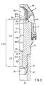
- FIG. 3 shows a section of a further selected, particularly advantageous exemplary embodiment.
- the fuel distributor 30 consists of a dimensionally stable Material, preferably metal, and the pressure line 32nd and the return line 34 are in the fuel rail 30 intended.
- the pressure control valve 2 with the Lower housing part 4a and the connecting piece 10 in the Fuel distributor 30 inserted and as already described sealed.
- FIG. 3 shows a Embodiment in which the return line 34 in a elastic hose 42 runs.
- the hose line 42 is in FIG. 3 for better clarity shown in dashed lines.
- an extension 44 on the connecting piece 10 intended In the illustrated in Figure 3 Embodiment closes, from the direction of Valve seat 16 considered, to the second section 22 further section 46.
- the diameter of the further section 46 is much larger than the diameter D22 of the second section 22.
- the diameter of the further section 46 is so large that in the area of the further section 46 practically no throttling of the flow rate takes place.
- the transition can also have a perpendicular to the connection opening 20th level.
- the ball 8a of the closing body 8 relative to the outer diameter of the connecting piece 10 somewhat dimensioned smaller.
- the sealing gap 40 with the sealing gap length L40 starts at the outside diameter D16 and ends at the diameter D21.
- the chamfer 21a shown in FIG. 2 is dispensed with.
- 3 has the first section 21 between the end face 10a and the stage 21b throughout the effective cylindrical Diameter D21.
- At level 21b comes next to the diameter D21 the 0.1 mm smaller Diameter D21 ''.
- the Closing body 8 the ball resting on the connecting piece 10 8a.
- the ball 8a for example also one with the closing body 8 directly or connected via a ball mounted in the holding element 8b Plate can be provided, which is in the closed Condition on the valve seat 16 of the connecting piece 10 is supported.
- Another embodiment of the pressure control valve 2 can For example, look like that with the ball 8a the surface 8f is dispensed with.
- this modified embodiment has the support on the connecting piece 10 Ball 8a no flattening and that's what Valve seat 16 on the connecting piece 10 adapted accordingly. That is, the valve seat 16 on the connector 10 is, for example conical or dome-shaped.
Landscapes
- Engineering & Computer Science (AREA)
- General Engineering & Computer Science (AREA)
- Mechanical Engineering (AREA)
- Chemical & Material Sciences (AREA)
- Combustion & Propulsion (AREA)
- Fuel-Injection Apparatus (AREA)
- Safety Valves (AREA)
- Details Of Valves (AREA)
- Lift Valve (AREA)
- Control Of Fluid Pressure (AREA)
Claims (18)
- Soupape de régulation de pression, en particulier pour installations alimentant en carburant des moteurs à combustion interne, comportant :caractérisée en ce queun boítier de soupape dans lequel est tendue une membrane divisant le boítier en une chambre de carburant et une chambre de soupape,une tubulure de raccordement (10) présentant un passage de raccordement (20) et comportant, entourant ce passage, un siège de soupape, ainsi qu'un corps de fermeture (8) relié à la membrane et soumis, en direction du siège de soupape, à une force de fermeture,entre le corps de fermeture et la tubulure de raccordement, une fente périphérique d'étanchéité (40) qui sépare, en fonction de la pression, la chambre de carburant et le passage de raccordement (20) qui, en partant du siège de soupape (16) présente, une première partie (21) avec une surface de section (A21) supérieure et une seconde partie (22) avec une surface de section (A22) inférieure,
la surface inférieure (A22) est, vis à vis de la surface supérieure de section (A21) dans un rapport compris entre 1 à 1,65 et 1 à 3,33, la seconde partie (22) ayant une longueur (L22) qui est jusqu'à 5,83 fois plus grande qu'une longueur efficace (L40) de la fente d'étanchéité (40). - Soupape de régulation selon la revendication 1,
caractérisée en ce que
la première partie (21) a un diamètre (D21) qui est de 1,29 à 1,82 fois plus grand que le diamètre (D22) de la seconde partie (22). - Soupape de régulation selon la revendication 2,
caractérisée en ce que
le diamètre (D21) de la première partie (21) est compris entre 2,7 et 3,1 mm. - Soupape de régulation selon la revendication 2,
caractérisée en ce que
le diamètre (D21) de la première partie (21) est compris entre 2,8 et 3,0 mm. - Soupape de régulation selon la revendication 2,
caractérisée en ce que
le diamètre (D21) de la première partie (21) est de 2,9 mm environ. - Soupape de régulation selon l'une quelconque des revendications 2 à 5,
caractérisée en ce que
le diamètre (D22) de la seconde partie (22) est compris entre 1,7 et 2,1 mm. - Soupape de régulation selon l'une quelconque des revendications 2 à 5,
caractérisée en ce que
le diamètre (D22) de la seconde partie (22) est compris entre 1,8 et 2,0 mm. - Soupape de régulation selon l'une quelconque des revendications 2 à 5,
caractérisée en ce que
le diamètre (D22) de la seconde partie (22) est d'environ 1,9 mm. - Soupape de régulation selon l'une quelconque des revendications précédentes,
caractérisée en ce que
la longueur (L40) de la fente d'étanchéité (40) est de 1,2 mm au moins. - Soupape de régulation selon l'une quelconque des revendications 1 à 8,
caractérisée en ce que
la longueur (L40) de la fente d'étanchéité (40) est comprise entre 1,2 et 1,6 mm. - Soupape de régulation selon l'une quelconque des revendications 1 à 8,
caractérisée en ce que
la longueur (L40) de la fente d'étanchéité (40) est de 1,35 mm. - Soupape de régulation selon l'une quelconque des revendications précédentes,
caractérisée en ce que
la longueur (L22) de la seconde partie (22) est comprise entre 4,0 et 7,0 mm. - Soupape de régulation selon l'une quelconque des revendications 1 à 11,
caractérisée en ce que
la longueur (L22) de la seconde partie (22) est comprise entre 4,5 et 6,0 mm. - Soupape de régulation selon l'une quelconque des revendications 1 à 11,
caractérisée en ce que
la longueur (L22) de la seconde partie (22) est de 5,0 à 5,5 mm. - Soupape de régulation selon l'une quelconque des revendications précédentes,
caractérisée en ce que
la première partie (21) et la seconde partie (22) présentent ensemble une longueur totale (L20) qui est de 2 à 5,5 fois celle de la seconde partie (22). - Soupape de régulation selon la revendication 15,
caractérisée en ce que
la longueur totale (L20) de l'ensemble de la première partie (21) et de la seconde partie (22) est comprise entre 14 et 22 mm. - Soupape de régulation selon la revendication 15,
caractérisée en ce que
la longueur totale (L20) de l'ensemble de la première partie (21) et de la seconde partie (22) est comprise entre 15 et 18 mm. - Soupape de régulation selon la revendication 17,
caractérisée en ce que
la longueur totale (L20) de l'ensemble de la première partie (21) et de la seconde partie (22) est de 16 à 17 mm.
Applications Claiming Priority (3)
| Application Number | Priority Date | Filing Date | Title |
|---|---|---|---|
| DE19548167A DE19548167A1 (de) | 1995-12-22 | 1995-12-22 | Druckregelventil |
| DE19548167 | 1995-12-22 | ||
| PCT/DE1996/001394 WO1997023741A1 (fr) | 1995-12-22 | 1996-07-26 | Soupape de regulation de la pression |
Publications (2)
| Publication Number | Publication Date |
|---|---|
| EP0830536A1 EP0830536A1 (fr) | 1998-03-25 |
| EP0830536B1 true EP0830536B1 (fr) | 2001-10-31 |
Family
ID=7781031
Family Applications (1)
| Application Number | Title | Priority Date | Filing Date |
|---|---|---|---|
| EP96924775A Expired - Lifetime EP0830536B1 (fr) | 1995-12-22 | 1996-07-26 | Soupape de regulation de la pression |
Country Status (8)
| Country | Link |
|---|---|
| US (1) | US5967177A (fr) |
| EP (1) | EP0830536B1 (fr) |
| JP (1) | JPH11501388A (fr) |
| KR (1) | KR100413938B1 (fr) |
| CZ (1) | CZ291437B6 (fr) |
| DE (2) | DE19548167A1 (fr) |
| ES (1) | ES2166897T3 (fr) |
| WO (1) | WO1997023741A1 (fr) |
Cited By (1)
| Publication number | Priority date | Publication date | Assignee | Title |
|---|---|---|---|---|
| CN104847948A (zh) * | 2015-05-07 | 2015-08-19 | 北京航空航天大学 | 一种高精度自动控制减压器 |
Families Citing this family (12)
| Publication number | Priority date | Publication date | Assignee | Title |
|---|---|---|---|---|
| US6135092A (en) * | 1997-10-29 | 2000-10-24 | General Motors Corporation | Fuel injection system |
| KR100464288B1 (ko) | 2001-01-16 | 2005-01-03 | 가부시키가이샤 덴소 | 연료압력조정밸브 |
| KR100852868B1 (ko) * | 2002-04-23 | 2008-08-20 | 로베르트 보쉬 게엠베하 | 압력 조절기 |
| EP1412635B1 (fr) * | 2002-06-06 | 2005-08-17 | Siemens VDO Automotive Corporation | Regulateur possedant des diffuseurs d'ecoulement multiples |
| US6886590B2 (en) * | 2002-09-20 | 2005-05-03 | Siemens Vdo Automative Corporation | Seal assembly for fuel pressure regulator |
| DE102007016134A1 (de) | 2006-04-25 | 2007-11-08 | Robert Bosch Gmbh | Kraftstoff-Hochdruckpumpe |
| JP4941324B2 (ja) * | 2008-01-22 | 2012-05-30 | 三菱電機株式会社 | 燃料圧力調整器およびそれを用いた燃料供給装置 |
| US8302622B2 (en) * | 2010-02-24 | 2012-11-06 | Continental Automotive Systems Us, Inc. | Unbalanced inlet fuel tube for a fuel pressure regulator |
| US20120048237A1 (en) * | 2010-08-31 | 2012-03-01 | Gm Global Technology Operations, Inc. | Fuel pressure regulator |
| JP5912993B2 (ja) * | 2012-08-20 | 2016-04-27 | 愛三工業株式会社 | 燃料圧力制御弁 |
| CN106268517A (zh) * | 2016-08-12 | 2017-01-04 | 胡海潮 | 用于恩替卡韦制备的调压反应釜 |
| JP6677146B2 (ja) * | 2016-11-24 | 2020-04-08 | 株式会社Soken | 弁構造体 |
Family Cites Families (8)
| Publication number | Priority date | Publication date | Assignee | Title |
|---|---|---|---|---|
| JPS61149567A (ja) * | 1984-12-21 | 1986-07-08 | Nippon Denso Co Ltd | 圧力制御弁 |
| US4625695A (en) * | 1985-03-28 | 1986-12-02 | Walbro Corporation | Fuel pressure regulator |
| US4646700A (en) * | 1985-04-17 | 1987-03-03 | Walbro Corporation | Pressure regulator for liquid fuel system |
| US4936342A (en) * | 1988-01-27 | 1990-06-26 | Mitsuba Electric Manufacturing Co., Ltd. | Fuel pressure control valve device |
| SE465533B (sv) * | 1990-02-19 | 1991-09-23 | Saab Automobile | Tyst backventil foer pulserande floede |
| US5076320A (en) * | 1990-10-19 | 1991-12-31 | Siemens Automotive L.P. | Fuel rail mounted fuel pressure regulator |
| JP2985471B2 (ja) * | 1992-02-04 | 1999-11-29 | 株式会社デンソー | 燃料圧力調整装置 |
| US5220941A (en) * | 1992-06-02 | 1993-06-22 | Walbro Corporation | Fuel pressure regulator |
-
1995
- 1995-12-22 DE DE19548167A patent/DE19548167A1/de not_active Withdrawn
-
1996
- 1996-07-26 EP EP96924775A patent/EP0830536B1/fr not_active Expired - Lifetime
- 1996-07-26 ES ES96924775T patent/ES2166897T3/es not_active Expired - Lifetime
- 1996-07-26 KR KR1019970705821A patent/KR100413938B1/ko not_active Expired - Lifetime
- 1996-07-26 DE DE59608077T patent/DE59608077D1/de not_active Expired - Lifetime
- 1996-07-26 WO PCT/DE1996/001394 patent/WO1997023741A1/fr not_active Ceased
- 1996-07-26 CZ CZ19972606A patent/CZ291437B6/cs not_active IP Right Cessation
- 1996-07-26 US US08/894,624 patent/US5967177A/en not_active Expired - Lifetime
- 1996-07-26 JP JP9523192A patent/JPH11501388A/ja active Pending
Cited By (1)
| Publication number | Priority date | Publication date | Assignee | Title |
|---|---|---|---|---|
| CN104847948A (zh) * | 2015-05-07 | 2015-08-19 | 北京航空航天大学 | 一种高精度自动控制减压器 |
Also Published As
| Publication number | Publication date |
|---|---|
| CZ291437B6 (cs) | 2003-03-12 |
| JPH11501388A (ja) | 1999-02-02 |
| DE59608077D1 (de) | 2001-12-06 |
| US5967177A (en) | 1999-10-19 |
| KR100413938B1 (ko) | 2004-04-28 |
| ES2166897T3 (es) | 2002-05-01 |
| CZ9702606A3 (cs) | 2001-01-17 |
| KR19980702422A (ko) | 1998-07-15 |
| DE19548167A1 (de) | 1997-06-26 |
| WO1997023741A1 (fr) | 1997-07-03 |
| EP0830536A1 (fr) | 1998-03-25 |
Similar Documents
| Publication | Publication Date | Title |
|---|---|---|
| EP0961027B1 (fr) | Soupape de régulation de pression | |
| EP0830536B1 (fr) | Soupape de regulation de la pression | |
| DE69112386T2 (de) | Geräuschloses rückschlagventil für pulsierende strömungen. | |
| DE3307554A1 (de) | Elektrisch regelbares druckreduzierventil | |
| EP1689999A1 (fr) | Dispositif d'injection de carburant destine a un moteur a combustion interne, notamment a un moteur a combustion interne a injection directe, et procede de fabrication | |
| DE2710216A1 (de) | Kraftstoffeinspritzduese | |
| DE102004012281A1 (de) | Einfacher Aufbau eines Kraftstoffdruckreglers, der zum Minimieren eines Druckverlustes ausgelegt ist | |
| DE19962960A1 (de) | Druckregelventil und Verfahren zum Herstellen eines Druckregelventils | |
| DE69203156T2 (de) | Selbsttätiges Entlüftungsventil. | |
| DE3718784A1 (de) | Elektromagnetische kraftstoffeinspritzduese | |
| DE10152173A1 (de) | Magnetventil zur Steuerung eines Einspritzventils | |
| DE8632002U1 (de) | Kraftstoffeinspritzventil | |
| DE69107405T2 (de) | Hochdruck-Dichtungssystem für das Steuerventil eines elektromagnetischen Brennstoffeinspritzventils für Verbrennungsmotoren. | |
| DE3151020C2 (fr) | ||
| DE102014206964A1 (de) | Kompakter Kraftstoffdruckregler | |
| DE10024854A1 (de) | Steuerelemente für Hochdruckhydraulikanlagen | |
| DE2612122A1 (de) | Steuergeraet | |
| DE19755303A1 (de) | Kraftstoffversorgungssystem | |
| DE102018208361A1 (de) | Verfahren zum Betreiben eines Kraftstoffinjektors, Kraftstoffinjektor | |
| EP1035312A2 (fr) | Corps de papillon pour commander la puissance d'un moteur à combustion | |
| EP1574701A1 (fr) | Injecteur de common rail | |
| DE2349631C2 (de) | Kraftstoffeinspritzanlage | |
| DE29612018U1 (de) | Abgasrückführungsventil | |
| EP1431576B1 (fr) | Pompe à piston | |
| DE69900704T2 (de) | Dosiervorrichtung |
Legal Events
| Date | Code | Title | Description |
|---|---|---|---|
| PUAI | Public reference made under article 153(3) epc to a published international application that has entered the european phase |
Free format text: ORIGINAL CODE: 0009012 |
|
| 17P | Request for examination filed |
Effective date: 19980105 |
|
| AK | Designated contracting states |
Kind code of ref document: A1 Designated state(s): DE ES FR GB IT |
|
| 17Q | First examination report despatched |
Effective date: 19991130 |
|
| GRAG | Despatch of communication of intention to grant |
Free format text: ORIGINAL CODE: EPIDOS AGRA |
|
| GRAG | Despatch of communication of intention to grant |
Free format text: ORIGINAL CODE: EPIDOS AGRA |
|
| GRAH | Despatch of communication of intention to grant a patent |
Free format text: ORIGINAL CODE: EPIDOS IGRA |
|
| GRAH | Despatch of communication of intention to grant a patent |
Free format text: ORIGINAL CODE: EPIDOS IGRA |
|
| GRAA | (expected) grant |
Free format text: ORIGINAL CODE: 0009210 |
|
| AK | Designated contracting states |
Kind code of ref document: B1 Designated state(s): DE ES FR GB IT |
|
| REF | Corresponds to: |
Ref document number: 59608077 Country of ref document: DE Date of ref document: 20011206 |
|
| REG | Reference to a national code |
Ref country code: GB Ref legal event code: IF02 |
|
| GBT | Gb: translation of ep patent filed (gb section 77(6)(a)/1977) |
Effective date: 20020121 |
|
| ET | Fr: translation filed | ||
| REG | Reference to a national code |
Ref country code: ES Ref legal event code: FG2A Ref document number: 2166897 Country of ref document: ES Kind code of ref document: T3 |
|
| PLBE | No opposition filed within time limit |
Free format text: ORIGINAL CODE: 0009261 |
|
| STAA | Information on the status of an ep patent application or granted ep patent |
Free format text: STATUS: NO OPPOSITION FILED WITHIN TIME LIMIT |
|
| 26N | No opposition filed | ||
| PGFP | Annual fee paid to national office [announced via postgrant information from national office to epo] |
Ref country code: ES Payment date: 20110728 Year of fee payment: 16 |
|
| REG | Reference to a national code |
Ref country code: ES Ref legal event code: FD2A Effective date: 20131021 |
|
| PG25 | Lapsed in a contracting state [announced via postgrant information from national office to epo] |
Ref country code: ES Free format text: LAPSE BECAUSE OF NON-PAYMENT OF DUE FEES Effective date: 20120727 |
|
| REG | Reference to a national code |
Ref country code: FR Ref legal event code: PLFP Year of fee payment: 20 |
|
| PGFP | Annual fee paid to national office [announced via postgrant information from national office to epo] |
Ref country code: GB Payment date: 20150724 Year of fee payment: 20 |
|
| PGFP | Annual fee paid to national office [announced via postgrant information from national office to epo] |
Ref country code: FR Payment date: 20150730 Year of fee payment: 20 |
|
| PGFP | Annual fee paid to national office [announced via postgrant information from national office to epo] |
Ref country code: IT Payment date: 20150728 Year of fee payment: 20 |
|
| PGFP | Annual fee paid to national office [announced via postgrant information from national office to epo] |
Ref country code: DE Payment date: 20150925 Year of fee payment: 20 |
|
| REG | Reference to a national code |
Ref country code: DE Ref legal event code: R071 Ref document number: 59608077 Country of ref document: DE |
|
| REG | Reference to a national code |
Ref country code: GB Ref legal event code: PE20 Expiry date: 20160725 |
|
| PG25 | Lapsed in a contracting state [announced via postgrant information from national office to epo] |
Ref country code: GB Free format text: LAPSE BECAUSE OF EXPIRATION OF PROTECTION Effective date: 20160725 |