EP0830559B1 - Dispositif de vision reflexe pour la vision de jour et de nuit - Google Patents
Dispositif de vision reflexe pour la vision de jour et de nuit Download PDFInfo
- Publication number
- EP0830559B1 EP0830559B1 EP96924255A EP96924255A EP0830559B1 EP 0830559 B1 EP0830559 B1 EP 0830559B1 EP 96924255 A EP96924255 A EP 96924255A EP 96924255 A EP96924255 A EP 96924255A EP 0830559 B1 EP0830559 B1 EP 0830559B1
- Authority
- EP
- European Patent Office
- Prior art keywords
- light
- fiber optic
- source
- sighting device
- core portion
- Prior art date
- Legal status (The legal status is an assumption and is not a legal conclusion. Google has not performed a legal analysis and makes no representation as to the accuracy of the status listed.)
- Expired - Lifetime
Links
- 230000011514 reflex Effects 0.000 title description 13
- 239000000835 fiber Substances 0.000 claims description 128
- 238000005286 illumination Methods 0.000 claims description 59
- 239000013307 optical fiber Substances 0.000 claims description 46
- 239000000463 material Substances 0.000 claims description 29
- 238000005253 cladding Methods 0.000 claims description 18
- 230000008878 coupling Effects 0.000 claims description 10
- 238000010168 coupling process Methods 0.000 claims description 10
- 238000005859 coupling reaction Methods 0.000 claims description 10
- 230000004044 response Effects 0.000 claims description 8
- WYTGDNHDOZPMIW-RCBQFDQVSA-N alstonine Natural products C1=CC2=C3C=CC=CC3=NC2=C2N1C[C@H]1[C@H](C)OC=C(C(=O)OC)[C@H]1C2 WYTGDNHDOZPMIW-RCBQFDQVSA-N 0.000 claims description 6
- 230000000694 effects Effects 0.000 claims description 3
- 239000011162 core material Substances 0.000 description 44
- 230000005540 biological transmission Effects 0.000 description 43
- YZCKVEUIGOORGS-NJFSPNSNSA-N Tritium Chemical compound [3H] YZCKVEUIGOORGS-NJFSPNSNSA-N 0.000 description 17
- 229910052722 tritium Inorganic materials 0.000 description 17
- 238000010276 construction Methods 0.000 description 12
- 239000011248 coating agent Substances 0.000 description 11
- 238000000576 coating method Methods 0.000 description 11
- 230000003287 optical effect Effects 0.000 description 11
- 229910003460 diamond Inorganic materials 0.000 description 5
- 239000010432 diamond Substances 0.000 description 5
- 230000008901 benefit Effects 0.000 description 4
- 239000004793 Polystyrene Substances 0.000 description 3
- 230000006870 function Effects 0.000 description 3
- 238000000034 method Methods 0.000 description 3
- 230000002093 peripheral effect Effects 0.000 description 3
- 239000004033 plastic Substances 0.000 description 3
- 229920003023 plastic Polymers 0.000 description 3
- 229920002223 polystyrene Polymers 0.000 description 3
- 241000284156 Clerodendrum quadriloculare Species 0.000 description 2
- 229920004142 LEXAN™ Polymers 0.000 description 2
- 239000004418 Lexan Substances 0.000 description 2
- NIXOWILDQLNWCW-UHFFFAOYSA-N acrylic acid group Chemical group C(C=C)(=O)O NIXOWILDQLNWCW-UHFFFAOYSA-N 0.000 description 2
- 230000008859 change Effects 0.000 description 2
- 238000010586 diagram Methods 0.000 description 2
- 230000004438 eyesight Effects 0.000 description 2
- 239000011521 glass Substances 0.000 description 2
- 230000013011 mating Effects 0.000 description 2
- 239000000382 optic material Substances 0.000 description 2
- 239000004417 polycarbonate Substances 0.000 description 2
- 229920000515 polycarbonate Polymers 0.000 description 2
- 230000008569 process Effects 0.000 description 2
- 230000001681 protective effect Effects 0.000 description 2
- 230000000007 visual effect Effects 0.000 description 2
- 229920000049 Carbon (fiber) Polymers 0.000 description 1
- 229920004738 ULTEM® Polymers 0.000 description 1
- 235000010724 Wisteria floribunda Nutrition 0.000 description 1
- 230000009471 action Effects 0.000 description 1
- XAGFODPZIPBFFR-UHFFFAOYSA-N aluminium Chemical compound [Al] XAGFODPZIPBFFR-UHFFFAOYSA-N 0.000 description 1
- 229910052782 aluminium Inorganic materials 0.000 description 1
- 230000003321 amplification Effects 0.000 description 1
- 238000005452 bending Methods 0.000 description 1
- 230000000903 blocking effect Effects 0.000 description 1
- 239000004917 carbon fiber Substances 0.000 description 1
- 230000007423 decrease Effects 0.000 description 1
- 230000009977 dual effect Effects 0.000 description 1
- 230000005284 excitation Effects 0.000 description 1
- 210000000887 face Anatomy 0.000 description 1
- 239000002657 fibrous material Substances 0.000 description 1
- 239000005357 flat glass Substances 0.000 description 1
- 239000004811 fluoropolymer Substances 0.000 description 1
- 229920002313 fluoropolymer Polymers 0.000 description 1
- 210000003128 head Anatomy 0.000 description 1
- 230000006872 improvement Effects 0.000 description 1
- 230000004301 light adaptation Effects 0.000 description 1
- VNWKTOKETHGBQD-UHFFFAOYSA-N methane Chemical compound C VNWKTOKETHGBQD-UHFFFAOYSA-N 0.000 description 1
- 230000004048 modification Effects 0.000 description 1
- 238000012986 modification Methods 0.000 description 1
- 230000004297 night vision Effects 0.000 description 1
- 238000003199 nucleic acid amplification method Methods 0.000 description 1
- 230000008447 perception Effects 0.000 description 1
- 229920001296 polysiloxane Polymers 0.000 description 1
- 230000036421 sense of balance Effects 0.000 description 1
- 230000035945 sensitivity Effects 0.000 description 1
- 239000012815 thermoplastic material Substances 0.000 description 1
- 238000002834 transmittance Methods 0.000 description 1
- 230000008016 vaporization Effects 0.000 description 1
- 238000001429 visible spectrum Methods 0.000 description 1
- 238000005406 washing Methods 0.000 description 1
- XLYOFNOQVPJJNP-UHFFFAOYSA-N water Substances O XLYOFNOQVPJJNP-UHFFFAOYSA-N 0.000 description 1
Images




Classifications
-
- F—MECHANICAL ENGINEERING; LIGHTING; HEATING; WEAPONS; BLASTING
- F41—WEAPONS
- F41G—WEAPON SIGHTS; AIMING
- F41G1/00—Sighting devices
- F41G1/32—Night sights, e.g. luminescent
- F41G1/34—Night sights, e.g. luminescent combined with light source, e.g. spot light
- F41G1/345—Night sights, e.g. luminescent combined with light source, e.g. spot light for illuminating the sights
-
- G—PHYSICS
- G02—OPTICS
- G02B—OPTICAL ELEMENTS, SYSTEMS OR APPARATUS
- G02B23/00—Telescopes, e.g. binoculars; Periscopes; Instruments for viewing the inside of hollow bodies; Viewfinders; Optical aiming or sighting devices
- G02B23/02—Telescopes, e.g. binoculars; Periscopes; Instruments for viewing the inside of hollow bodies; Viewfinders; Optical aiming or sighting devices involving prisms or mirrors
- G02B23/10—Telescopes, e.g. binoculars; Periscopes; Instruments for viewing the inside of hollow bodies; Viewfinders; Optical aiming or sighting devices involving prisms or mirrors reflecting into the field of view additional indications, e.g. from collimator
- G02B23/105—Sighting devices with light source and collimating reflector
Definitions
- the present invention relates to an optical sighting device for day or night sighting and more particularly to a reflex sighting device.
- Reflex sights are well-known and have taken a variety of forms, such as in gun sights and camera view finders. In substantially all forms, however, some type of reticle pattern is utilized to mark the area or object of interest. Light or the illuminated image from this reticle pattern is reflected from a semi-transparent, semi-reflective mirror or lens surface through which the object or field is viewed. The curvature of the semi-reflecting surface is such as to direct the reflected rays of the reticle image to converge approximately at the same viewing point of the operator as the transmitted rays of the object or field being sighted and thereby to make the reticle pattern appear at infinity and superimposed upon the object or field and at approximately the same distance.
- a reflex sight comprising a reticle and a dichroic beam combining mirror for combining rays of light from the reticle with rays of light from an object or field.
- the dichroic mirror has high reflectance in one part of the visible spectrum and high transmittance in the other parts to provide the dual image to the viewer or operator.
- Temporarily closing one eye during aiming interrupts the visual signal from one eye and can begin to change the state of light adaptation and point in space upon which the open eye was fixed.
- a dichroic mirror is utilized in reflex sights. Such a dichroic mirror reflects nearly all light above one wavelength and transmits nearly all light below that wavelength. If a red or orange dot is used as the aiming mark or reticle, the mirror will reflect red/orange light and transmit yellow, green and blue light. Thus the dichroic mirror changes the color of a target scene. If the target is viewed with one eye only, the loss of the red color from the target area will be observed. When the other eye is opened, the missing color will be put back into the target scene perceived by the viewer or operator.
- a reflex sight which is non-magnifying, is particularly advantageous for aiming with both eyes open because it does not interrupt binocular vision at all, i.e. such as with telescopic or magnifying optical sights.
- a reflex sight which is non-magnifying, is particularly advantageous for aiming with both eyes open because it does not interrupt binocular vision at all, i.e. such as with telescopic or magnifying optical sights.
- the aiming mark contrast can be inconsistent. For example if the aiming mark or reticle is extremely bright it may be most suitable for aiming at brightly lit target scenes but could be too bright for dimly lit target scenes and, of course, the reverse is also true.
- aiming at a dark object in heavy shade can be difficult or inaccurate without a suitable means to improve contrast of the aiming mark or reticle.
- numerous ways have been devised whereby the aiming mark brightness can be varied to improve contrast with the target scene, i.e. battery powered LEDs, electric lights, etc. which are controlled manually or electronically
- a unique construction is utilized to vary the reticle brightness in proportion to the target. scene brightness in day and night sighting while providing an illumination intensity for day sighting which provides a desired contrast comparable to that of an artificial light source for night sighting.
- Another objective is to provide a design in which compensating variations in reticle brightness occur naturally without the need for manual adjustment such as with a brightness knob or electronic control.
- a unique fiber optic structure is utilized in which a fiber optic light collector receives ambient light focused transversely or radially inwardly over a selected length of fiber whereby a desired magnitude of light energy can be gathered from ambient light to provide illumination to the reticle.
- a radio-luminescent source is used in combination with the fiber optic collector resulting in a combined illumination whereby a desired level of illumination can be provided to the reticle over the full range of brightness during day and night sighting.
- a source of light as defined in claim 1 and a sighting device as defined in claims 3, 7, 21 and 34.
- the reflex sighting device of the present invention utilizes a light collector assembly having a fiber optic structure designed to gather a significant, predetermined quantity of the available ambient light focused thereon.
- the light collected by the fiber optic structure is then transmitted to a reticle defining structure which is located to transmit a reticle image or pattern onto a dichroic lens or mirror.
- further illumination of the reticle structure is provided by a source of artificial light such as a tritium lamp.
- the illumination from the light collector assembly is provided primarily for day sighting while the illumination from the tritium lamp is primarily for night sighting. Both sources of illumination are applied to the reticle defining structure at the same time.
- the level of illumination of the reticle pattern be a function of the level of illumination of the object or scene being viewed through the sight the magnitude of illumination from the tritium lamp will be considerably less than that from the collector assembly.
- the level of reticle illumination will be determined primarily by the collector assembly while night illumination will be primarily determined by the tritium lamp.
- the magnitude of illumination of the tritium lamp can be further reduced by imposing a movable mask or shield between the lamp and the fiber to permit selective attenuation or blockage of the illumination from the lamp.
- the level of illumination from the collector assembly with its fiber optic structure will vary naturally in accordance with the daylight illumination of the object or scene being viewed and in this regard will be balanced with a known level of illumination provided by the artificial light source.
- the amount of light collected can be selected to provide the desired degree of contrast with the scene being viewed over the full range of luminance of the scene.
- features of the present invention can be used to collect ambient light from different directions such as the brighter overhead sky.
- the reflex sighting device of the present invention is depicted as a gun sight 10 adapted to be mounted on a rifle 12 via a mounting bracket 13.
- the gun sight or sighting device 10 includes a generally elongated housing 14 and a base 16.
- a dichroic mirror or lens 18 having a circular outer contour is mounted in a mating circular through bore 20 located in a raised front portion 22 of the housing 14.
- the dichroic mirror 18 is held in one axial direction by a reduced diameter, coaxial shoulder 24.
- a light collector assembly 26 is adapted to be located in a cavity 28 at the forward end of the housing 14 and comprises a fiber optic structure 30, a retainer 32 for supporting the structure 30 and a light collecting lens 34.
- the fiber optic structure 30 includes a fiber optic light collector section 31 and a separate fiber optic transmission line 36 which is connected therewith to an end fiber line 33 by way of a fiber optic coupling 35 of a known construction (see Figures 6, 11 and 12).
- the use of a transmission line 36 separate from the collector section 31 serves a purpose to be described.
- the ambient light captured by the collector section 31 is transmitted through the housing 14 by the fiber optic transmission line 36.
- the fiber optic transmission line 36 extends substantially through the housing 14 to its rearward end.
- the housing 14 has a longitudinal, generally arcuate, concave slot 37 in its upper surface which extends from an enlarged contour at the through bore 20 and the dichroic mirror 18 and tapers to a reduced size at an opening 38 proximate the rearward end of the housing 14.
- the slot opening 38 communicates with the inside of the housing 14.
- An inner wall 40 is located on the inside of the housing 14 in a location spaced rearwardly of the slot opening 38 (see Figures 3 and 4).
- the free end of the transmission line 36 is adapted to be supported in a bore 42 in the inner wall 40 in confrontation with the slot opening 38 (see Figures 3 and 13).
- a supporting ring 44 is located about the end of the transmission line 36 and is adapted to secure that end in the bore 42 (see Figure 13).
- the exposed end face 46 of the transmission line 36 is located to be facing the dichroic mirror 18 through the slot opening 38 to transmit the light emanating therefrom to the dichroic mirror 18 along the line A (see Figures 4 and 11).
- the fiber optic collector section 31 and the associated transmission line 36 are constructed of optical fibers having a core portion 50, 50' and an outer casing 52, 52'.
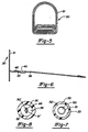
- the reticle pattern is defined by the shape of the core portion 50' at the exposed end face 46 (see Figure 11) of the transmission line 36 which can be a circular dot as shown in Figure 7.
- the dichroic mirror 18 is arcuately contoured in a manner well known in the art to reflect the reticle pattern back to the eye of the operator along the line B which is essentially in coincidence with the sight line of the operator.
- the fiber of the transmission line 36 including the casing 52' and core portion 50' are provided to be of a slightly smaller diameter than casing 52 and core portion 50 of the collector section 31 and hence of the fiber line 33.
- This facilitates alignment of the slightly smaller core portion 50' of the transmission line 36 with the core portion 50 of the end fiber line 33 whereby the light transmitted can be optimized.
- This also facilitates use of a diamond shaped core portion 50' on the transmission line 36 to define the dot or reticle pattern at the end face 46 with the collimator section 31 having a fiber of a simpler construction with a slightly larger circular core portion 50.
- the difference in diameters facilitates the effective transmission of collected light from the larger circular core portion 50 to the smaller diamond shaped core portion 50'.
- the light collector section 31 will provide illumination to the exposed end face 46 of the fiber optic line 36 via the fiber line 33 whereby an illuminated reticle pattern will be provided to the viewer or operator.
- the intensity of illumination or brightness of the light emitted from the end face 46 and hence of the reflected reticle pattern will vary as a function of the level of intensity of the ambient light.
- a radio-luminescent source or tritium lamp 48 is optically connected to the fiber optic transmission line 36 via the fiber line 33 within the housing 14 at a location proximate to the coupling 35 (see Figures 6, 11 and 12).
- the tritium lamp 48 will provide a level of illumination to the end face 46 significantly lower than the maximum intensity provided by the fiber optic collector section 31 at peak daylight sighting.
- the tritium lamp 48 was of the type T-4734 manufactured and sold by M B Microtec.
- the fiber optic collector section 31 is constructed of an optical fiber preferably made with the core portion 50 constructed of a pigmented fluorescent polystyrene material having a refractive index of around 1.592 with an outer cladding 51 of a clear acrylic material having a refractive index of around 1.492.
- the same pigmented fluorescent polystyrene core portion 50 is first covered with a fluoropolymer cladding 51 with a refractive index of around 1.408.
- the core portion 50 with its cladding 51 is then surrounded with the outer casing 52 of clear polystyrene material.
- optical fibers of different constructions could be utilized including core portions, such as portion 50, of different light activated material.
- the optical fiber of the transmission line 36 is constructed similarly to that as shown in Figure 7 and as described above with reference to the collector section 31 except that the core portion 50 is constructed of a non pigmented clear acrylic material having a refractive index of around 1.492.
- the core portion 50 of the transmission line 36 defines the shape of the reticle pattern which as shown will be a circular dot ( Figure 7) or a diamond dot ( Figure 8).
- the ambient light impinging on the fiber optic collector section 31 will excite the fluorescent material to generate light for illuminating the reticle pattern.
- the diameter of the core portion 50 of the optic fiber was around .0057 inches (.144 mm) while the major diameter of the optic fiber was around .0255 inches (.65 mm).
- a suitable fiber material can be generally of the type manufactured and sold by Opectron under the designation F204.
- the optical fiber of the transmission line 36 will have slightly smaller dimensions, i.e. around 10% less than that of the collector section 31 and hence of the fiber line 33.
- the fiber optic transmission line 36 is not exposed to ambient light as is the collector section 31. Instead the line 36 passes in the internal shadow of the main housing 14. If the core portion 50' of the transmission line 36 were constructed of a pigmented fluorescent material as is the optical fiber of the collector section 31, then the light traveling through the fiber optic line 36 in the housing 14 could experience some loss in intensity resulting from such fluorescent treatment. Thus in the embodiment shown in Figure 11, the separate transmission line 36 is constructed with a clear core portion 50' whereby such losses are avoided.
- the construction described above serves to efficiently provide a reticle pattern of a desired size for the chosen focal length of the dichroic mirror or lens 18.
- the focal length of the dichroic mirror or lens 18 was around 3.00 inches (76.2 mm).
- the fiber optic collector section 31 is arranged in a generally serpentine configuration defined by a series of coils of increasing size.
- the desired shape of the collector section 31 can be preformed by known processes. For example a selected length of generally straight fiber optic material can be formed into the desired serpentine shape by immersing it in water at around 212°F or 100°C and then, while in a plastic state, bending it to the desired shape on a suitable mold. When cooled the desired serpentine shape will be maintained. However since the details of that process do not constitute a part of the present invention such details have been omitted for purposes of simplicity.
- the fiber optic collector section 31 in its preferred serpentine shape can then be located in a similarly shaped groove 54 in the outer face of the retainer 32.
- the retainer 32 has an outer contour generally matching that of the cavity 28 and is adapted to be received therein and has an annular shoulder 55 adapted to engage the outer circular edge of the dichroic mirror 18 to support the mirror 18 in the cavity 28 against the shoulder 24.
- the ambient light is focused radially inwardly or transversely into the coils of the collector section 31 by the light collecting lens 34.
- the collecting lens 34 has a peripheral contour generally matching that of the retainer 32 and hence of the cavity 28 and is adapted to be located therein.
- the collector assembly 26 then can be fixed in the cavity 28 by a pair of screws, such as screw 57, extending through aligned mounting openings in the retainer 32 and collecting lens 34 and into threaded bores 56 in the end wall of the cavity 28.
- the collecting lens 34 has a generally flat or planar inner surface 58 adapted to engage the outer surface of the coils of the collector section 31 when located in the groove 54 in the retainer 32.
- the axially outer surface 61 of the collecting lens 34 is formed with a lens track 62 having a serpentine configuration matching that of the fiber optic collector section 31 and groove 54 in retainer 32.
- the lens track 62 has as an arcuate shape defining a convex lens with a curvature adapted to collect the impinging ambient light and focus it radially inwardly through the transparent outer casing 52 and into the fluorescent treated core portion 50 of the confronting coils of the fiber optic collector section 31.
- the aligned mounting openings in the retainer 32 and collecting lens 34 along with the matching peripheral contours with cavity 28 provides the necessary alignment between the serpentine shape of the lens track 62 and that of the collector section 31.
- the lens track 62 was generally cylindrical in shape with an outer arcuate surface having a radius of curvature R of around .0391 inches (.992 mm).
- the collecting lens 34 can be made of a transparent or clear polycarbonate material. A thin silicone hard coating of around .00016 inches (.004 mm) thick with a refractive index of around 1.43 can be applied to the outer surface 61 to protect it from the elements.
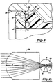
- the thickness T of the collecting lens 34 can be around .0745 inches (1.89 mm) (see Figure 9).
- the polycarbonate material of the collecting lens 34 can be of the type manufactured by General Electric and sold under the designation of Lexan QQ 2220 with a refractive index around 1.586.
- the curvature of the transparent outer casing 52 of the optical fiber also acts as a lens which can affect the transmission of light rays to the core portion 50.
- the lens defined by the lens track 62 is advantageously selected to direct the light rays into the optical fiber at an angle of incidence which will be compatible with the curvature of the casing 52 of the optical fiber such that the collected light is focused into the core portion 50.
- an optical light path diagram as illustrated by Figure 10 indicates that light in the vicinity of the target area and up to a generally conical or radial angle of around ⁇ 5 degrees, relative to the center of the aiming or viewing axis B, will be radially directed into the fluorescent core portion 50 of the fiber optic collector section 31.
- the lines shown in Figure 10 are examples of light rays impinging generally directly on the light collector section 31.
- light rays at angles up to about plus or minus 5 degrees will also pass into the fluorescent pigmented core portion 50 of the fiber optic collector section 31.
- the preceding embodiment of the present invention is sensitive to light in the vicinity of the target or scene as viewed by the operator. This is enhanced by the fiber optic collector section 31 and associated collecting lens 34 being contoured and located to generally surround the dichroic mirror 18 and hence surround the scene being viewed along the aiming or viewing axis B.
- the coils of the fiber optic collector section 31 are generally located in a single, generally unidirectional plane, i.e. within a common generally smoothly, continuously contoured envelope such as defined by a flat plane.
- This arrangement not only contributes to the response to light in the area of the target or scene to be viewed but also facilitates the construction and operation of the associated collecting lens 34 for focusing the light.
- an arcuate or generally, partially spherical plane could be used
- the amount of light generated by excitation of the fluorescent treated fiber optic core portion 50 of the collector section 31 can be significantly increased whereby the light transmitted can be maximized permitting the overall length of the collector section 31 to be minimized while still providing the desired level of illumination at the end face 46 of the transmission line 36 which end face defines the reticle pattern.
- the reticle pattern as defined by the core portion 50' at the end face 46 of the transmission line 36 will be a circular dot.
- a different shaped reticle pattern could be obtained by providing the transmission line 36 to have a diamond shaped core portion 50', as shown in Figure 8, which would be illuminated by the collector section 31 having the circular core portion 50 as shown in Figure 7.
- the length of the serpentine portion of the fiber optic collector section 31, which is exposed to ambient light at the front of the housing 14, was around 13 inches (33 cm).
- the cavity 28 housing the collector assembly 26 had a width W1 of around 1.195 inches (30.35 mm) and an overall height H of around 1.545 inches (39.24 mm) with the radius of curvature of the roof portion 64 being around .598 inches (15.19 mm).
- the width W2 of the housing 14 was around 1.34 inches (34.04 mm) while the overall length L was around 4.20 inches (106.7 mm).
- the retainer 32 is constructed from a black, non-light reflecting material.
- the retainer 32 was constructed of a carbon fiber filled thermoplastic material sold by the General Electric Company under the designation Ultem 7801 with the retainer 32 having a matte black finish.
- a contrast in color is also desirable. It is believed that for day and night sighting a reticle pattern having an amber or orangish hue is advantageous.
- the optical fiber of the core portion 50 of the collector section 31 was treated with a yellow fluorescent material which resulted in a reflected reticle pattern from the dichroic mirror or lens 18 of an amber or orangish hue for day sighting.
- the tritium lamp 48 having a green hue, causes, by fluorescence from the optical fiber of the collector core portion 50, the same amber color to appear in the reticle as viewed at night.
- the combination of the dominant yellow light from the fiber optic collector 30 and the wavelength of the dichroic mirror 18 will provide a reflected reticle pattern having an amber or orangish hue.
- the reticle pattern will still have an amber or orangish hue.
- the beam-splitting dichroic mirror or lens 18 is provided with a selective coating by which it is reflective over a certain range of wavelengths and transmissive over another range.
- the coating was selected to reflect light at a wavelength of from about 570 nm and higher and to transmit light of a wavelength below that level.
- the blue hues will be transmitted while the red hues will be reflected.
- the operator or viewer, looking through the sighting device 10 at the object or scene with only one eye, will see the latter in a slightly bluish tint.
- the outer surface of the dichroic mirror 18 can be provided with an antireflex coating to reduce losses.
- the fiber optic structure 30 may be desirable to make from a one-piece, continuous optical fiber for the collector section 31 and the transmission line 36.
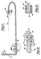
- Such an embodiment is shown in Figures 14 and 15 where components similar to like components in the embodiment of Figures 6 and 11 are given the same numeral designation with the addition of the letter postscript "a".
- the light collector section 31a and transmission line 36a are constructed of a single, continuous optical fiber.
- the optical fiber includes a fluorescent core portion 50a and transparent outer casing 52a. However, no cladding is used around core portion 50a, such as cladding 51.
- a protective . plastic RTV material 66 is applied to the transmission line 36a which acts to bond the line 36a to the adjacent inner wall of the housing 14 to thereby protect the line 36a from vibration.
- the tritium lamp 48a is optically coupled to the line 36a near its light emitting end.
- the protective RTV coating 66 could be used with a continuous optical pigmented fiber including the cladding 51 as shown in Figure 7 and similarly can be applied to any of the embodiments described herein.
- the reticle pattern is provided by the core portion 50 at the exposed end face 46 of the fiber optic transmission line 36.
- the outer diameter or peripheral shape of the transmission line core portion 50 forms the size and shape of the reticle pattern or aiming mark seen by the operator in the target or viewing area. This is a desirable feature of the present invention since the user will observe a sharp outline of the reticle pattern in the target or viewing area.
- the aiming mark is not sharp, but is observed in the dichroic mirror to have a starburst and generally imprecise shape and outline.
- the reticle mask 65 must have a clear aperture size and shape which is substantially, completely located within the confines of the fluorescent fiber core portion 50a.
- This structural arrangement will also avoid the starburst characteristic because the dichroic lens or mirror 18 can be focused on the aperture of the reticle mask 65 of glass 63 which is then fully illuminated by the flush mounted fiber optic core portion 50a through a proper numerical aperture.
- the inner surface 67 of the glass element 63 has a vacuum metalized, thin opaque coating which is etched to define the desired reticle pattern with the opaque coating blocking any other light therethrough from the end face 46a of the transmission line 36a.
- the thin opaque coating can be provided by vaporizing aluminum in a vacuum with the coating thickness being between around 500A° to 1500A° (Angstrom units).
- FIG. 18 Another form of optical circuit for use in the present invention is shown in Figures 18 and 19.
- components similar to like components of the prior embodiments will be given the same numeral designation with the addition of the letter postscript "b".
- the fiber optic structure 30b is constructed of the two piece fiber optic such as that shown in Figures 11 and 12; alternatively the structure 30b could be constructed of a single optic fiber such as in the fiber optic structure 30a shown in Figure 14.
- the optical fiber of the collector section 31b will be of the type having a fluorescent, pigmented core while the optical fiber of the transmission line 36b will be of the type having a clear, non-pigmented core.
- the tritium lamp 48b can illuminate a short length of red fluorescent cored fiber optic material or line 70.
- the red light is brought to the forward end of a GRIN lens assembly 72 comprising a cemented pair of gradient index (GRIN) lenses 69 and 71. This can be done with or without a coupling 79 to a length of clear optical fiber 77.
- GRIN gradient index
- a suitable dichroic coating 73 is place to selectively reflect red light but transmit amber light.
- the GRIN lens pair can combine the red image through reflection with the amber image by transmission and present a reticle pattern on the adjacent surface of the GRIN lens which is a combination of the day amber color and a red night color.
- Both the fiber optic transmission line 36b and the fiber optic line 70 can be interconnected by a coupling 72 to properly locate and superimpose the two images of the reticle pattern.
- the grin lenses 69 and 71 are of matching wavelengths of P/4, i.e. pitch/4. Couplings such as 35b, 72 and 79 for connecting optical fibers are well known in the art and hence the details thereof have been omitted for purposes of simplicity.
- the combined images form the reticle pattern on the exit face of the GRIN lens 71.
- the proper size and shape must be provided at the two input faces of the GRIN lenses 69 and 71.
- an illumination intensity from the light collector assembly 26 and from the tritium lamp 48, to the end face 46 or reticle pattern is desirable to have an illumination intensity from the light collector assembly 26 and from the tritium lamp 48, to the end face 46 or reticle pattern to provide a desired contrast level to accommodate the wide variations in the illumination intensity or illuminance of day sighting and at the same time to accommodate night sighting.
- the light intensity in daylight sighting can have extreme variations.
- the brightness, or illuminance of the scene being viewed can vary over a range of from about 1000 foot candles (FC) to around .1 foot candles (FC).
- FC foot candles
- FC .1 foot candles
- contrast ratio can be defined by the value of (DI-BI)/BI, where DI is the luminance of the reticle pattern as viewed in the dichroic mirror or lens 18 and BI is the luminance of the scene being viewed.
- DI the luminance of the reticle pattern as viewed in the dichroic mirror or lens 18
- BI the luminance of the scene being viewed.
- the illuminance values in foot candles are converted to units of luminance assuming the target scene is a Lambertian surface. This is required since the aiming dot is self-radiant. This assures that the reticle pattern will be clearly observable in viewing scenes at the upper end of illuminance while also providing that the reticle pattern will not wash out scenes being viewed at the lower end of illuminance.
- the present invention with illumination of the reticle pattern by the artificial tritium lamp 48 will maintain good contrast without washing out the background or target scene. This occurs, in part at least, because the amber color of the reticle pattern is presented to the dark adapted eye substantially in the center of the night blind spot.
- an opaque mask which is selectively moveable between the tritium lamp and the fluorescent core material of the fiber optic line, can be utilized.
- the base 16 is provided with a pair of threaded through bores 74 by which the sighting device 10 can be secured to the mounting bracket 13.
- a biasing spring 76 has one end located and held in a base seat 78 and the opposite end located and held in a housing seat 80.
- the base seat 78 and housing seat 80 are angulated at a common angle such that when the biasing spring 76 is located therein it is compressed in assembly and will be exerting a bias on the housing 14 urging it upwardly and outwardly (to the left as viewed in Figure 2) relative to the base 16.
- the base 16 has an outboard rib 82 with a longitudinally extending bore 83.
- a coil spring 84 is adapted to be located in the bore 83 in compressive engagement with a detent plunger 86.
- the housing 14 has a countersunk bore 88 adapted to receive a left-right adjustment screw 90 having a mating countersunk head.
- the threaded shank of the screw 90 extends into the housing 14, through a threaded bore 92 in a rib 94 located on the side of the base 16 opposite from the rib 82.
- a ratchet nut 96 is threadably, fixedly secured to the end of the shank of the left-right screw 90 at a position in line with the detent plunger 86.
- the ratchet nut 96 has its outer surface axially knurled or splined. Thus, when assembled, the detent plunger 86 will be urged into engagement with the splines of the ratchet nut 96. To make a left-right or windage adjustment of the sighting device 10, the screw 90 is simply threaded more or less into the bore 92 with the bias of the biasing spring 76 urging the housing 14 in the desired direction relative to the base 16. The ratchet nut 96 will rotate with the adjustment screw 90 to provide a feel for the indexing movement and an audible or tactile "click" sound or feedback to the operator caused by the ratcheting movement of the detent plunger 86.
- a sufficient number of splines are provided on the ratchet nut 96 to permit the slight left-right adjustments by indexing between adjacent splines.
- forty such splines were located at generally equal intervals over the circumference of ratchet nut 96.
- the engagement of the detent plunger 86 with the splines on the ratchet nut 96 will also provide an anti-rotation function to hold the housing 14 and base 16 in the desired relative position.
- the base 16 has an arm portion 98 extending longitudinally, rearwardly from one side.
- a threaded bore 100 extends generally vertically through the arm portion 98.
- a coil spring 102 and detent plunger 104 are identical to spring 84 and plunger 86 and are similarly located in a bore 106 extending into the base 16 at a position below and forwardly of the arm portion 98.
- An up-down or elevation adjustment screw 108 identical to screw 90, extends into housing 14 through a countersunk bore 109 and in threaded engagement with the threaded bore 100 in arm portion 98.
- the arm portion 98 is adapted to fit in a notch 112 located at the rearward end of the housing 14.
- a lower plate portion 114 of notch 112 has a through bore 116 adapted to receive the outer end of the shank of adjustment screw 108 in clearance relationship.
- a serrated ratchet nut 110 identical to ratchet nut 96, is threadably, fixedly secured to the outer end of the shank of adjustment screw 108.
- the ratchet nut 110 is spaced from the plate portion 114 and located in a position to be engaged by the detent plunger 104 which is below the plate portion 114.
- the screw 108 is simply threaded more or less into the threaded bore 100 whereby the back of the housing 14 will be pivoted vertically about the left-right adjustment screw 90 to the desired position.
- the bias of the biasing spring 76 will urge the housing 14 to the desired vertical position relative to the base 16.
- the ratchet nut 110 will rotate with the adjustment screw 108 and to provide a feel for the indexing movement and an audible or tactile "click" to the operator for each increment of rotation.
- the serrations on the ratchet nut 110 as engaged by the detent plunger 104 will provide a positive locking action.
- the total amount of movement both for the windage calibration via the left-right adjustment screw 90 and for elevation calibration via the elevation adjustment screw 108 is slight, i.e. generally around .05 inches (1.27 mm) for windage and around .05 inches (1.27 mm) for elevation. This slight movement provides at least around ⁇ 45 MOA of windage and elevation adjustment.
- both of the threaded bores 92 and 100 are radially slotted to minimize binding with the associated screws 90 and 108 resulting from adjustment.
- the level of ambient light utilized will be more nearly representative of the illumination level of the object or scene being viewed.
- the desired contrast will be provided with the object or scene being viewed with the effect, if any, of the illumination of the surrounding area being minimized.
- the fiber optic collector section 31 and associated collecting lens 34 being contoured and located to generally surround the dichroic mirror 18 and hence surround the aiming or viewing axis B.
- a desired level of brightness of the reticle pattern can be provided substantially over the full range of light intensity from daylight, to twilight, to night and dawn.
- the retainer 32 could be provided with a reflective surface in confrontation with the light collector section 31 and the collecting lens 34.
- the collecting lens 34 could have its outer radius and other optical characteristics suitably revised so that light rays which do not intersect the fluorescent core of the fiber can strike a mirror reflective surface.
- This mirror surface could be a first surface mirror, or an internally reflecting mirror in combination with other molded clear plastic lens elements of the Mangin type. The mirror design would reflect light rays that miss the fluorescent core on the first passage and are thus reflected and focused into the fluorescent core portion 50.
- This structure could be utilized in the embodiments previously illustrated by providing the retainer 32 with a reflective surface constructed of aluminized Lexan.
Landscapes
- Physics & Mathematics (AREA)
- Optics & Photonics (AREA)
- Engineering & Computer Science (AREA)
- General Engineering & Computer Science (AREA)
- Astronomy & Astrophysics (AREA)
- General Physics & Mathematics (AREA)
- Telescopes (AREA)
Claims (35)
- Source de lumière pour un dispositif de visée pour visualiser une scène ou un objet et ayant une structure de réticule (46, 50', 51') pour fournir un motif de réticule (50') à utiliser pour visualiser la scène ou l'objet, où la source de lumière est destinée à illuminer le motif de réticule (50') et comporte:ledit moyen de source de lumière ambiante (26) comportant un collecteur de lumière à fibres optiques (31) défini par une première fibre optique constituée d'une matière activée par la lumière pour fournir une illumination en réponse à une lumière frappant celle-ci, ladite première fibre optique ayant une longueur présélectionnée et adaptée pour recevoir une lumière dirigée radialement vers l'intérieur dans ladite première fibre optique sur ladite longueur présélectionnée afin de fournir un niveau déterminable d'illumination pour la structure de réticule (46, 50', 51') pour fournir un niveau voulu de luminosité pour ledit motif de réticule (50');un moyen de source de lumière ambiante (26) pour recevoir une lumière ambiante et pour fournir une illumination provenant d'une lumière ambiante à la structure de réticule (46, 50', 51') pour illuminer le motif de réticule (50');
ledit moyen de source de lumière ambiante (26) comportant une structure de lentille (34) connectée opérationnellement audit collecteur de lumière à fibres optiques (31) pour focaliser une lumière ambiante radialement vers l'intérieur dans ladite première fibre optique généralement sur ladite longueur présélectionnée. - Source de lumière selon la revendication 1, dans laquelle ladite matière activée par la lumière fournit une illumination ayant une longueur d'onde généralement d'environ 570 nm. Et plus.
- Dispositif de visée à utiliser de jour et de nuit pour visualiser une scène ou un objet, comportant la source de lumière selon la revendication 1;
ladite structure de réticule (46, 50', 51') pour fournir un motif de réticule (50') à utiliser dans le pointage dudit dispositif de visée,
un second moyen de source de lumière comportant une source de lumière artificielle (48) et pour fournir une illumination provenant de ladite source de lumière artificielle (48) à ladite structure de réticule (46, 50', 51') pour illuminer ledit motif de réticule (50');
des moyens de fibre optique (33, 35) opérationnellement connectés auxdits premier (26) et second (48) moyens de source de lumière pour transmettre la lumière obtenue dudit collecteur de lumière à fibres optiques (31) et de ladite source de lumière artificielle (48) à ladite structure de réticule (46, 50', 51'),
des moyens de division de faisceau (18) pour transmettre des ondes lumineuses sur une première plage de longueurs d'onde et réfléchir des ondes lumineuses sur une seconde plage de longueurs d'onde et adaptés pour recevoir la scène ou l'objet visualisé et transmettre la scène ou l'objet avec une lumière ayant une longueur d'onde dans ladite première plage de longueurs d'onde;
lesdits premier (26) et second (48) moyens de source de lumière et lesdits moyens de fibre optique (33, 35) étant opérationnels pour transmettre une lumière ayant une longueur d'onde dans ladite seconde plage de longueurs d'onde;
ladite structure de réticule (46, 50', 51') recevant une illumination desdits moyens de fibre optique (33, 35) et projetant ledit motif de réticule (50') sur lesdits moyens de division de faisceau (18) pour produire une image réfléchie dudit motif de réticule (50') dans ladite seconde plage de longueurs d'onde superposée sur la scène ou l'objet visualisé et transmis par lesdits moyens de division de faisceau (18) dans ladite première plage de longueurs d'onde. - Dispositif de visée selon la revendication 3, dans lequel ladite fibre optique dudit collecteur de lumière à fibres optiques (31) a une partie de noyau (50) et une gaine extérieure (51), ladite partie de noyau (50) incluant une matière activée par la lumière pour fournir une illumination à une longueur d'onde présélectionnée dans ladite première plage en réponse à la lumière ambiante, ladite gaine (51) étant généralement transparente pour permettre à la lumière ambiante de passer radialement à travers celle-ci pour frapper la matière activée par la lumière de ladite partie de noyau (50), ladite structure de lentille (34) étant adaptée pour focaliser la lumière ambiante radialement dans ladite partie de noyau (50);
ladite source de lumière artificielle (48) étant un élément radioluminescent;
ladite structure de réticule (46, 50', 51') comportant un ensemble de lentilles à Gradient d'Indice (GRIN) (72) incluant une paire de lentilles GRIN (69, 71) reliés par une couche dichroïque (73), ladite couche dichroïque (73) étant adaptée pour transmettre des ondes lumineuses sur une plage de longueurs d'onde et pour réfléchir des ondes lumineuses sur une autre plage de longueurs d'onde, ladite plage et ladite autre plage de longueurs d'onde étant dans ladite seconde plage de longueurs d'onde desdits moyens de division de faisceau (18);
l'un parmi lesdits premier (31b) et second (48b) moyens de source de lumière étant connecté audit ensemble de lentilles GRIN (72) et adapté pour produire des ondes lumineuses dans ladite plage de longueurs d'onde, et
l'autre parmi lesdits premier (31b) et second (48b) moyens de source de lumière étant connecté audit ensemble de lentilles GRIN (72) et adapté pour produire des ondes lumineuses dans ladite autre plage de longueurs d'onde. - Dispositif de visée selon la revendication 4, dans lequel ledit noyau (50) de l'un parmi lesdits premier (31b) et second (48b) moyens de source de lumière est connecté à une première lentille (69) desdites lentilles GRIN pour transmettre des ondes lumineuses de ladite une plage de longueurs d'onde pour passer à travers ladite couche dichroïque (73) et à travers la seconde lentille (71) desdites lentilles GRIN et hors dudit ensemble de lentilles GRIN (72) vers lesdits moyens de division de faisceau (18),
ledit autre parmi lesdits premiers et seconds moyens de source de lumière étant connectés à ladite seconde lentille parmi lesdites lentille GRIN pour transmettre des ondes lumineuses de ladite autre plage de longueurs d'onde à réfléchir par ladite couche dichroïque (73) et hors dudit ensemble de lentilles GRIN (72) vers lesdits moyens de division de faisceau. - Dispositif de visée selon la revendication 5, lesdites première et seconde lentilles GRIN (69, 71) étant ajustées pour focaliser les ondes lumineuses transmises à travers ladite couche dichroïque (73) et les ondes lumineuses réfléchies par ladite couche dichroïque (73) afin de produire des motifs de réticule qui coïncident sensiblement.
- Dispositif de visée pour visualiser une scène ou un objet, comportant la source de lumière selon la revendication 1;
ladite structure de réticule (46, 50', 51') fournissant ledit motif de réticule (50') à utiliser dans le pointage dudit dispositif de visée,
des fibres optiques (33, 35) opérationnellement connectée audit moyen de source de lumière ambiante (26) pour transmettre la lumière obtenue depuis ledit collecteur de lumière à fibres optiques (31) à ladite structure de réticule (46, 50', 51'),
des moyens de division de faisceau (18) pour transmettre des ondes lumineuses sur une première plage de longueurs d'onde et réfléchir des ondes lumineuses sur une seconde plage de longueurs d'onde et adaptés pour recevoir la scène ou l'objet visualisé et pour transmettre la scène ou l'objet avec une lumière ayant une longueur d'onde dans ladite première plage de longueurs d'onde,
ledit moyen de source de lumière ambiante (26) et lesdits moyens de fibre optique (33, 35) étant opérationnels pour transmettre de une lumière ayant une longueur d'onde dans ladite seconde plage de longueurs d'onde;
ladite structure de réticule (46, 50', 51") recevant une illumination desdits moyens de fibre optique (33, 35) et projetant ledit motif de réticule (50') sur lesdits moyens de division de faisceau (18) pour produire une image réfléchie dudit motif de réticule (50') dans ladite seconde plage de longueurs d'onde superposée sur la scène ou l'objet visualisé et transmis par lesdits moyens de division de faisceau (18) dans ladite première plage de longueurs d'onde,
ledit moyen de source de lumière ambiante (26) comportant une structure de lentille (34) opérationnellement connectée audit collecteur de lumière à fibres optiques (31) pour focaliser une lumière ambiante radialement vers l'intérieur dans ladite première fibre optique (31) généralement sur ladite longueur présélectionnée. - Dispositif de visée selon la revendication 7, dans lequel ladite longueur présélectionnée de ladite première fibre optique (31) fournit un taux de contraste prédéterminé entre l'illuminance dudit motif de réticule (50') et l'illuminance de la scène ou de l'objet visualisé, ledit taux de contraste étant déterminé par la relation (DI-BI)/BI où DI est l'illuminance en candelas par pied dudit motif de réticule tel que visualisé par l'opérateur et BI est l'illuminance de la scène ou de l'objet visualisé et ledit taux de contraste prédéterminé étant dans une plage comprise entre environ 200 et environ 250 sur une plage d'illuminance de la scène comprise entre environ 305 LUX (1000 candelas par pied) et environ 0,003 LUX (0,1 candela par pied).
- Dispositif de visée selon la revendication 8, dans lequel ledit taux de contraste est généralement d'environ 230 sur ladite plage d'illuminance de la scène ou de l'objet.
- Dispositif de visée selon la revendication 7 ou source de lumière selon la revendication 1, où ladite première fibre optique dudit collecteur de lumière à fibres optiques (31) a une partie de noyau (50) et un gainage extérieur (52), ladite partie de noyau (50) incluant une matière activée par la lumière pour fournir une illumination à une longueur d'onde présélectionnée en réponse à la lumière ambiante dirigée dans ladite partie de noyau (50), ledit gainage (52) étant généralement transparent pour permettre à la lumière ambiante de passer radialement à travers celui-ci pour frapper ladite matière activée par la lumière de ladite partie de noyau (50).
- Dispositif de visée ou source de lumière selon la revendication 10, où ladite structure de lentille (34) est adaptée pour être placée à proximité de ladite première fibre optique dudit premier collecteur de lumière à fibres optiques (31) et ayant une structure de lentille adaptée pour focaliser la lumière ambiante radialement dans ladite partie de noyau (50) de ladite fibre optique généralement sur ladite longueur présélectionnée.
- Dispositif de visée ou source de lumière selon la revendication 11, où ledit gainage extérieur (52) a généralement une forme arquée capable de fournir un effet de lentille, ladite structure de lentille (34) étant munie d'un point focal prédéterminé sélectionné par rapport à l'effet de lentille dudit gainage extérieur (52) pour fournir une focalisation combinée de la lumière ambiante radialement dans ladite partie de noyau (50).
- Dispositif de visée selon la revendication 3 ou 7 ou source de lumière selon la revendication 1, où ledit collecteur de lumière à fibres optiques (31) est défini par un agencement généralement en serpentin de ladite première fibre optique et est placé dans un plan.
- Dispositif de visée ou source de lumière selon la revendication 13, où ladite structure de lentille (34) inclut une piste de lentille ayant une forme en serpentin sensiblement similaire audit agencement en serpentin dudit collecteur de lumière à fibres optiques (31) et située généralement à l'opposé de celui-ci, grâce à quoi la lumière ambiante reçue sera focalisée généralement sur ladite longueur présélectionnée de ladite première fibre optique.
- Dispositif de visée ou source de lumière selon la revendication 14, où ledit premier moyen de source de lumière (26) comportent un élément de retenue (32) ayant une structure de gorge ayant ledit agencement en serpentin de ladite première fibre optique (31) et adapté pour recevoir ladite première fibre optique (31) et supporter ladite première fibre optique pour retenir ledit agencement en serpentin.
- Dispositif de visée ou source de lumière selon la revendication 15, où ledit dispositif de visée inclut un boítier (22) et inclut des moyens de support (28, 55) opérationnellement connectés audit boítier (22) pour supporter ledit collecteur à fibres optiques (31), ladite structure de lentille (34) et ledit élément de retenue (32) et lesdits moyens de division de faisceau (18) à l'aide d'une partie dudit agencement en serpentin généralement entourant lesdits moyens de division de faisceau (18).
- Dispositif de visée ou source de lumière selon la revendication 15, où ledit élément de retenue (32) a une surface réfléchissante à l'opposé de ladite première fibre optique pour réfléchir une lumière dans ladite première fibre optique.
- Dispositif de visée selon la revendication 3, dans lequel lesdits moyens de fibre optique comportent une seconde fibre optique (36) ayant une extrémité luminescente, ladite extrémité luminescente de ladite seconde fibre optique définissant essentiellement la forme dudit motif de réticule (50').
- Dispositif de visée ou source de lumière selon la revendication 16 ou la revendication 18, où lesdits moyens de division de faisceau (18) sont un miroir dichroïque ayant un axe de visée pour visualisation par l'opérateur et pour réception directe de la scène ou de l'objet visualisé le long dudit axe de visée.
- Dispositif de visée ou source de lumière selon la revendication 19, où ledit miroir dichroïque réfléchit des longueurs d'onde de lumière d'environ 570 nm et plus et transmet des longueurs d'onde de lumière plus basses.
- Dispositif de visée à utiliser de jour et de nuit pour visualiser une scène ou un objet le long d'un axe de visée, comportant la source de lumière selon la revendication 1;
ladite structure de réticule (46, 50', 51') pour fournir ledit motif de réticule (50') à utiliser dans le pointage dudit dispositif de visée,
une ligne de fibre optique (36) opérationnellement connectée audit collecteur de lumière à fibres optiques (31);
ledit collecteur de lumière à fibres optiques (31) fournissant une illumination à l'extrémité luminescente (46) de ladite ligne de fibre optique (36);
des moyens de fibre optique (33, 35) connectés à ladite seconde source (48) de lumière pour délivrer une illumination à ladite extrémité luminescente (46) de ladite ligne de fibre optique (36);
et des moyens de division de faisceau comportant un miroir dichroïque non-télescopique (18) opérationnel pour réfléchir des longueurs d'onde de lumière sur une première plage et pour transmettre des longueurs d'onde sur une seconde plage, ledit miroir dichroïque (18) ayant un axe central généralement aligné sur l'axe de visée, grâce à quoi la scène ou l'objet est visualisé à travers ledit miroir dichroïque (18),
ladite structure de réticule (46, 50', 51') recevant une illumination de ladite extrémité luminescente (46) dans ladite première plage de longueurs d'onde et projetant ledit motif de réticule (50') sur ledit miroir dichroïque (18) pour produire une image réfléchie dudit motif de réticule (50') superposée sur l'image ou l'objet visualisé. - Dispositif de visée selon la revendication 21, dans lequel ladite extrémité luminescente(46) de ladite ligne de fibre optique (36) définit essentiellement la forme dudit motif de réticule (50').
- Dispositif de visée selon la revendication 21, incluant une seconde source de lumière qui est une source (48) de lumière artificielle et des moyens de fibre optique (36) pour fournir une illumination à ladite structure de réticule (46, 50', 51') à partir de ladite seconde source de lumière (48).
- Dispositif de visée selon la revendication 23, dans lequel lesdits moyens de fibre optique (36) fournissent une illumination provenant desdites première (26) et seconde (48) sources de lumière à ladite extrémité luminescente (46) de ladite ligne de fibre optique.
- Dispositif de visée selon la revendication 24, dans lequel ladite extrémité luminescente (46) de ladite ligne de fibre optique définit essentiellement la forme dudit réticule (50').
- Dispositif de visée selon la revendication 25, dans lequel ledit miroir dichroïque (18) dans ladite première plage réfléchit des longueurs d'onde de lumière d'environ 570 nm et plus et dans ladite seconde plage transmet des longueurs d'onde de lumière plus basses.
- Dispositif de visée selon la revendication 26, dans lequel ladite source (48) de lumière artificielle est une source radioluminescente.
- Dispositif de visée selon la revendication 21, dans lequel ladite fibre optique dudit collecteur de lumière à fibres optiques (31) a une partie de noyau (50) et une gaine extérieure (51), ladite partie de noyau (50) incluant une matière activée par la lumière pour fournir une illumination à une longueur d'onde présélectionnée dans ladite première plage en réponse à la lumière ambiante, ladite gaine (51) étant généralement transparente pour permettre à la lumière ambiante de passer radialement à travers celle-ci pour frapper la matière activée par la lumière de ladite partie de noyau (50), ladite structure de lentille (34) étant adaptée pour focaliser la lumière ambiante radialement dans ladite partie de noyau (50).
- Dispositif de visée selon la revendication 21, incluant une seconde source de lumière qui est une source (48) de lumière artificielle et ladite fibre optique dudit collecteur de lumière à fibres optiques (31) ayant une partie de noyau (50) et une gaine extérieure (51), ladite partie de noyau (50) incluant une matière activée par la lumière pour fournir une illumination à une longueur d'onde présélectionnée dans ladite première plage en réponse à la lumière ambiante, ladite gaine (51) étant généralement transparente pour permettre à la lumière ambiante de passer radialement à travers celle-ci pour frapper la matière activée par la lumière de ladite partie de noyau (50), ladite structure de lentille (34) étant adaptée pour focaliser la lumière ambiante radialement dans ladite partie de noyau (50),
ladite source (48) de lumière artificielle étant une source radioluminescente,
ladite ligne de fibre optique (36) étant constituée essentiellement de la même matière activée par la lumière que ledit collecteur de lumière à fibres optiques (31),
lesdits moyens de fibre optique (33, 35) couplant ladite source radioluminescente sensiblement directement sur ladite ligne de fibre optique (33) pour transmettre une lumière depuis ladite source radioluminescente vers ladite extrémité luminescente (46). - Dispositif de visée selon la revendication 29, dans lequel ladite structure de réticule inclut un masque (65) ayant ledit motif de réticule, ledit masque (65) étant connecté à ladite extrémité luminescente de ladite ligne de fibre optique.
- Dispositif de visée selon la revendication 21, incluant une seconde source de lumière qui est une source (48) de lumière artificielle et où ladite fibre optique dudit collecteur de lumière à fibres optiques (31) a une première partie de noyau (50) et une première gaine extérieure (51), ladite première partie de noyau (50) incluant une matière activée par la lumière pour fournir une illumination à une longueur d'onde présélectionnée dans ladite première plage en réponse à la lumière ambiante, ladite première gaine (51) étant généralement transparente pour permettre à la lumière ambiante de passer radialement à travers celle-ci pour frapper la matière activée par la lumière de ladite première partie de noyau (50), ladite structure de lentille (34) étant adaptée pour focaliser la lumière ambiante radialement dans ladite première partie de noyau (50),
ladite source (48) de lumière artificielle étant une source radioluminescente,
ladite ligne de fibre optique (36) étant constituée d'une fibre optique ayant une seconde partie de noyau et une seconde gaine extérieure, ladite seconde partie de noyau étant sensiblement incolore et sans matière activée par la lumière,
lesdits moyens de fibre optique couplant ladite source radioluminescente à ladite ligne de fibre optique (36) à travers une partie de fibre optique (33) ayant une partie de noyau et une gaine extérieure, la partie de noyau incluant une matière activée par la lumière - Dispositif de visée selon la revendication 31, dans lequel ladite partie de fibre optique (33) est une partie de ladite fibre optique dudit collecteur de lumière à fibres optiques (31).
- Dispositif de visée selon la revendication 31, dans lequel ladite structure de réticule inclut un masque (65) ayant ledit motif de réticule, ledit masque (65) étant connecté à ladite extrémité luminescente de ladite ligne de fibre optique (36).
- Dispositif de visée pour visualiser une scène ou un objet, comportant la source de lumière selon la revendication 1;
ladite structure de réticule (46, 50', 51') fournissant ledit motif de réticule (50') à utiliser dans le pointage dudit dispositif de visée,
et des moyens de division de faisceau (18);
ledit collecteur de lumière à fibres optiques (31) fournissant une illumination à ladite structure de réticule (46, 50', 51'), ledit motif de réticule (50') étant projeté sur lesdits moyens de division de faisceau (18) pour produire une image réfléchie dudit motif de réticule (50') superposée sur l'image ou l'objet visualisé, ladite fibre optique dudit collecteur de lumière à fibres optiques (31) ayant une partie de noyau (50) et une gaine extérieure (51), ladite partie de noyau (50) incluant une matière fluorescente pour fournir une illumination ayant une longueur d'onde présélectionnée en réponse à la lumière ambiante, ladite gaine (51) étant généralement transparente pour permettre à la lumière ambiante de passer radialement à travers celle-ci pour frapper la matière fluorescente de ladite partie de noyau. - Dispositif de visée selon la revendication 34, incluant une source (48) de lumière artificielle, des moyens de fibre optique (33, 35) connectés à ladite seconde source de lumière (48) pour fournir une illumination à ladite structure de réticule (46, 50', 51') pour fournir une illumination pour ledit motif de réticule (50') pour une vision de nuit.
Applications Claiming Priority (3)
| Application Number | Priority Date | Filing Date | Title |
|---|---|---|---|
| US449825 | 1995-05-24 | ||
| US08/449,825 US5653034A (en) | 1995-05-24 | 1995-05-24 | Reflex sighting device for day and night sighting |
| PCT/US1996/008091 WO1996037750A1 (fr) | 1995-05-24 | 1996-05-17 | Dispositif de vision reflexe pour la vision de jour et de nuit |
Publications (3)
| Publication Number | Publication Date |
|---|---|
| EP0830559A1 EP0830559A1 (fr) | 1998-03-25 |
| EP0830559A4 EP0830559A4 (fr) | 1998-07-29 |
| EP0830559B1 true EP0830559B1 (fr) | 2004-03-03 |
Family
ID=23785652
Family Applications (1)
| Application Number | Title | Priority Date | Filing Date |
|---|---|---|---|
| EP96924255A Expired - Lifetime EP0830559B1 (fr) | 1995-05-24 | 1996-05-17 | Dispositif de vision reflexe pour la vision de jour et de nuit |
Country Status (5)
| Country | Link |
|---|---|
| US (1) | US5653034A (fr) |
| EP (1) | EP0830559B1 (fr) |
| DE (1) | DE69631759D1 (fr) |
| WO (1) | WO1996037750A1 (fr) |
| ZA (1) | ZA963824B (fr) |
Cited By (1)
| Publication number | Priority date | Publication date | Assignee | Title |
|---|---|---|---|---|
| WO2015055596A1 (fr) | 2013-10-17 | 2015-04-23 | Mb-Microtec Ag | Dispositif de visée |
Families Citing this family (98)
| Publication number | Priority date | Publication date | Assignee | Title |
|---|---|---|---|---|
| US5442861A (en) | 1993-12-23 | 1995-08-22 | Lorocco; Paul M. | Sight pin and holder for archery bow |
| US5926963A (en) * | 1996-11-15 | 1999-07-27 | Modern Muzzleloading, Inc. | Fiber optic forward sight for rifle barrels |
| JPH10185495A (ja) * | 1996-12-18 | 1998-07-14 | Asia Opt Kk | 照準スコープ |
| US5956854A (en) * | 1996-12-26 | 1999-09-28 | Tru-Glo, Inc. | Day/night weapon sight |
| US6122833A (en) * | 1996-12-26 | 2000-09-26 | Tru-Glo, Inc. | Day/night weapon sight |
| US6111692A (en) * | 1997-07-28 | 2000-08-29 | Litton Systems, Inc. | Multi-function day/night observation, ranging, and sighting device and method of its operation |
| US5924234A (en) * | 1997-11-20 | 1999-07-20 | Trijicon, Inc. | Optical sighting device |
| US6418633B1 (en) * | 2000-06-30 | 2002-07-16 | Trophy Ridge, Llc | Vertical in-line bow sight |
| US6725854B1 (en) * | 2001-01-26 | 2004-04-27 | Abbas Ben Afshari | Illuminated sight pin |
| USD472256S1 (en) | 2002-06-17 | 2003-03-25 | Trijicon, Inc. | Sighting device |
| USD472569S1 (en) | 2002-06-17 | 2003-04-01 | Trijicon, Inc. | Sighting device |
| US6802131B1 (en) * | 2002-09-05 | 2004-10-12 | Raytheon Company | Side-illuminated target structure having uniform ring illumination |
| US6807742B2 (en) * | 2002-09-06 | 2004-10-26 | Trijicon, Inc. | Reflex sight with multiple power sources for reticle |
| USD492747S1 (en) | 2002-11-13 | 2004-07-06 | Truglo, Inc. | Rear sight for firearms |
| US20050138824A1 (en) * | 2003-12-24 | 2005-06-30 | Afshari Abbas B. | Fiber optic sight pin |
| US7257920B1 (en) * | 2004-03-26 | 2007-08-21 | The United Stated Of America As Represented By The Secretary Of The Navy | Aiming device |
| USD522083S1 (en) | 2004-04-23 | 2006-05-30 | Abbas Ben Afshari | Bow sight pin |
| US7552558B1 (en) * | 2004-06-26 | 2009-06-30 | Marlin Daniel Ballard | Mirror sight apparatus with integral rear sight |
| US6967775B1 (en) * | 2004-07-13 | 2005-11-22 | Millett Industries, Inc. | Zoom dot sighting system |
| US20060123687A1 (en) * | 2004-12-14 | 2006-06-15 | North Pass, Ltd. | Aiming sight |
| US7676981B2 (en) * | 2005-05-27 | 2010-03-16 | Defense Holdings, Inc. | Photoluminescent (PL) weapon sight illuminator |
| US7876434B2 (en) * | 2005-12-12 | 2011-01-25 | California Institute Of Technology | Color camera computed tomography imaging spectrometer for improved spatial-spectral image accuracy |
| WO2007087372A2 (fr) * | 2006-01-24 | 2007-08-02 | California Institute Of Technology | Modulation d'image spatiale permettant d'améliorer les performances d'un spectromètre d'imagerie par tomodensitométrie |
| US7877921B1 (en) | 2006-03-06 | 2011-02-01 | Raytheon Company | Method and apparatus for combining light from two sources to illuminate a reticle |
| US7428796B1 (en) | 2006-03-06 | 2008-09-30 | Raytheon Company | Method and apparatus for using a lens to enhance illumination of a reticle |
| US8215024B1 (en) * | 2006-04-15 | 2012-07-10 | Michael Terzo | Sighting device for a weapon |
| US7869125B2 (en) * | 2006-04-17 | 2011-01-11 | Raytheon Company | Multi-magnification viewing and aiming scope |
| US7503122B2 (en) * | 2006-07-07 | 2009-03-17 | Abbas Ben Afshari | Bow sight with sighting aperture |
| US7574810B1 (en) * | 2006-07-18 | 2009-08-18 | Truglo, Inc. | Illuminated reflective sighting device |
| US8713845B1 (en) | 2006-08-01 | 2014-05-06 | Raytheon Canada Limited | Method and apparatus for efficiently collecting radiation |
| US7905045B1 (en) * | 2006-11-02 | 2011-03-15 | Swan Richard E | Mounting assembly with adjustable spring tension |
| US7757423B1 (en) * | 2006-11-02 | 2010-07-20 | Swan Richard E | Mounting assembly with adjustable spring tension |
| US7869058B2 (en) * | 2006-11-16 | 2011-01-11 | Restaino Sergio R | Apparatuses and methods for evaluating performance of optical systems |
| US7876501B2 (en) | 2007-02-05 | 2011-01-25 | Raytheon Company | Optical sight having an unpowered reticle illumination source |
| US7652818B2 (en) * | 2007-02-05 | 2010-01-26 | Raytheon Company | Optical sight having an unpowered reticle illumination source |
| GB2486368A (en) * | 2007-05-22 | 2012-06-13 | Trijicon Inc | Optical sight |
| US7814669B2 (en) * | 2007-06-18 | 2010-10-19 | Kingsbury Klint M | Multi-spot adjustable reflex bow sight |
| US8006395B2 (en) * | 2007-06-18 | 2011-08-30 | Kingsbury Klint M | Multi-spot adjustable reflex bow and subsonic weapon sight |
| KR100906159B1 (ko) * | 2007-07-06 | 2009-07-03 | 정인 | 대구경 도트 사이트 장치 |
| US7821708B2 (en) * | 2007-10-24 | 2010-10-26 | Raytheon Company | Method and apparatus for illuminating a reticle |
| US20090113778A1 (en) * | 2007-11-02 | 2009-05-07 | Burris Company | Reduced eye relief, co-witnessing sight mount |
| US20090193705A1 (en) * | 2008-02-06 | 2009-08-06 | Truglo, Inc. | Sighting Device with Trajectory Compensation |
| ES2326064B1 (es) * | 2008-03-28 | 2010-07-13 | Francisco Santi Soriano Romero | Dispositivo visor accesorio para armas de fuego. |
| US20100077646A1 (en) * | 2008-09-30 | 2010-04-01 | Leonid Gaber | Quick-acquisition optical sight with red-dot-indication function |
| US8879146B2 (en) * | 2008-09-30 | 2014-11-04 | Truglo, Inc. | Reflective dot sighting device with perceived dot location |
| US8215050B2 (en) * | 2008-10-02 | 2012-07-10 | Trijicon, Inc. | Optical sight |
| US20100088944A1 (en) * | 2008-10-02 | 2010-04-15 | Callihan Rick | Illuminated Sight for use with Firearms and other instruments |
| US20100212208A1 (en) * | 2009-02-25 | 2010-08-26 | Sims Vibration Laboratory, Inc. | Optical sighting devices |
| US20110138639A1 (en) | 2009-06-10 | 2011-06-16 | Performance Indicator Llc | Photoluminescent optical sights and devices and methods therefrom |
| GB0913818D0 (en) * | 2009-08-07 | 2009-09-16 | Thermoteknix Systems Ltd | Light guiding device |
| US8599481B2 (en) * | 2009-08-20 | 2013-12-03 | Kruger Optical, Inc. | Flat walled scope and method of manufacturing the same |
| US8379307B2 (en) * | 2009-08-20 | 2013-02-19 | Yt Products, Llc | Dual mode reflex and telescopic sight combination |
| CA2769681C (fr) * | 2009-08-20 | 2017-08-01 | Yt Products, Llc | Viseur reflex et optique combine a mode double |
| US8919650B2 (en) | 2010-05-06 | 2014-12-30 | Browe, Inc | Optical device |
| US8869784B2 (en) * | 2011-06-24 | 2014-10-28 | Truglo, Inc. | Illuminated sighting device with removable optical fibers |
| WO2013024155A1 (fr) | 2011-08-17 | 2013-02-21 | Inserm (Institut National De La Sante Et De La Recherche Medicale) | Combinaisons d'anticorps anti-facteur d'entrée de vhc et d'agents antiviraux à action directe pour le traitement et la prévention de l'infection par le vhc |
| WO2013024157A2 (fr) | 2011-08-17 | 2013-02-21 | INSERM (Institut National de la Santé et de la Recherche Médicale) | Combinaisons d'agents ciblant un hôte pour le traitement et la prévention d'une infection par le vhc |
| WO2013024156A2 (fr) | 2011-08-17 | 2013-02-21 | INSERM (Institut National de la Santé et de la Recherche Médicale) | Combinaisons d'anticorps contre le facteur d'entrée du vhc et d'interférons pour le traitement et la prévention d'une infection par le vhc |
| WO2013024158A1 (fr) | 2011-08-17 | 2013-02-21 | INSERM (Institut National de la Santé et de la Recherche Médicale) | Combinaisons d'inhibiteurs de protéine kinase et d'interférons ou d'inhibiteurs de protéine kinase et d'antiviraux agissant directement pour le traitement et la prévention d'une infection par le vhc |
| US8966805B2 (en) | 2011-09-02 | 2015-03-03 | Trijicon, Inc. | Reflex sight |
| KR101375457B1 (ko) | 2012-09-27 | 2014-03-17 | 정보선 | 권총용 도트사이트 장치 |
| KR101394738B1 (ko) * | 2012-10-09 | 2014-05-15 | 정보선 | 권총용 도트사이트 장치 |
| KR101375373B1 (ko) * | 2012-10-22 | 2014-03-17 | 정보선 | 도트사이트 장착용 권총 슬라이드 |
| CN103246111A (zh) * | 2013-05-23 | 2013-08-14 | 深圳市华星光电技术有限公司 | 背光模组及液晶显示装置 |
| US9335118B1 (en) | 2014-01-08 | 2016-05-10 | Jason Stewart Jackson | Fiber optic weapon sight |
| US9587910B1 (en) | 2014-01-08 | 2017-03-07 | Jason Stewart Jackson | Fiber optic weapon sight |
| US9423212B2 (en) * | 2014-01-13 | 2016-08-23 | Leupold & Stevens, Inc. | Reflex sight adjustments |
| EP3172524B1 (fr) | 2014-07-22 | 2020-10-07 | N2 Imaging Systems, LLC | Combinaison de vidéo et de viseur optique |
| US9829277B2 (en) * | 2014-07-28 | 2017-11-28 | ZEROlight LLC | Illumination system for weapon optics |
| KR102323147B1 (ko) * | 2015-04-15 | 2021-11-05 | 정보선 | 도트 사이트 조준기 |
| US20180156573A1 (en) * | 2015-05-15 | 2018-06-07 | Ronnie Rex Capson | Backlit sighting device |
| US9797684B2 (en) * | 2015-07-08 | 2017-10-24 | Gregory E. Summers | Archery scope |
| WO2017015668A1 (fr) * | 2015-07-23 | 2017-01-26 | Campbell Robert Marshall | Viseur d'arme à feu avec miroir réglable |
| US10113837B2 (en) | 2015-11-03 | 2018-10-30 | N2 Imaging Systems, LLC | Non-contact optical connections for firearm accessories |
| US10393480B2 (en) * | 2017-05-16 | 2019-08-27 | Meopta U.S.A., Inc. | Target acquisition improvements using patterned dichroic coatings |
| US10578404B2 (en) | 2017-06-05 | 2020-03-03 | Richard E. Swan | Mounting assembly with metal injection molded lever and selective threaded governor post |
| US11466960B2 (en) | 2017-06-21 | 2022-10-11 | Christopher Noskowicz | Intensity adapting optical aiming reticle |
| EP3692323B1 (fr) | 2017-10-06 | 2022-06-15 | Raytheon Canada Limited | Mécanique de pivot pour visée réflexe à cadre ouvert |
| US10753709B2 (en) | 2018-05-17 | 2020-08-25 | Sensors Unlimited, Inc. | Tactical rails, tactical rail systems, and firearm assemblies having tactical rails |
| US10645348B2 (en) | 2018-07-07 | 2020-05-05 | Sensors Unlimited, Inc. | Data communication between image sensors and image displays |
| US11079202B2 (en) | 2018-07-07 | 2021-08-03 | Sensors Unlimited, Inc. | Boresighting peripherals to digital weapon sights |
| US10742913B2 (en) | 2018-08-08 | 2020-08-11 | N2 Imaging Systems, LLC | Shutterless calibration |
| US10921578B2 (en) | 2018-09-07 | 2021-02-16 | Sensors Unlimited, Inc. | Eyecups for optics |
| US11122698B2 (en) | 2018-11-06 | 2021-09-14 | N2 Imaging Systems, LLC | Low stress electronic board retainers and assemblies |
| US10801813B2 (en) | 2018-11-07 | 2020-10-13 | N2 Imaging Systems, LLC | Adjustable-power data rail on a digital weapon sight |
| US10796860B2 (en) | 2018-12-12 | 2020-10-06 | N2 Imaging Systems, LLC | Hermetically sealed over-molded button assembly |
| US11143838B2 (en) | 2019-01-08 | 2021-10-12 | N2 Imaging Systems, LLC | Optical element retainers |
| EP4073458A4 (fr) * | 2019-12-11 | 2023-11-08 | Dimitri Mikroulis | Loupe d'arme à feu, système et procédé |
| US20210223000A1 (en) * | 2020-01-21 | 2021-07-22 | Crimson Trace Corporation | Weapon aiming accessory |
| WO2021188917A1 (fr) * | 2020-03-20 | 2021-09-23 | Sheltered Wings, Inc. D/B/A Vortex Optics | Optique de visualisation à texture de prise |
| US12571610B2 (en) * | 2021-06-07 | 2026-03-10 | Sturm, Ruger & Company, Inc. | Optical sight for firearm with integral rear sight |
| US11976901B2 (en) * | 2021-06-07 | 2024-05-07 | Sturm, Ruger & Company, Inc. | Passively illuminated fiber optic reflex sights for firearms |
| US12298101B2 (en) | 2021-11-07 | 2025-05-13 | Crimson Trace Corporation | Weapon sight grip |
| USD1066553S1 (en) | 2022-01-07 | 2025-03-11 | Crimson Trace Corporation | Weapon sight |
| EP4594697A1 (fr) * | 2022-09-30 | 2025-08-06 | Primary Arms, LLC | Viseur reflex enfermé pour armes à feu, ensemble, système et procédé |
| US12535297B2 (en) * | 2023-04-19 | 2026-01-27 | Mb-Microtec Ag | Protective cover for an optical sight |
| US12264894B2 (en) | 2023-05-09 | 2025-04-01 | Bushnell Inc. | Aiming device with light sensor |
| US12117266B1 (en) | 2023-06-21 | 2024-10-15 | Adam Christiansen | Laser dot sight device |
Family Cites Families (29)
| Publication number | Priority date | Publication date | Assignee | Title |
|---|---|---|---|---|
| CH318892A (de) * | 1953-12-21 | 1957-01-31 | Contraves Ag | Reflexvisier |
| US2780130A (en) * | 1954-01-29 | 1957-02-05 | Eastman Kodak Co | Reflex sight having a dichroic beamcombining mirror |
| US3880529A (en) * | 1966-04-25 | 1975-04-29 | Hughes Aircraft Co | Sighting device |
| US3938875A (en) * | 1969-05-09 | 1976-02-17 | Nils Inge Algot Ruder | Sight for use on hand firearms and a method of using it |
| US3641676A (en) * | 1969-08-07 | 1972-02-15 | Nite Site Inc | Radioluminescent gunsight and method |
| US3645635A (en) * | 1970-05-05 | 1972-02-29 | Weaver Co W R | Sighting device |
| US3897158A (en) * | 1970-05-05 | 1975-07-29 | Weaver Co W R | Sighting device |
| US3678590A (en) * | 1970-08-18 | 1972-07-25 | Norman G Hayward | Means for illumination of gun sights and the like |
| US3905708A (en) * | 1972-07-10 | 1975-09-16 | Weaver Co W R | Reflex sighting device |
| SE371491B (fr) * | 1973-03-26 | 1974-11-18 | J Ekstrand | |
| US3932162A (en) * | 1974-06-21 | 1976-01-13 | Corning Glass Works | Method of making glass optical waveguide |
| US4030203A (en) * | 1974-10-04 | 1977-06-21 | Olin Corporation | Reflex sight reticle illuminator |
| US4070763A (en) * | 1976-12-03 | 1978-01-31 | The United States Of America As Represented By The Secretary Of The Army | Aiming/sighting device |
| US4417814A (en) * | 1980-09-23 | 1983-11-29 | Litton Systems, Inc. | Night sight with illuminated aiming point |
| JPS58105519U (ja) * | 1982-01-08 | 1983-07-18 | 八紘精機株式会社 | 照準望遠鏡 |
| SE458963B (sv) * | 1984-09-19 | 1989-05-22 | Interaims Ab | Anordning av siktmaerke och ljusalstrande energikaella foer siktmaerket |
| IL77065A (en) * | 1985-11-15 | 1991-12-15 | Mepro Kibbutz Hagoshrim | Sighting device |
| US4665622A (en) * | 1985-11-18 | 1987-05-19 | Elbit Computers, Ltd. | Optical sighting device |
| CH671455A5 (fr) * | 1986-07-23 | 1989-08-31 | Mb Microtec Ag | |
| US4779978A (en) * | 1986-09-08 | 1988-10-25 | Sumitomo Electric Research Triangle, Inc. | Method of measuring the refractive index profile of optical fibers |
| US4806007A (en) * | 1987-11-06 | 1989-02-21 | Armson, Inc. | Optical gun sight |
| JPH02100202A (ja) * | 1988-10-07 | 1990-04-12 | Fuji Photo Film Co Ltd | 点光源装置 |
| GB8915106D0 (en) * | 1989-06-30 | 1990-04-25 | Pilkington Perkin Elmer Ltd | Telescopic optical device |
| US5084780A (en) * | 1989-09-12 | 1992-01-28 | Itt Corporation | Telescopic sight for day/night viewing |
| US5054225A (en) * | 1990-02-23 | 1991-10-08 | Giuffre Kenneth A | Gunsight flexibility and variable distance aiming apparatus |
| US5359800A (en) * | 1992-06-09 | 1994-11-01 | Scopus Light (1990) Ltd. | Illuminated gun sight |
| DE4226203A1 (de) * | 1992-08-07 | 1994-02-10 | Siemens Ag | Verfahren zum Erkennen der Verschmutzung einer blanken Lichtleitfaser und Vorrichtung zu dessen Durchführung |
| SE9300782L (sv) * | 1993-03-10 | 1994-06-13 | Sandberg Dev Ab | Riktmedel för skjutvapen |
| WO1997000419A1 (fr) * | 1995-06-19 | 1997-01-03 | Denel (Proprietary) Limited | Perfectionnements se rapportant a des appareils de visee |
-
1995
- 1995-05-24 US US08/449,825 patent/US5653034A/en not_active Expired - Lifetime
-
1996
- 1996-05-14 ZA ZA963824A patent/ZA963824B/xx unknown
- 1996-05-17 DE DE69631759T patent/DE69631759D1/de not_active Expired - Lifetime
- 1996-05-17 WO PCT/US1996/008091 patent/WO1996037750A1/fr not_active Ceased
- 1996-05-17 EP EP96924255A patent/EP0830559B1/fr not_active Expired - Lifetime
Cited By (2)
| Publication number | Priority date | Publication date | Assignee | Title |
|---|---|---|---|---|
| WO2015055596A1 (fr) | 2013-10-17 | 2015-04-23 | Mb-Microtec Ag | Dispositif de visée |
| US9921034B2 (en) | 2013-10-17 | 2018-03-20 | Mb-Microtec Ag | Sight device |
Also Published As
| Publication number | Publication date |
|---|---|
| DE69631759D1 (de) | 2004-04-08 |
| WO1996037750A1 (fr) | 1996-11-28 |
| US5653034A (en) | 1997-08-05 |
| EP0830559A4 (fr) | 1998-07-29 |
| EP0830559A1 (fr) | 1998-03-25 |
| ZA963824B (en) | 1996-11-21 |
Similar Documents
| Publication | Publication Date | Title |
|---|---|---|
| EP0830559B1 (fr) | Dispositif de vision reflexe pour la vision de jour et de nuit | |
| US5924234A (en) | Optical sighting device | |
| US6807742B2 (en) | Reflex sight with multiple power sources for reticle | |
| US7530192B2 (en) | Weapon aiming device | |
| US8915008B2 (en) | Fused optic | |
| JP5276654B2 (ja) | 照準器 | |
| US3672782A (en) | Riflescope with multiple reticles selectively projected on a target | |
| US3362074A (en) | Binocular front sight for firearms | |
| US4233770A (en) | Laser aiming device for weapons | |
| JP2535293B2 (ja) | 昼夜兼用武器照準装置 | |
| US5205044A (en) | Luminous dot sighting instrument | |
| US2780130A (en) | Reflex sight having a dichroic beamcombining mirror | |
| US5373644A (en) | Reflex luminous dot sighting instrument with undesired dot light blocking | |
| US4166324A (en) | Illuminated sight | |
| EP3580517B1 (fr) | Disque de réticule doté d'un point de visée éclairé par des fibres | |
| JPS6069498A (ja) | 照準装置 | |
| US3439970A (en) | Sighting device | |
| US7876501B2 (en) | Optical sight having an unpowered reticle illumination source | |
| GB2193817A (en) | Collimator device | |
| US9194657B1 (en) | Lens for sighting device | |
| RU2208757C1 (ru) | Оптический прицел для стрелкового оружия | |
| RU2334934C2 (ru) | Оптический прицел (варианты) |
Legal Events
| Date | Code | Title | Description |
|---|---|---|---|
| PUAI | Public reference made under article 153(3) epc to a published international application that has entered the european phase |
Free format text: ORIGINAL CODE: 0009012 |
|
| 17P | Request for examination filed |
Effective date: 19971104 |
|
| AK | Designated contracting states |
Kind code of ref document: A1 Designated state(s): CH DE DK FR GB LI SE |
|
| RHK1 | Main classification (correction) |
Ipc: G02B 23/14 |
|
| A4 | Supplementary search report drawn up and despatched |
Effective date: 19980610 |
|
| AK | Designated contracting states |
Kind code of ref document: A4 Designated state(s): CH DE DK FR GB LI SE |
|
| 17Q | First examination report despatched |
Effective date: 20020308 |
|
| GRAP | Despatch of communication of intention to grant a patent |
Free format text: ORIGINAL CODE: EPIDOSNIGR1 |
|
| GRAS | Grant fee paid |
Free format text: ORIGINAL CODE: EPIDOSNIGR3 |
|
| GRAA | (expected) grant |
Free format text: ORIGINAL CODE: 0009210 |
|
| AK | Designated contracting states |
Kind code of ref document: B1 Designated state(s): CH DE DK FR GB LI SE |
|
| PG25 | Lapsed in a contracting state [announced via postgrant information from national office to epo] |
Ref country code: LI Free format text: LAPSE BECAUSE OF FAILURE TO SUBMIT A TRANSLATION OF THE DESCRIPTION OR TO PAY THE FEE WITHIN THE PRESCRIBED TIME-LIMIT Effective date: 20040303 Ref country code: FR Free format text: LAPSE BECAUSE OF FAILURE TO SUBMIT A TRANSLATION OF THE DESCRIPTION OR TO PAY THE FEE WITHIN THE PRESCRIBED TIME-LIMIT Effective date: 20040303 Ref country code: CH Free format text: LAPSE BECAUSE OF FAILURE TO SUBMIT A TRANSLATION OF THE DESCRIPTION OR TO PAY THE FEE WITHIN THE PRESCRIBED TIME-LIMIT Effective date: 20040303 |
|
| REG | Reference to a national code |
Ref country code: GB Ref legal event code: FG4D |
|
| REG | Reference to a national code |
Ref country code: CH Ref legal event code: EP |
|
| REF | Corresponds to: |
Ref document number: 69631759 Country of ref document: DE Date of ref document: 20040408 Kind code of ref document: P |
|
| PG25 | Lapsed in a contracting state [announced via postgrant information from national office to epo] |
Ref country code: SE Free format text: LAPSE BECAUSE OF FAILURE TO SUBMIT A TRANSLATION OF THE DESCRIPTION OR TO PAY THE FEE WITHIN THE PRESCRIBED TIME-LIMIT Effective date: 20040603 Ref country code: DK Free format text: LAPSE BECAUSE OF FAILURE TO SUBMIT A TRANSLATION OF THE DESCRIPTION OR TO PAY THE FEE WITHIN THE PRESCRIBED TIME-LIMIT Effective date: 20040603 |
|
| PG25 | Lapsed in a contracting state [announced via postgrant information from national office to epo] |
Ref country code: DE Free format text: LAPSE BECAUSE OF FAILURE TO SUBMIT A TRANSLATION OF THE DESCRIPTION OR TO PAY THE FEE WITHIN THE PRESCRIBED TIME-LIMIT Effective date: 20040604 |
|
| REG | Reference to a national code |
Ref country code: CH Ref legal event code: PL |
|
| PLBE | No opposition filed within time limit |
Free format text: ORIGINAL CODE: 0009261 |
|
| STAA | Information on the status of an ep patent application or granted ep patent |
Free format text: STATUS: NO OPPOSITION FILED WITHIN TIME LIMIT |
|
| EN | Fr: translation not filed | ||
| 26N | No opposition filed |
Effective date: 20041206 |
|
| PGFP | Annual fee paid to national office [announced via postgrant information from national office to epo] |
Ref country code: GB Payment date: 20150527 Year of fee payment: 20 |
|
| REG | Reference to a national code |
Ref country code: GB Ref legal event code: PE20 Expiry date: 20160516 |
|
| PG25 | Lapsed in a contracting state [announced via postgrant information from national office to epo] |
Ref country code: GB Free format text: LAPSE BECAUSE OF EXPIRATION OF PROTECTION Effective date: 20160516 |