EP0830873B1 - Fil médical en connexion avec un dispositif implanté - Google Patents
Fil médical en connexion avec un dispositif implanté Download PDFInfo
- Publication number
- EP0830873B1 EP0830873B1 EP97115737A EP97115737A EP0830873B1 EP 0830873 B1 EP0830873 B1 EP 0830873B1 EP 97115737 A EP97115737 A EP 97115737A EP 97115737 A EP97115737 A EP 97115737A EP 0830873 B1 EP0830873 B1 EP 0830873B1
- Authority
- EP
- European Patent Office
- Prior art keywords
- joint member
- implanted device
- guide wire
- wire
- medical
- Prior art date
- Legal status (The legal status is an assumption and is not a legal conclusion. Google has not performed a legal analysis and makes no representation as to the accuracy of the status listed.)
- Expired - Lifetime
Links
- 230000008961 swelling Effects 0.000 claims description 17
- 229920005989 resin Polymers 0.000 claims description 11
- 239000011347 resin Substances 0.000 claims description 11
- XLYOFNOQVPJJNP-UHFFFAOYSA-N water Substances O XLYOFNOQVPJJNP-UHFFFAOYSA-N 0.000 claims description 9
- 229920001577 copolymer Polymers 0.000 claims description 4
- 229920002451 polyvinyl alcohol Polymers 0.000 claims description 3
- 238000000034 method Methods 0.000 description 13
- 208000007536 Thrombosis Diseases 0.000 description 12
- 238000010276 construction Methods 0.000 description 11
- 201000008450 Intracranial aneurysm Diseases 0.000 description 8
- 239000000463 material Substances 0.000 description 7
- 239000011248 coating agent Substances 0.000 description 6
- 238000000576 coating method Methods 0.000 description 6
- 238000003780 insertion Methods 0.000 description 6
- 230000037431 insertion Effects 0.000 description 6
- -1 iron ions Chemical class 0.000 description 6
- 229910001220 stainless steel Inorganic materials 0.000 description 6
- 238000005259 measurement Methods 0.000 description 5
- 210000000056 organ Anatomy 0.000 description 5
- 239000010935 stainless steel Substances 0.000 description 5
- 239000000853 adhesive Substances 0.000 description 4
- 230000001070 adhesive effect Effects 0.000 description 4
- 238000001514 detection method Methods 0.000 description 4
- 238000010438 heat treatment Methods 0.000 description 4
- 230000002093 peripheral effect Effects 0.000 description 4
- 238000004804 winding Methods 0.000 description 4
- 229910018994 (KOHYO) No Inorganic materials 0.000 description 3
- 238000005452 bending Methods 0.000 description 3
- 238000000151 deposition Methods 0.000 description 3
- 230000008018 melting Effects 0.000 description 3
- 238000002844 melting Methods 0.000 description 3
- 239000002504 physiological saline solution Substances 0.000 description 3
- 239000000126 substance Substances 0.000 description 3
- 206010002329 Aneurysm Diseases 0.000 description 2
- 229910001260 Pt alloy Inorganic materials 0.000 description 2
- 230000002411 adverse Effects 0.000 description 2
- 239000008280 blood Substances 0.000 description 2
- 210000004369 blood Anatomy 0.000 description 2
- 239000003814 drug Substances 0.000 description 2
- 229940079593 drug Drugs 0.000 description 2
- 238000010292 electrical insulation Methods 0.000 description 2
- 210000001503 joint Anatomy 0.000 description 2
- 230000001050 lubricating effect Effects 0.000 description 2
- 229910052751 metal Inorganic materials 0.000 description 2
- 239000002184 metal Substances 0.000 description 2
- BASFCYQUMIYNBI-UHFFFAOYSA-N platinum Chemical compound [Pt] BASFCYQUMIYNBI-UHFFFAOYSA-N 0.000 description 2
- 238000006116 polymerization reaction Methods 0.000 description 2
- 208000022211 Arteriovenous Malformations Diseases 0.000 description 1
- 206010003226 Arteriovenous fistula Diseases 0.000 description 1
- 206010023232 Joint swelling Diseases 0.000 description 1
- VEQPNABPJHWNSG-UHFFFAOYSA-N Nickel(2+) Chemical compound [Ni+2] VEQPNABPJHWNSG-UHFFFAOYSA-N 0.000 description 1
- 239000004677 Nylon Substances 0.000 description 1
- 244000208734 Pisonia aculeata Species 0.000 description 1
- 239000004698 Polyethylene Substances 0.000 description 1
- 239000004743 Polypropylene Substances 0.000 description 1
- BQCADISMDOOEFD-UHFFFAOYSA-N Silver Chemical compound [Ag] BQCADISMDOOEFD-UHFFFAOYSA-N 0.000 description 1
- FAPWRFPIFSIZLT-UHFFFAOYSA-M Sodium chloride Chemical compound [Na+].[Cl-] FAPWRFPIFSIZLT-UHFFFAOYSA-M 0.000 description 1
- 230000005744 arteriovenous malformation Effects 0.000 description 1
- 230000004888 barrier function Effects 0.000 description 1
- 210000004204 blood vessel Anatomy 0.000 description 1
- 239000002775 capsule Substances 0.000 description 1
- 238000012790 confirmation Methods 0.000 description 1
- 238000007796 conventional method Methods 0.000 description 1
- 230000008021 deposition Effects 0.000 description 1
- 238000007598 dipping method Methods 0.000 description 1
- 201000010099 disease Diseases 0.000 description 1
- 208000037265 diseases, disorders, signs and symptoms Diseases 0.000 description 1
- 238000005868 electrolysis reaction Methods 0.000 description 1
- 230000010102 embolization Effects 0.000 description 1
- 210000001105 femoral artery Anatomy 0.000 description 1
- NBVXSUQYWXRMNV-UHFFFAOYSA-N fluoromethane Chemical compound FC NBVXSUQYWXRMNV-UHFFFAOYSA-N 0.000 description 1
- 239000012634 fragment Substances 0.000 description 1
- 229920001477 hydrophilic polymer Polymers 0.000 description 1
- 208000015181 infectious disease Diseases 0.000 description 1
- XEEYBQQBJWHFJM-UHFFFAOYSA-N iron Substances [Fe] XEEYBQQBJWHFJM-UHFFFAOYSA-N 0.000 description 1
- 229910052742 iron Inorganic materials 0.000 description 1
- 239000007788 liquid Substances 0.000 description 1
- 238000004519 manufacturing process Methods 0.000 description 1
- 229910021645 metal ion Inorganic materials 0.000 description 1
- 239000007769 metal material Substances 0.000 description 1
- 238000012986 modification Methods 0.000 description 1
- 230000004048 modification Effects 0.000 description 1
- 238000012544 monitoring process Methods 0.000 description 1
- 229910001453 nickel ion Inorganic materials 0.000 description 1
- 229920001778 nylon Polymers 0.000 description 1
- 229910052697 platinum Inorganic materials 0.000 description 1
- 229920006122 polyamide resin Polymers 0.000 description 1
- 229920000573 polyethylene Polymers 0.000 description 1
- 229920000642 polymer Polymers 0.000 description 1
- 229920001155 polypropylene Polymers 0.000 description 1
- 229920002635 polyurethane Polymers 0.000 description 1
- 239000004814 polyurethane Substances 0.000 description 1
- 238000007127 saponification reaction Methods 0.000 description 1
- 229910001285 shape-memory alloy Inorganic materials 0.000 description 1
- 229920002050 silicone resin Polymers 0.000 description 1
- 229910052709 silver Inorganic materials 0.000 description 1
- 239000004332 silver Substances 0.000 description 1
- 238000001356 surgical procedure Methods 0.000 description 1
- WFKWXMTUELFFGS-UHFFFAOYSA-N tungsten Chemical compound [W] WFKWXMTUELFFGS-UHFFFAOYSA-N 0.000 description 1
- 229910052721 tungsten Inorganic materials 0.000 description 1
- 239000010937 tungsten Substances 0.000 description 1
Images


Classifications
-
- A—HUMAN NECESSITIES
- A61—MEDICAL OR VETERINARY SCIENCE; HYGIENE
- A61F—FILTERS IMPLANTABLE INTO BLOOD VESSELS; PROSTHESES; DEVICES PROVIDING PATENCY TO, OR PREVENTING COLLAPSING OF, TUBULAR STRUCTURES OF THE BODY, e.g. STENTS; ORTHOPAEDIC, NURSING OR CONTRACEPTIVE DEVICES; FOMENTATION; TREATMENT OR PROTECTION OF EYES OR EARS; BANDAGES, DRESSINGS OR ABSORBENT PADS; FIRST-AID KITS
- A61F2/00—Filters implantable into blood vessels; Prostheses, i.e. artificial substitutes or replacements for parts of the body; Appliances for connecting them with the body; Devices providing patency to, or preventing collapsing of, tubular structures of the body, e.g. stents
- A61F2/82—Devices providing patency to, or preventing collapsing of, tubular structures of the body, e.g. stents
-
- A—HUMAN NECESSITIES
- A61—MEDICAL OR VETERINARY SCIENCE; HYGIENE
- A61B—DIAGNOSIS; SURGERY; IDENTIFICATION
- A61B17/00—Surgical instruments, devices or methods
- A61B17/12—Surgical instruments, devices or methods for ligaturing or otherwise compressing tubular parts of the body, e.g. blood vessels or umbilical cord
- A61B17/12022—Occluding by internal devices, e.g. balloons or releasable wires
-
- A—HUMAN NECESSITIES
- A61—MEDICAL OR VETERINARY SCIENCE; HYGIENE
- A61B—DIAGNOSIS; SURGERY; IDENTIFICATION
- A61B17/00—Surgical instruments, devices or methods
- A61B17/12—Surgical instruments, devices or methods for ligaturing or otherwise compressing tubular parts of the body, e.g. blood vessels or umbilical cord
- A61B17/12022—Occluding by internal devices, e.g. balloons or releasable wires
- A61B17/12131—Occluding by internal devices, e.g. balloons or releasable wires characterised by the type of occluding device
- A61B17/1214—Coils or wires
- A61B17/12145—Coils or wires having a pre-set deployed three-dimensional shape
-
- A—HUMAN NECESSITIES
- A61—MEDICAL OR VETERINARY SCIENCE; HYGIENE
- A61B—DIAGNOSIS; SURGERY; IDENTIFICATION
- A61B17/00—Surgical instruments, devices or methods
- A61B17/12—Surgical instruments, devices or methods for ligaturing or otherwise compressing tubular parts of the body, e.g. blood vessels or umbilical cord
- A61B17/12022—Occluding by internal devices, e.g. balloons or releasable wires
- A61B17/12131—Occluding by internal devices, e.g. balloons or releasable wires characterised by the type of occluding device
- A61B17/12163—Occluding by internal devices, e.g. balloons or releasable wires characterised by the type of occluding device having a string of elements connected to each other
-
- A—HUMAN NECESSITIES
- A61—MEDICAL OR VETERINARY SCIENCE; HYGIENE
- A61B—DIAGNOSIS; SURGERY; IDENTIFICATION
- A61B17/00—Surgical instruments, devices or methods
- A61B17/12—Surgical instruments, devices or methods for ligaturing or otherwise compressing tubular parts of the body, e.g. blood vessels or umbilical cord
- A61B17/12022—Occluding by internal devices, e.g. balloons or releasable wires
- A61B17/12131—Occluding by internal devices, e.g. balloons or releasable wires characterised by the type of occluding device
- A61B17/12181—Occluding by internal devices, e.g. balloons or releasable wires characterised by the type of occluding device formed by fluidized, gelatinous or cellular remodelable materials, e.g. embolic liquids, foams or extracellular matrices
- A61B17/1219—Occluding by internal devices, e.g. balloons or releasable wires characterised by the type of occluding device formed by fluidized, gelatinous or cellular remodelable materials, e.g. embolic liquids, foams or extracellular matrices expandable in contact with liquids
-
- A—HUMAN NECESSITIES
- A61—MEDICAL OR VETERINARY SCIENCE; HYGIENE
- A61M—DEVICES FOR INTRODUCING MEDIA INTO, OR ONTO, THE BODY; DEVICES FOR TRANSDUCING BODY MEDIA OR FOR TAKING MEDIA FROM THE BODY; DEVICES FOR PRODUCING OR ENDING SLEEP OR STUPOR
- A61M25/00—Catheters; Hollow probes
- A61M25/01—Introducing, guiding, advancing, emplacing or holding catheters
- A61M25/09—Guide wires
-
- A—HUMAN NECESSITIES
- A61—MEDICAL OR VETERINARY SCIENCE; HYGIENE
- A61M—DEVICES FOR INTRODUCING MEDIA INTO, OR ONTO, THE BODY; DEVICES FOR TRANSDUCING BODY MEDIA OR FOR TAKING MEDIA FROM THE BODY; DEVICES FOR PRODUCING OR ENDING SLEEP OR STUPOR
- A61M25/00—Catheters; Hollow probes
- A61M25/01—Introducing, guiding, advancing, emplacing or holding catheters
- A61M25/09—Guide wires
- A61M2025/09058—Basic structures of guide wires
- A61M2025/09083—Basic structures of guide wires having a coil around a core
Definitions
- the present invention relates to a medical wire to be used to deposit a desired implanted device at an intended site in a patient's body through a tubular organ thereof.
- an endovascular operation in which the intended diseased part is approached through a vessel is currently often performed in the treatment of diseases such as arteriovenous malformation, cerebral aneurysm and carotid-cavernous fistula.
- releasable balloons, coils, liquid embolizing substances, particulate embolizing substances and the like are used as tubular organ embolizing materials. Once such a embolizing material is left or released at erroneous or undesirable site in a tubular organ, however, it is generally next to impossible to recover or to change the site.
- Japanese Patent Application (KOHYO) No. 500322/1993 (through PCT route) proposed a method for leaving a thrombus-forming member in an aneurysm, wherein the thrombus-forming member is provided at a distal end of a guide wire with a joint member made of a stainless steel, the thrombus-forming member is disposed at an intended site, and a positive current is applied to the guide wire to form a thrombus around the thrombus-forming member, and at the same time, to electrolyze the joint member, thereby severing the joint member to cause the thrombus-forming member to detach from the guide wire.
- KHYO Japanese Patent Application
- Japanese Patent Application (KOHYO) No. 501015/1995 also discloses a means for detaching a thrombus-forming member by electrolyzing a joint member made of stainless steel.
- the method is problematic because it takes several minutes or longer to electrolyze one joint member of stainless steel to make it sever.
- the time required to detach the thrombus-forming members is further lengthened because the total surface area of conductive parts inevitably increases. In some cases, it may take 15 to 30 minutes or longer to electrolyze them.
- Japanese Patent Application Laid-Open Nos. 246004/1994 and 284534/1995 describe a construction that an implanted device is connected to a guide wire through a joint member made of a shape-memory alloy, and the shape of the joint member is restored by heating to release the connection state.
- Japanese Patent Application (KOHYO) No. 502674/1995 (through PCT route), etc. also disclose a construction that an implanted device is connected to a guide wire through a mechanically releasable joint structure.
- the structure of the joint member used to detachably connect the implanted device to the guide wire is complicated, and so its production is much difficult.
- the joint member is low in reliability upon operation, and there is a possibility that the connection state of the joint member may be released, for example, during the inserting operation with the guide wire, or the implanted device may not be surely detached.
- Japanese Patent Application Laid-Open No. 265431/1995 proposed a medical wire comprising a conductive guide wire and an implanted device connected to the guide wire with a joint member which is made of poly(vinyl alcohol) or a vinyl alcohol copolymer and which is heated by applying a high-frequency current, thereby melting and severing the joint member, wherein the implanted device can be separated from the guide wire by applying a high-frequency current between the guide wire and a counter electrode provided on a patient's body.
- This medical wire has merits that the connection structure between the guide wire and the implanted device is simple, and so the medical wire can be produced with relative ease, and that separating operation is also much easy, and so it takes a short time to detach the implanted device.
- pushing force applied to the guide wire may not be normally transmitted to the implanted device when the guide wire is pushed to insert the implanted device into a catheter because of a change in connection state between the joint member and the guide wire or the implanted device or of flexing of the joint member, so that the pose of the implanted device may become an improper state.
- the joint member is bent in an S shape, so that the implanted device to be situated in series in front of the guide wire may possibly be located in parallel with the distal part of the guide wire.
- Such a medical wire is generally inserted through a catheter properly arranged in advance in a patient's body.
- the melting and severing operation of the joint member must be conducted at the time the whole of the implanted device has been pushed out of the distal opening of the catheter and deposited properly at the intended site, namely, at the time, in the case of an embolization treatment of, for example, a cerebral aneurysm, a state that the implanted device is completely deposited within the cerebral aneurysm, and the guide wire is scarcely projected from the catheter has been achieved.
- the conductive implanted device may possibly come into direct contact with the distal end of the guide wire within the catheter, though the distal end of the guide wire has not been advanced to the distal opening of the catheter.
- the impedance reducing phenomenon occurs when the distal end of the implanted device is discharged out of the distal opening of the catheter, so that the wrong deposited state of the implanted device may possibly be detected.
- the conventional medical wire so constructed that the implanted device is separated from the guide wire by melting and severing the joint member with a high-frequency current involves problems that it is impossible to achieve good fusibility while obtaining sufficiently great joint strength between the joint member and the guide wire or the implanted device and that since the medical wire is often hardly inserted while maintaining it in a proper connection state, the implanted device may possibly not be deposited precisely at the intended site within the patient's body.
- the properly deposited state of the implanted device is detected by using the impedance reduction detecting method utilizing the impedance reducing phenomenon, there is a possibility that the detection of the properly deposited state may not be performed with high reliability.
- the medical wire having such a construction as described above is inserted into the patient's body with or without using, for example, a catheter, whereby the implanted device is deposited properly at the intended site.
- a monopolar high-frequency current is applied to the joint member through the guide wire utilizing the conductivity of the guide wire, thereby heating the joint member so as to melt and sever it.
- the implanted device is separated from the guide wire to be left in the patient's body.
- the joint strength of the joint member with the guide wire and the implanted device can be made sufficiently great utilizing the swelling of the joint member to increase its outer diameter by absorbing water upon bring the joint member into contact with, for example, physiological saline before insertion into the patient's body, or upon coming into contact with blood or other humors in the course of insertion into the patient's body.
- sufficiently great joint strength can be surely obtained by inserting both end parts of the joint member into the respective coil parts or portions to connect them.
- the joint member Since the outer diameter of the joint member increases by swelling, the joint member undergoes neither bending nor deformation, and moreover the pushing force applied to the guide wire can be reliably transmitted to the implanted device through the joint member.
- the medical wire can be inserted while maintaining a proper pose without changing the connection state of the implanted device with the guide wire through the joint member. Therefore, the implanted device can be reliably deposited at the intended site in the patient's body and also pulled back surely.
- the joint member of the medical wire implemented for the patient's body contains a moderate amount of water by swelling, and hence can be successfully melted and severed by applying a high-frequency current.
- the outer diameter of the joint member increases by swelling and both of the guide wire and the implanted device can be reliably prevented from coming into direct contact with each other during use, the electrical insulation between them can be suitably ensured, and the implanted device can be reliably detached from the guide wire by applying a high-frequency current to the joint member.
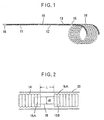
- FIG. 1 illustrates the construction of a medical wire which is an embodiment of the present invention.
- the medical wire in this embodiment basically comprises a conductive guide wire 10 made of a metal, a joint member 15 in the form of a short rod, which is connected at its proximal end to a distal end of the guide wire 10, and an implanted device 16 connected to the distal end of the joint member 15.
- the illustrated guide wire 10 comprises a proximal part 11 with a lubricating coating, a flexible part 12 adjacent thereto, and a distal X-ray impervious part 13 connected to the flexible part 12.
- the joint member 15 is connected to an end of the X-ray impervious part 13.
- the flexible part 12 and distal X-ray impervious part 13 of the guide wire 10 are constructed by, for example, closely winding a wire 0.01 to 0.2 mm in diameter at a pitch equal to its diameter on the peripheral surface of a core wire 0.03 to 2.0 mm in diameter to form a coil element of single, double or triple coil layers, for example.
- the guide wire 10 constructed by closely winding the wire on the peripheral surface of the core wire in a coiled form as described above is preferred since it combines sufficient flexibility with stiffness required for its insertion though it has a thin outer diameter.
- a wire of conductive metallic material such as stainless steel may be used for the guide wire 10.
- An X-ray impervious wire composed of a metal such as platinum, silver or tungsten may be used in the distal X-ray impervious part 13.
- the length of the guide wire 10 varies according to the intended application and could be 0.1 to 1.8 m, for example.
- the surface lubricating coating in the proximal part 11 of the guide wire 10 may be formed by any suitable material. It may be generally provided by covering with one of various resins, for example, a fluorocarbon resin or hydrophilic resin.
- the proximal part 11 is so constructed that at the most proximal end thereof, the wire is exposed to form a terminal part 18 through which a high-frequency current can be applied via suitable conductive members such as an electrical connector, plug and/or clip.
- suitable conductive members such as an electrical connector, plug and/or clip.
- suitable conductive members such as an electrical connector, plug and/or clip.
- about 1 to 3 cm will suffice for the length of this terminal part 18.
- the joint member 15 is melted and severed by heating with a high-frequency current, thereby detaching the implanted device 16 from the guide wire 10.
- the joint member 15 is composed of a rod of a swelling resin, which does not adversely affect the patient's body, and the outer diameter of which increases by at least 10% when brought into contact with water.
- a swelling resin which does not adversely affect the patient's body, and the outer diameter of which increases by at least 10% when brought into contact with water.
- poly(vinyl alcohol) or a vinyl alcohol copolymer having a polymerization degree of 500 to 4,000, preferably 1,500 to 2,500 is preferably used as such a swelling resin.
- the joint member 15 is fixedly connected to the guide wire 10 by further applying an adhesive in a state that its proximal part 15A has been inserted into the coiled distal part 14 of the guide wire 10.
- An example of the implanted device 16 used in the present invention includes a coil piece used as a thrombus-forming member as illustrated in FIG. 1.
- a double-coiled wire formed of a flexible material which is pliable, specifically, for example, a platinum alloy, should preferably be used in such a coil piece.
- the implanted device 16 formed of such a coil piece may carry or hold suitable substances.
- the implanted device 16 composed of a coil piece is fixedly connected to the joint member 15 by inserting the distal part 15B of the joint member 15 into the primary coil portion 16A of the implanted device 16 and further applying an adhesive thereto.
- the joint member 15 is composed of a rod of a swelling resin, the outer diameter of which increases by at least 10% when brought into contact with water. It is preferable that, as illustrated in FIG. 3, the outer diameter d1 of the joint member 15 in a swollen state is greater than any of the outer diameter d2 of the coiled distal part 14 of the guide wire 10 and the outer diameter d3 of the primary coil portion 16A of the implanted device 16.
- the joint member 15 should have an outer diameter d0 of 0.10 to 0.35 mm in an unswollen state and an outer diameter d1 of 0.25 to 1.00 mm in a swollen state by bringing it into contact with water. Its breaking strength in the swollen state is at least 100 g. The length of the joint member is 2 to 15 mm, preferably 5 to 10 mm. If a joint member having breaking strength in the swollen state smaller than 100 g is used, the joint member itself may possibly be broken in a pull-back operation.
- the outer diameter d2 of the coiled distal part 14 of the guide wire 10 is preferably 0.1 to 2.0 mm.
- a double-coiled wire which is produced by winding, for example, a wire having a diameter of 0.07 mm to form a primary coil having a diameter d3 of 0.1 to 1.0 mm and coiling the primary coil to form a secondary coil having a diameter of 2 to 40 mm, may preferably be used as the implanted device 16.
- the medical wire of the above-described construction is inserted into a patient's body to be treated by means of a suitable catheter 20.
- the catheter 20 is inserted in the patient's body 22 by a conventional method as illustrated in FIG. 5, so that the distal end thereof is situated at the intended site at which the implanted device 16 is to be deposited, or the site P of a cerebral aneurysm in the illustrated embodiment.
- Reference numeral 21 indicates the proximal operating part of the catheter 20.
- an ordinary catheter for example, a microcatheter can be used.
- catheter 20 used herein so long as it has an inner diameter greater than the outer diameter d2 of the guide wire 10 and the outer diameter d3 of the implanted device 16.
- a catheter having an inner diameter smaller than the outer diameter d1 of the joint member 15 swollen may also be used because the joint member 15 in a swollen state becomes somewhat pliable and deformable locally.
- the medical wire is inserted into the catheter 20 through the proximal operating part 21 with the implanted device 16 in the lead. Then, the coil piece forming the implanted device 16 moves along within the catheter 20 as a single coil with the secondary coil thereof stretched in an essentially straight line along the catheter 20.
- This inserting operation may be conducted under application of high-frequency voltage for measurement or detection between the guide wire 10 and a counter electrode 23 (see FIG. 5) for body earth provided on the optional skin surface of the patient's body by a high-frequency power source 24 connected to the terminal part 18 of the guide wire 10 and monitoring the magnitude of an impedance between the guide wire 10 and the counter electrode 23.
- the whole of the implanted device 16 of the medical wire is projected out of a distal opening of the catheter 20 so as to locate the joint member 15 at the distal opening.
- the impedance by the high-frequency voltage for measurement greatly reduces rapidly, thereby detecting the fact that the implanted device 16 has been deposited properly in the patient's body.
- a monopolar high-frequency current for detaching the implanted device is applied between the guide wire 10 and the counter electrode 23 by the high-frequency power source 24.
- the joint member 15 is heated at the distal end of the guide wire 10 with the high-frequency current with reaching a high temperature, whereby the joint member 15 is melted and severed. Therefore, the implanted device 16 is detached from the guide wire 10, whereby the implanted device 16 can be deposited in the cerebral aneurysm. The implanted device 16 returns to its original double-coiled form by its elasticity to serve as a thrombus-forming member.
- the high-frequency current is preferably such that the frequency and power are about 100 to 5,000 kHz and about 0.1 to 20 W, respectively, because it does not adversely affect the patient's body.
- the high-frequency voltage for measurement may be such that the frequency and voltage are about 100 to 5,000 kHz and about 0.1 to 3 V, respectively.
- the monopolar high-frequency current is applied to the joint member 15 through the guide wire 10 utilizing the conductivity of the guide wire 10, thereby heating the joint member 15 with certainty. Therefore, there is no need for lead wires extending to the joint member 15, thereby providing high operability, and no possibility that the lead wires could break. Accordingly, even when the implanted device 16 is pulled back for the purpose of changing or correcting the position of the implanted device deposited once, such an operation can be easily performed with certainty, securing high reliability.
- the joint member 15 is composed of a rod of a swelling resin, the outer diameter of which increases by at least 10% when brought into contact with water. Therefore, the outer diameter of the joint member 15 can be increased by, for example, dipping it in a saline solution prior to implementation of the medical wire, so that sufficiently great joint strength can be provided between the coiled distal part 14 of the guide wire 10 and the joint member 15, and between the primary coil portion 16A of the implanted device 16 and the joint member 15.
- the implanted device 16 can be inserted while maintaining proper pose of connection without changing the connection state of the guide wire 10 with the implanted device 16 through the joint member 15. Therefore, the implanted device 16 can be reliably deposited at the intended site in the patient's body. In addition, the implanted device 16 can also be pulled back surely by pulling back the guide wire 10 as needed.
- the guide wire 10 and the implanted device 16 are reliably prevented from coming into contact with each other upon moving along within the catheter 20 as apparent from FIG. 3. Accordingly, the joint member 15 is surely melted and severed by application of the high-frequency current.
- the outer diameter of the unswollen joint member 15 is as small as 0.10 to 0.35 mm, it can be easily connected to the guide wire 10 and implanted device 16, if they are those to be used generally.
- the barrier formed by the joint member 15 surely prevents the implanted device 16 from coming into direct contact with the distal end of the guide wire 10 within the catheter because the outer diameter of the joint member 15 increases by swelling as described above. Therefore, the impedance reducing phenomenon surely occurs when the distal end of the guide wire 10 is exposed out of the catheter, whereby the state that the implanted device has been deposited properly at the intended site in the patient's body can be detected with high reliability, while preventing wrong detection.
- a clearance L between the distal end of the coiled distal part 14 of the guide wire 10 and the proximal end of the primary coil portion 16A of the implanted device 16 connected through the joint member 15, is determined in a range of from 0.3 to 5.0 mm, the joint member 15 can be surely melted and severed without leaving a great residue with a high-frequency current of a frequency of about 100 to 5,000 kHz and power of about 0.1 to 20 W.
- the joint member 15 can be surely melted and severed by applying a high-frequency current for an extremely short period of within 1 to 3 seconds, for example. Therefore, stress imposed not only on a surgeon, but also on the patient can be greatly lightened. In addition, there is no possibility of forming metal ions as like in an electrolytic method, thus alleviating greatly the possibility that any contingencies may occur in the patient's body during the depositing operation.
- FIG. 6 illustrates another embodiment of the present invention.
- an electrically insulated coating 25 is provided on the peripheral surfaces of the flexible part 12 and distal X-ray impervious part 13 in the guide wire 10.
- This electrically insulated coating 25 can be formed by one of various polymers, for example, polyurethane, polyethylene, polypropylene, silicone resins and polyamide resins such as nylon.
- a hydrophilic polymer coat may be further provided on the coating of this resin.
- the implanted device 16 can be detached and deposited by applying a monopolar high-frequency current through the guide wire 10 as like in the above-described embodiment.
- the medical wire since almost the entire surface of the guide wire 10, with which the body tissue is brought into contact, is covered with the electrically insulated coating 25, the medical wire may be inserted into the patient's body without using any catheter.
- a columnar rod having a diameter of 0.20 mm and a length of 10 mm composed of a swelling vinyl alcohol copolymer having a polymerization degree of about 2,000 and a saponification degree of 98% or higher.
- a double-coiled wire constructed of a platinum alloy wire having a diameter of 0.05 mm, and having a primary coil diameter of 0.4 mm and a secondary coil diameter of 3 to 12 mm.
- a medical wire according to the present invention was produced by inserting a proximal part 15A of the joint member 15 into the coiled distal part 14 of the guide wire 10, which had an outer diameter of 0.4 mm and had been formed of only the wire to bond them with an adhesive, and inserting a distal part 15B of the joint member 15 into a proximal portion of the implanted device 16 to bond them with an adhesive, thereby connecting the implanted device 16 to the guide wire 10 through the joint member 15.
- the clearance L between the distal end of the coiled distal part 14 and the proximal end of the implanted device 16 was about 0.7 mm.
- the joint member 15 of this medical wire swelled and increased its outer diameter to about 0.5 mm when dipped for 3 minutes in physiological saline. This increment rate was about 150%, and its breaking strength in the swollen state was about 150 g.
- a catheter having an inner diameter of about 0.5 mm and an outer diameter of about 1 mm was arranged through a blood vessel from a femoral artery so that the distal end thereof was situated at a cerebral aneurysm.
- the medical wire as above was then inserted through the catheter.
- Applied to the guide wire 10 was high-frequency voltage for measurement of a frequency of 300 kHz and voltage of 1 V by a high-frequency power source connected to the terminal part 18 situated at the proximal end of the guide wire 10.
- An impedance reducing phenomenon was detected at the time the distal end of the guide wire 10 was situated at the distal opening of the catheter.
- the impedance between the proximal end of the guide wire 10 and a counter electrode 23 for body earth which was about 2 k ⁇ during the inserting operation, rapidly reduced to about 300 ⁇ .
- the guide wire 10 may be composed of a single wire or a bundle of wires, or may be a wire composed of multiple wire segments of suitable lengths connected in series.
- various kinds of implanted devices 16 may be employed. Specifically, thrombus-forming members in the form of a coil piece or forms other than the coil piece, such as capsules containing a drug therein, which are left in the patient's body to gradually release the drug, embolizing members for occluding tubular organs, such as balloons, as well as suitable devices which perform a medical function or medically auxiliary function while implanted.
- the joint member through which the implanted device is connected to the guide wire is composed of a rod of a resin having specific swelling characteristics. Therefore, the joint strength of the joint member with the guide wire and the implanted device can be made sufficiently great utilizing the swelling of the joint member to increase its outer diameter by absorbing water upon bring the joint member into contact with, for example, physiological saline before insertion into a patient's body, or upon coming into contact with blood or other humors in the course of insertion into the patient's body.
- joints of the guide wire and implanted device with the joint member are in the form of a coil, sufficiently great joint strength can be surely obtained by inserting both end parts of the joint member into the respective coils to connect them.
- the joint member undergoes neither bending nor deformation, and moreover the pushing force applied to the guide wire is reliably transmitted to the implanted device through the joint member.
- the implanted device can be inserted while maintaining proper pose of connection without changing the connection state of the guide wire with the implanted device through the joint member. Therefore, the implanted device can be reliably deposited at the intended site in the patient's body and also pulled back surely.
- the joint member of the medical wire implemented for the patient's body swells to contain a moderate amount of water, and hence can be successfully melted and severed by applying a high-frequency current.
- the outer diameter of the joint member increases by swelling, the electrical insulation between the guide wire and the implanted device can be suitably ensured, both guide wire and implanted device can be reliably prevented from coming into contact with each other during use, and the implanted device can be surely detached from the guide wire by applying a high-frequency current to the joint member.
Landscapes
- Health & Medical Sciences (AREA)
- Life Sciences & Earth Sciences (AREA)
- Surgery (AREA)
- Engineering & Computer Science (AREA)
- Biomedical Technology (AREA)
- Veterinary Medicine (AREA)
- Public Health (AREA)
- Heart & Thoracic Surgery (AREA)
- Animal Behavior & Ethology (AREA)
- General Health & Medical Sciences (AREA)
- Vascular Medicine (AREA)
- Nuclear Medicine, Radiotherapy & Molecular Imaging (AREA)
- Reproductive Health (AREA)
- Medical Informatics (AREA)
- Molecular Biology (AREA)
- Oral & Maxillofacial Surgery (AREA)
- Transplantation (AREA)
- Cardiology (AREA)
- Biophysics (AREA)
- Pulmonology (AREA)
- Anesthesiology (AREA)
- Hematology (AREA)
- Media Introduction/Drainage Providing Device (AREA)
- Surgical Instruments (AREA)
Claims (8)
- Fil médical ayant un dispositif implanté (16), dans lequel le dispositif implanté (16) est connecté à une extrémité distale d'un fil guide conducteur (10) par un élément de raccord (15), et l'élément de raccord (15) est adapté pour être chauffé en appliquant un courant de haute fréquence dans le fil guide (10), moyennant quoi l'élément de raccord (15) est adapté pour être fondu et sectionné de manière à détacher le dispositif implanté (16) du fil guide (10), dans lequel l'élément de raccord (15) est composé d'une tige formée d'une résine gonflante, dont le diamètre extérieur augmente d'au moins 10 % lorsqu'elle est mise en contact avec de l'eau, et dans lequel l'élément de raccord (15) a une résistance à la rupture d'au moins 100 grammes dans un état gonflé.
- Fil médical selon la revendication 1, dans lequel l'élément de raccord (15) est connecté au fil guide (10) en insérant sa partie proximale (11) dans une partie distale en spirale (14) du fil guide (10) et connecté au dispositif implanté (16) en insérant sa partie distale dans une partie de spirale (16A) formant le dispositif implanté (16).
- Fil médical selon la revendication 2, dans lequel le diamètre extérieur de l'élément de raccord (15) dans un état gonflé est supérieur à l'un quelconque des diamètres extérieurs de la partie distale en spirale (14) du fil guide (10) et de la partie de spirale (16) formant le dispositif implanté (16).
- Fil médical selon la revendication 1, dans lequel l'élément de raccord (15) a un diamètre extérieur de 0,10 à 0,35 mm dans un état non gonflé.
- Fil médical selon la revendication 4, dans lequel l'élément de raccord (15) a un diamètre extérieur de 0,25 à 1,00 mm dans un état gonflé.
- Fil médical selon la revendication 1, dans lequel l'élément de raccord (15) est formé par du poly(alcool vinylique) ou un copolymère d'alcool vinylique.
- Fil médical selon la revendication 1, dans lequel un espace entre l'extrémité distale du fil guide (10) et l'extrémité proximale du dispositif implanté (16) connectée par l'élément de raccord (15) au fil guide, est de 0,3 à 5,0 mm.
- Fil médical selon la revendication 1, dans lequel l'élément de raccord (15) est adapté pour être fondu et sectionné en appliquant un courant de haute fréquence d'une fréquence de 100 à 5000 kHz et d'une puissance de 0,1 à 20 W entre le fil guide (10) et une contre-électrode, l'électrode ne faisant pas partie du fil médical.
Applications Claiming Priority (3)
| Application Number | Priority Date | Filing Date | Title |
|---|---|---|---|
| JP250576/96 | 1996-09-20 | ||
| JP25057696A JP3754145B2 (ja) | 1996-09-20 | 1996-09-20 | 生体内留置部材を有する医療用ワイヤー |
| JP25057696 | 1996-09-20 |
Publications (3)
| Publication Number | Publication Date |
|---|---|
| EP0830873A2 EP0830873A2 (fr) | 1998-03-25 |
| EP0830873A3 EP0830873A3 (fr) | 1998-04-15 |
| EP0830873B1 true EP0830873B1 (fr) | 2004-04-21 |
Family
ID=17209951
Family Applications (1)
| Application Number | Title | Priority Date | Filing Date |
|---|---|---|---|
| EP97115737A Expired - Lifetime EP0830873B1 (fr) | 1996-09-20 | 1997-09-10 | Fil médical en connexion avec un dispositif implanté |
Country Status (4)
| Country | Link |
|---|---|
| US (1) | US5846210A (fr) |
| EP (1) | EP0830873B1 (fr) |
| JP (1) | JP3754145B2 (fr) |
| DE (1) | DE69728725T2 (fr) |
Cited By (10)
| Publication number | Priority date | Publication date | Assignee | Title |
|---|---|---|---|---|
| US8192480B2 (en) | 2007-12-21 | 2012-06-05 | Microvention, Inc. | System and method of detecting implant detachment |
| US8864790B2 (en) | 2006-04-17 | 2014-10-21 | Covidien Lp | System and method for mechanically positioning intravascular implants |
| US8932317B2 (en) | 1999-06-02 | 2015-01-13 | Microvention, Inc. | Intracorporeal occlusive device and method |
| US9011480B2 (en) | 2012-01-20 | 2015-04-21 | Covidien Lp | Aneurysm treatment coils |
| US9050095B2 (en) | 2004-09-22 | 2015-06-09 | Covidien Lp | Medical implant |
| US9198665B2 (en) | 2004-09-22 | 2015-12-01 | Covidien Lp | Micro-spiral implantation device |
| US9242070B2 (en) | 2007-12-21 | 2016-01-26 | MicronVention, Inc. | System and method for locating detachment zone of a detachable implant |
| US9289215B2 (en) | 2007-03-13 | 2016-03-22 | Covidien Lp | Implant including a coil and a stretch-resistant member |
| US9561125B2 (en) | 2010-04-14 | 2017-02-07 | Microvention, Inc. | Implant delivery device |
| US9579104B2 (en) | 2011-11-30 | 2017-02-28 | Covidien Lp | Positioning and detaching implants |
Families Citing this family (51)
| Publication number | Priority date | Publication date | Assignee | Title |
|---|---|---|---|---|
| US6689121B1 (en) | 1998-09-24 | 2004-02-10 | C. R. Bard, Inc. | Systems and methods for treating ischemia |
| WO2000018331A2 (fr) * | 1998-09-29 | 2000-04-06 | C. R. Bard, Inc. | Systemes d'administration de medicaments |
| US6248112B1 (en) | 1998-09-30 | 2001-06-19 | C. R. Bard, Inc. | Implant delivery system |
| US6458092B1 (en) | 1998-09-30 | 2002-10-01 | C. R. Bard, Inc. | Vascular inducing implants |
| US6432126B1 (en) | 1998-09-30 | 2002-08-13 | C.R. Bard, Inc. | Flexible vascular inducing implants |
| US6251079B1 (en) | 1998-09-30 | 2001-06-26 | C. R. Bard, Inc. | Transthoracic drug delivery device |
| FR2785172B1 (fr) * | 1998-11-02 | 2000-12-29 | Assist Publ Hopitaux De Paris | Spire metallique biocompatible et dispositifs de pose de spires d'occlusion vasculaire electrosecables a longueur ajustable |
| US6692520B1 (en) | 1998-12-15 | 2004-02-17 | C. R. Bard, Inc. | Systems and methods for imbedded intramuscular implants |
| JP4191301B2 (ja) * | 1999-02-10 | 2008-12-03 | 株式会社カネカメディックス | 生体内留置部材を有する医療用ワイヤー |
| US6620170B1 (en) | 1999-04-26 | 2003-09-16 | C. R. Bard, Inc. | Devices and methods for treating ischemia by creating a fibrin plug |
| US6986784B1 (en) | 1999-05-14 | 2006-01-17 | C. R. Bard, Inc. | Implant anchor systems |
| US6719805B1 (en) | 1999-06-09 | 2004-04-13 | C. R. Bard, Inc. | Devices and methods for treating tissue |
| US6277082B1 (en) | 1999-07-22 | 2001-08-21 | C. R. Bard, Inc. | Ischemia detection system |
| US6629987B1 (en) | 1999-07-30 | 2003-10-07 | C. R. Bard, Inc. | Catheter positioning systems |
| US6855160B1 (en) | 1999-08-04 | 2005-02-15 | C. R. Bard, Inc. | Implant and agent delivery device |
| US7232421B1 (en) | 2000-05-12 | 2007-06-19 | C. R. Bard, Inc. | Agent delivery systems |
| US7204847B1 (en) | 2000-07-28 | 2007-04-17 | C. R. Bard, Inc. | Implant anchor systems |
| US6743251B1 (en) * | 2000-11-15 | 2004-06-01 | Scimed Life Systems, Inc. | Implantable devices with polymeric detachment junction |
| US8298160B2 (en) | 2001-03-16 | 2012-10-30 | Ev3 Inc. | Wire convertible from over-the-wire length to rapid exchange length |
| DE10155191A1 (de) * | 2001-11-12 | 2003-05-22 | Dendron Gmbh | Medizinisches Implantat |
| US6989024B2 (en) * | 2002-02-28 | 2006-01-24 | Counter Clockwise, Inc. | Guidewire loaded stent for delivery through a catheter |
| FI112913B (fi) * | 2002-06-27 | 2004-02-13 | Mega Elektroniikka Oy | Menetelmä kehon lihasten toiminnan mittaamiseksi ja asuste menetelmän soveltamiseksi |
| WO2004062510A1 (fr) * | 2003-01-10 | 2004-07-29 | Kaneka Corporation | Enroulement a demeure in vivo formant embole |
| WO2004089207A1 (fr) * | 2003-04-08 | 2004-10-21 | Pp-Technologies Ag | Procede de mesure de pressions sur la base de courants de fuite |
| AU2004241111B2 (en) | 2003-05-15 | 2010-05-27 | Dsm Ip Assets B.V | Manufacture and use of implantable reticulated elastomeric matrices |
| US20050021023A1 (en) * | 2003-07-23 | 2005-01-27 | Scimed Life Systems, Inc. | System and method for electrically determining position and detachment of an implantable device |
| US7763077B2 (en) | 2003-12-24 | 2010-07-27 | Biomerix Corporation | Repair of spinal annular defects and annulo-nucleoplasty regeneration |
| CN104523313B (zh) | 2004-08-25 | 2018-05-18 | 微仙美国有限公司 | 植入物装置递送系统 |
| US8021371B2 (en) | 2004-10-29 | 2011-09-20 | Kaneka Corporation | Medical wire |
| CN101048107A (zh) * | 2004-10-29 | 2007-10-03 | 株式会社钟化 | 医疗用线 |
| JP4724827B2 (ja) * | 2005-03-24 | 2011-07-13 | 国立大学法人山口大学 | 攪拌処理装置及びカテーテル |
| WO2006126474A1 (fr) * | 2005-05-24 | 2006-11-30 | Kaneka Corporation | Fil medical |
| US8998926B2 (en) * | 2006-04-06 | 2015-04-07 | DePuy Synthes Products, LLC | Heat detachable coil |
| US8777979B2 (en) | 2006-04-17 | 2014-07-15 | Covidien Lp | System and method for mechanically positioning intravascular implants |
| KR20100015521A (ko) | 2007-03-13 | 2010-02-12 | 마이크로 테라퓨틱스 인코포레이티드 | 임플란트, 맨드릴, 및 임플란트 형성방법 |
| US20080255654A1 (en) * | 2007-03-22 | 2008-10-16 | Bay Street Medical | System for delivering a stent |
| US20080300667A1 (en) * | 2007-05-31 | 2008-12-04 | Bay Street Medical | System for delivering a stent |
| EP2859854B1 (fr) | 2008-09-09 | 2020-01-15 | Boston Scientific Scimed, Inc. | Mécanisme de détachement composite |
| GB0902339D0 (en) * | 2009-02-12 | 2009-04-01 | St Georges Healthcare Nhs Trus | Percutaneous guidewire |
| US9687245B2 (en) | 2012-03-23 | 2017-06-27 | Covidien Lp | Occlusive devices and methods of use |
| US20140114255A1 (en) * | 2012-10-19 | 2014-04-24 | Cook Medical Technologies Llc | Self-coiling stylet needle device |
| WO2014081942A1 (fr) * | 2012-11-21 | 2014-05-30 | Concert Medical, Llc | Fil-guide préformé |
| CN103284773B (zh) * | 2013-05-31 | 2016-04-27 | 威海维心医疗设备有限公司 | 热熔解脱弹簧圈系统 |
| WO2015034831A1 (fr) | 2013-09-03 | 2015-03-12 | Jianlu Ma | Mécanismes de détachement pour dispositifs implantables |
| CA2934555C (fr) | 2013-12-20 | 2020-07-07 | Microvention, Inc. | Systeme de mise en place de dispositif |
| WO2015157768A1 (fr) | 2014-04-11 | 2015-10-15 | Microvention, Inc. | Système de mise en place d'implant |
| US9713475B2 (en) | 2014-04-18 | 2017-07-25 | Covidien Lp | Embolic medical devices |
| EP3662846A4 (fr) | 2017-07-31 | 2021-08-04 | Kaneka Corporation | Instrument à demeure in vivo, système de pose d'instrument à demeure in vivo et procédé de fabrication d'instrument à demeure in vivo |
| CN110960280B (zh) * | 2018-09-30 | 2025-08-01 | 微创神通医疗科技(上海)有限公司 | 电解脱机构以及电解脱装置 |
| US12114863B2 (en) | 2018-12-05 | 2024-10-15 | Microvention, Inc. | Implant delivery system |
| WO2025085811A1 (fr) * | 2023-10-19 | 2025-04-24 | Draht Medical, Inc. | Fil-guide |
Citations (1)
| Publication number | Priority date | Publication date | Assignee | Title |
|---|---|---|---|---|
| JPH07265431A (ja) * | 1994-03-31 | 1995-10-17 | Kaneka Medics:Kk | 生体内留置部材を有する医療用ワイヤー |
Family Cites Families (11)
| Publication number | Priority date | Publication date | Assignee | Title |
|---|---|---|---|---|
| JPS6030225B2 (ja) * | 1979-09-14 | 1985-07-15 | 株式会社クラレ | 先端に生体内留置部材を有する誘導子 |
| US4346712A (en) * | 1979-04-06 | 1982-08-31 | Kuraray Company, Ltd. | Releasable balloon catheter |
| JPH0284964A (ja) * | 1988-03-18 | 1990-03-26 | Tokai Rika Co Ltd | バルーンカテーテル用高周波電源装置 |
| US5569245A (en) * | 1990-03-13 | 1996-10-29 | The Regents Of The University Of California | Detachable endovascular occlusion device activated by alternating electric current |
| US5122136A (en) * | 1990-03-13 | 1992-06-16 | The Regents Of The University Of California | Endovascular electrolytically detachable guidewire tip for the electroformation of thrombus in arteries, veins, aneurysms, vascular malformations and arteriovenous fistulas |
| US5258042A (en) * | 1991-12-16 | 1993-11-02 | Henry Ford Health System | Intravascular hydrogel implant |
| IL106946A0 (en) * | 1992-09-22 | 1993-12-28 | Target Therapeutics Inc | Detachable embolic coil assembly |
| JPH06246004A (ja) * | 1993-02-26 | 1994-09-06 | Raifu Technol Kenkyusho | カテーテル |
| US5498227A (en) * | 1993-09-15 | 1996-03-12 | Mawad; Michel E. | Retrievable, shielded radiotherapy implant |
| US5423829A (en) * | 1993-11-03 | 1995-06-13 | Target Therapeutics, Inc. | Electrolytically severable joint for endovascular embolic devices |
| JPH07284534A (ja) * | 1994-04-15 | 1995-10-31 | Kato Hatsujo Kaisha Ltd | 管状器官の治療具 |
-
1996
- 1996-09-20 JP JP25057696A patent/JP3754145B2/ja not_active Expired - Lifetime
-
1997
- 1997-09-08 US US08/925,611 patent/US5846210A/en not_active Expired - Lifetime
- 1997-09-10 DE DE69728725T patent/DE69728725T2/de not_active Expired - Lifetime
- 1997-09-10 EP EP97115737A patent/EP0830873B1/fr not_active Expired - Lifetime
Patent Citations (2)
| Publication number | Priority date | Publication date | Assignee | Title |
|---|---|---|---|---|
| JPH07265431A (ja) * | 1994-03-31 | 1995-10-17 | Kaneka Medics:Kk | 生体内留置部材を有する医療用ワイヤー |
| US5759161A (en) * | 1994-03-31 | 1998-06-02 | Kaneka Medix Corporation | Medical wire and method for leaving implanted devices |
Cited By (17)
| Publication number | Priority date | Publication date | Assignee | Title |
|---|---|---|---|---|
| US9788840B2 (en) | 1999-06-02 | 2017-10-17 | Michael P. Marks | Intracorporeal occlusive device and method |
| US8932317B2 (en) | 1999-06-02 | 2015-01-13 | Microvention, Inc. | Intracorporeal occlusive device and method |
| US9526505B2 (en) | 1999-06-02 | 2016-12-27 | Microvention, Inc. | Intracorporeal occlusive device and method |
| US9198665B2 (en) | 2004-09-22 | 2015-12-01 | Covidien Lp | Micro-spiral implantation device |
| US9050095B2 (en) | 2004-09-22 | 2015-06-09 | Covidien Lp | Medical implant |
| US8864790B2 (en) | 2006-04-17 | 2014-10-21 | Covidien Lp | System and method for mechanically positioning intravascular implants |
| US9289215B2 (en) | 2007-03-13 | 2016-03-22 | Covidien Lp | Implant including a coil and a stretch-resistant member |
| US9242070B2 (en) | 2007-12-21 | 2016-01-26 | MicronVention, Inc. | System and method for locating detachment zone of a detachable implant |
| US8192480B2 (en) | 2007-12-21 | 2012-06-05 | Microvention, Inc. | System and method of detecting implant detachment |
| US8460332B2 (en) | 2007-12-21 | 2013-06-11 | Microvention, Inc. | System and method of detecting implant detachment |
| US10299755B2 (en) | 2007-12-21 | 2019-05-28 | Microvention, Inc. | System and method for locating detachment zone of a detachable implant |
| US9561125B2 (en) | 2010-04-14 | 2017-02-07 | Microvention, Inc. | Implant delivery device |
| US10517604B2 (en) | 2010-04-14 | 2019-12-31 | Microvention, Inc. | Implant delivery device |
| US11357513B2 (en) | 2010-04-14 | 2022-06-14 | Microvention, Inc. | Implant delivery device |
| US12114864B2 (en) | 2010-04-14 | 2024-10-15 | Microvention, Inc. | Implant delivery device |
| US9579104B2 (en) | 2011-11-30 | 2017-02-28 | Covidien Lp | Positioning and detaching implants |
| US9011480B2 (en) | 2012-01-20 | 2015-04-21 | Covidien Lp | Aneurysm treatment coils |
Also Published As
| Publication number | Publication date |
|---|---|
| DE69728725T2 (de) | 2004-08-19 |
| DE69728725D1 (de) | 2004-05-27 |
| EP0830873A3 (fr) | 1998-04-15 |
| JP3754145B2 (ja) | 2006-03-08 |
| JPH1094542A (ja) | 1998-04-14 |
| US5846210A (en) | 1998-12-08 |
| EP0830873A2 (fr) | 1998-03-25 |
Similar Documents
| Publication | Publication Date | Title |
|---|---|---|
| US5846210A (en) | Medical wire having implanted device and method for using the same | |
| US5759161A (en) | Medical wire and method for leaving implanted devices | |
| US6159206A (en) | Medical implement for depositing implanted device and method of depositing implanted device | |
| US6743251B1 (en) | Implantable devices with polymeric detachment junction | |
| JP5677955B2 (ja) | 複合脱離機構 | |
| JP2610412B2 (ja) | 血管内塞栓用具のための電気分解的分離可能な接合部 | |
| CA2175100C (fr) | Catheter pour l'introduction d'un implant separable par electrolyse | |
| CA2166142C (fr) | Lien sans soudure, pouvant etre scinde par electrolyse, pour dispositifs amovibles inseres dans l'organisme d'un mammifere | |
| US6533801B2 (en) | Vaso-occlusive member assembly with multiple detaching points | |
| EP0824010B2 (fr) | Bobine d'embolisation | |
| EP2997911B1 (fr) | Système de détachement de dispositif d'occlusion vasculaire avec fil central conique et détachement activé par élément chauffant | |
| WO2018005113A1 (fr) | Séparation électrolytique présentant une connexion électrique fluidique | |
| GB2115289A (en) | Releasable balloon catheter | |
| JP2022511996A (ja) | 電解分離機構および電気的分離デバイス | |
| WO2009058360A1 (fr) | Mécanismes de désaccouplement dégradables pour dispositifs implantables | |
| AU6349499A (en) | Vascular occlusion device with adjustable length | |
| JP4191301B2 (ja) | 生体内留置部材を有する医療用ワイヤー | |
| AU2021227736A1 (en) | Endovascular prosthesis delivery system |
Legal Events
| Date | Code | Title | Description |
|---|---|---|---|
| PUAI | Public reference made under article 153(3) epc to a published international application that has entered the european phase |
Free format text: ORIGINAL CODE: 0009012 |
|
| PUAL | Search report despatched |
Free format text: ORIGINAL CODE: 0009013 |
|
| AK | Designated contracting states |
Kind code of ref document: A2 Designated state(s): DE FR GB |
|
| AK | Designated contracting states |
Kind code of ref document: A3 Designated state(s): AT BE CH DE DK ES FI FR GB GR IE IT LI LU MC NL PT SE |
|
| 17P | Request for examination filed |
Effective date: 19980529 |
|
| AKX | Designation fees paid |
Free format text: DE FR GB |
|
| RBV | Designated contracting states (corrected) |
Designated state(s): DE FR GB |
|
| 17Q | First examination report despatched |
Effective date: 20020502 |
|
| GRAP | Despatch of communication of intention to grant a patent |
Free format text: ORIGINAL CODE: EPIDOSNIGR1 |
|
| RTI1 | Title (correction) |
Free format text: MEDICAL WIRE CONNECTED TO AN IMPLANTED DEVICE |
|
| RTI1 | Title (correction) |
Free format text: MEDICAL WIRE CONNECTED TO AN IMPLANTED DEVICE |
|
| GRAS | Grant fee paid |
Free format text: ORIGINAL CODE: EPIDOSNIGR3 |
|
| GRAA | (expected) grant |
Free format text: ORIGINAL CODE: 0009210 |
|
| AK | Designated contracting states |
Kind code of ref document: B1 Designated state(s): DE FR GB |
|
| REG | Reference to a national code |
Ref country code: GB Ref legal event code: FG4D |
|
| RIC1 | Information provided on ipc code assigned before grant |
Ipc: 7A 61B 17/12 A |
|
| REF | Corresponds to: |
Ref document number: 69728725 Country of ref document: DE Date of ref document: 20040527 Kind code of ref document: P |
|
| ET | Fr: translation filed | ||
| PLBE | No opposition filed within time limit |
Free format text: ORIGINAL CODE: 0009261 |
|
| STAA | Information on the status of an ep patent application or granted ep patent |
Free format text: STATUS: NO OPPOSITION FILED WITHIN TIME LIMIT |
|
| 26N | No opposition filed |
Effective date: 20050124 |
|
| REG | Reference to a national code |
Ref country code: FR Ref legal event code: CA Effective date: 20130301 |
|
| REG | Reference to a national code |
Ref country code: FR Ref legal event code: PLFP Year of fee payment: 20 |
|
| PGFP | Annual fee paid to national office [announced via postgrant information from national office to epo] |
Ref country code: GB Payment date: 20160926 Year of fee payment: 20 |
|
| PGFP | Annual fee paid to national office [announced via postgrant information from national office to epo] |
Ref country code: FR Payment date: 20160923 Year of fee payment: 20 |
|
| PGFP | Annual fee paid to national office [announced via postgrant information from national office to epo] |
Ref country code: DE Payment date: 20160928 Year of fee payment: 20 |
|
| REG | Reference to a national code |
Ref country code: DE Ref legal event code: R071 Ref document number: 69728725 Country of ref document: DE |
|
| REG | Reference to a national code |
Ref country code: GB Ref legal event code: PE20 Expiry date: 20170909 |
|
| PG25 | Lapsed in a contracting state [announced via postgrant information from national office to epo] |
Ref country code: GB Free format text: LAPSE BECAUSE OF EXPIRATION OF PROTECTION Effective date: 20170909 |