EP0830926A2 - Conteneur pour béton - Google Patents
Conteneur pour béton Download PDFInfo
- Publication number
- EP0830926A2 EP0830926A2 EP97112664A EP97112664A EP0830926A2 EP 0830926 A2 EP0830926 A2 EP 0830926A2 EP 97112664 A EP97112664 A EP 97112664A EP 97112664 A EP97112664 A EP 97112664A EP 0830926 A2 EP0830926 A2 EP 0830926A2
- Authority
- EP
- European Patent Office
- Prior art keywords
- concrete
- spar
- concrete container
- flexible tube
- container
- Prior art date
- Legal status (The legal status is an assumption and is not a legal conclusion. Google has not performed a legal analysis and makes no representation as to the accuracy of the status listed.)
- Granted
Links
Images


Classifications
-
- B—PERFORMING OPERATIONS; TRANSPORTING
- B28—WORKING CEMENT, CLAY, OR STONE
- B28C—PREPARING CLAY; PRODUCING MIXTURES CONTAINING CLAY OR CEMENTITIOUS MATERIAL, e.g. PLASTER
- B28C7/00—Controlling the operation of apparatus for producing mixtures of clay or cement with other substances; Supplying or proportioning the ingredients for mixing clay or cement with other substances; Discharging the mixture
- B28C7/0046—Storage or weighing apparatus for supplying ingredients
- B28C7/0053—Storage containers, e.g. hoppers, silos, bins
- B28C7/0076—Parts or details thereof, e.g. opening, closing or unloading means
Definitions
- the invention relates to a concrete container for placing concrete in Formwork, consisting of a container open at the top with a post bottom tapering bottom with an outlet opening and an adjoining flexible pipe, in particular a hose for distributing the concrete, wherein the container and / or a support frame receiving it suspending means has, with which the concrete container can be attached to a hoist, wherein below the outlet opening of the concrete container is essentially horizontal horizontal spar that can be moved transversely to the free-hanging flexible tube is, the displacement of which is at least approximately the diameter of the flexible Corresponds to the tube and the one below its outlet opening crosses the area and thereby the cross section of the flexible Rohres tapered.
- formwork is filled with concrete during construction of a building used concrete containers.
- this concrete container has an outlet opening with a slide flap that can be actuated by means of a pivoted lever.
- the one on a hoist attached concrete container is placed on the side of a concrete transporter and loaded with concrete via a filling channel. This lifts the concrete container filled in this way Hoist and carry it to the place where the concrete is to be inserted into the formwork is.
- the man standing by at this point operates the lever to open it the slide valve, and the concrete slips due to its own weight through the outlet opening into the formwork.
- a contraction valve with a controllable Contains valve body made of an elastic material.
- the mouthpiece owns two pipes of approximately the same size running in a common longitudinal direction and a hose connecting them from an elastically deformable material, which can be pressed together between the two tubes.
- An outer tube is with the two inner tubes through axially extending, funnel-shaped Parts sealed together so that an annular space is created, which can be connected to a pressure medium source.
- a mouthpiece This type has a considerable length and is therefore not suitable for concrete containers suitable, for precisely those reasons that are already above and introductory are discussed.
- closure known from FR 2 359 262 A1 should also be mentioned.
- tooth segments are arranged in pairs below the outlet opening of the container and spaced-apart tooth segments are provided, which together comb and one of which is pivotable by means of a lever.
- Several spars are arranged between the tooth segments forming a pair, whose centers lie on a spiral line. Runs between these spars the flexible hose fixed at the outlet opening, which by swiveling the tooth segments can be squeezed together.
- This facility is structurally complex and bulky, apart from the fact that toothed segments no suitable components for the rough operation provided here represent.
- the invention provides that the two ends of the spar, whose length is at least the diameter corresponds to the flexible pipe, using handlebars, ropes or chains on the concrete container are suspended and that articulated springs at the two ends of the Holmes are, whose other ends on the support frame of the concrete container are fixed and the tension springs are tensioned when the spar is to the side of the outflow opening in its position releasing the flexible pipe or its cross section is located and on the spar, preferably in the central area Actuator is articulated, on the other hand with the support frame of the concrete container is connected and with which the spar is movable against the force of the tension spring is.
- Advantageous embodiments of the invention are in the subclaims captured.
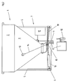
- the concrete container 1 has an upper, cylindrical section 2 and one at the bottom adjoining, tapered section 3, which down into a Outlet opening 4 opens.
- Vertical struts 5 with their lower ends an open ring 6 are fixed, form a support frame 7, which the concrete container 1 picks up or with which the concrete container 1 is firmly connected.
- a flexible tube 8 preferably a rubber elastic Hose attached, the length of which can be several meters and on the lower mouth opening 9, a switch console 10 is arranged, which has a Line 11 is connected to a drive unit 12, which in turn from Support frame 7 is worn.
- This Spar 15 consists of a shaft 16 on which freely rotatable rollers 17 are mounted are.
- This spar 15 is located somewhat below the outlet opening 4, expediently in the plane of the open ring 6.
- a Actuator 18 connected, the other end connected to the open ring is.
- This actuator 18 can be designed as a piston-cylinder unit or as a purely mechanical component (screw mechanism, threaded rod, gear mechanism or the like.).
- Tension springs 19 are also located at the two ends of the spar 15 arranged, with their respective other ends facing each other Sections of the open ring 6 are attached.
- FIG. 1 now shows the position of the spar 15 in which the cross section of the hose 8 is released.
- the tension springs 19 are tensioned and the actuator 18, the is designed as a piston-cylinder unit, is acted upon. Should be for loading of the concrete container 1 or for transporting the hose 8 is closed are, the actuator 18 is relieved, and by the force of the tensioned Tension springs 19, the spar 15 is pulled to the right (Fig. 1), the hose 8 deformed in the manner shown in FIG. 2, its cross-section tapers and is thus closed.
- the spar 15 (FIG. 2) assumes this position when the concrete container 1 is filled or transported using a hoist. Hold the force of the springs 19 the spar 15 in its closed position, because during filling or transport the concrete container has no energy supply. Should the concrete container 1 are emptied, the actuator 18 is acted upon and pulls the spar 15 against the force of the springs 19 to the left (Fig. 1), so that the Hose 8 hangs freely at the outlet opening 4, its cross section entirely is open and the concrete in the container is down through the hose can flow out. The tension springs 19 are in turn biased. The rollers 17 on the spar 15 prevent abrasion on the hose 8.
- the handlebars 14 hold the Spar 15 in its operating position and prevent sagging of the articulated Systems and also relieve the closed hose 8 from that lying on it Concrete weight. In addition, the spar 15 moves on an arc Path between closed and open position, what the folding and closing the hose 8 favors.
- the drive unit 12 via which the actuator 18 is acted upon, can be supplied with electrical energy, either via supply cables or by means of batteries and accumulators. Other forms of energy, for example Compressed air can be used here. Instead of actuating a switch, the drive unit can 12 can also be controlled by radio.
- the locking mechanism is essentially maintenance-free and protected against contamination by concrete. Because the closure is constructed that no moving parts can come into contact with the fresh concrete relatively thin-flowing concrete can be distributed without dripping concrete slurry. If a removable switch is mounted at the lower end of the hose 8 or the concrete container is controlled by radio, the hose can be 8 or lower end in wall formwork or climbing formwork systems.
- the mechanical tension springs 19 ensure that the hose 8 is closed is when no external energy supply is available. Basically is it is possible to use other components instead of such mechanical tension springs to be used, which have a comparable effect or which may result from external energy consumption are actuated. Instead of a just trained one Holmes, as shown and described above, this spar can also be arcuate be designed or loop or ring-shaped. The one for its postponement Actuators provided below the outlet opening 4 are then correspondingly articulated to this spar designed in this way Loop or this ring is then slightly larger than the outside diameter of the Hose 8, so that the hose through this loop or through this ring can sag freely.
Landscapes
- Chemical & Material Sciences (AREA)
- Dispersion Chemistry (AREA)
- On-Site Construction Work That Accompanies The Preparation And Application Of Concrete (AREA)
- Moulds, Cores, Or Mandrels (AREA)
- Graft Or Block Polymers (AREA)
- Centrifugal Separators (AREA)
Priority Applications (1)
| Application Number | Priority Date | Filing Date | Title |
|---|---|---|---|
| AT97112664T ATE233155T1 (de) | 1996-09-23 | 1997-07-24 | Betoncontainer |
Applications Claiming Priority (3)
| Application Number | Priority Date | Filing Date | Title |
|---|---|---|---|
| AT1682/96 | 1996-09-23 | ||
| AT168296 | 1996-09-23 | ||
| AT168296 | 1996-09-23 |
Publications (3)
| Publication Number | Publication Date |
|---|---|
| EP0830926A2 true EP0830926A2 (fr) | 1998-03-25 |
| EP0830926A3 EP0830926A3 (fr) | 1999-08-11 |
| EP0830926B1 EP0830926B1 (fr) | 2003-02-26 |
Family
ID=3518718
Family Applications (1)
| Application Number | Title | Priority Date | Filing Date |
|---|---|---|---|
| EP97112664A Expired - Lifetime EP0830926B1 (fr) | 1996-09-23 | 1997-07-24 | Conteneur pour béton |
Country Status (5)
| Country | Link |
|---|---|
| US (1) | US5956908A (fr) |
| EP (1) | EP0830926B1 (fr) |
| JP (1) | JPH10159339A (fr) |
| AT (1) | ATE233155T1 (fr) |
| DE (1) | DE59709376D1 (fr) |
Cited By (1)
| Publication number | Priority date | Publication date | Assignee | Title |
|---|---|---|---|---|
| EP2397297A3 (fr) * | 2010-06-15 | 2014-03-26 | Elematic Oy Ab | Procédé et appareil pour mouler un produit en béton |
Families Citing this family (7)
| Publication number | Priority date | Publication date | Assignee | Title |
|---|---|---|---|---|
| CN1311168C (zh) * | 2001-12-31 | 2007-04-18 | 中国水利水电第四工程局 | 液压蓄能吊罐卸料系统启闭自动控制方法 |
| US8591146B2 (en) * | 2009-04-20 | 2013-11-26 | Volvo Construction Equipment Ab | Integrated paving system and method |
| EP2664552B1 (fr) * | 2012-05-16 | 2014-05-14 | UHLMANN PAC-SYSTEME GmbH & Co. KG | Dispositif de distribution dosée de produits en vrac |
| CN108381771B (zh) * | 2018-04-02 | 2018-12-28 | 江苏毓恒建设工程有限公司 | 建筑施工现场实用的料斗装置 |
| CN113789966B (zh) * | 2021-10-13 | 2023-04-14 | 海南承宏环境工程有限公司 | 一种高层建筑楼层卸料装置 |
| CN114347260B (zh) * | 2021-11-30 | 2024-03-29 | 浙江大经住工科技有限公司 | 一种混凝土搅拌站 |
| CN118881173B (zh) * | 2024-09-24 | 2025-01-14 | 福建建工集团有限责任公司 | 一种房建施工用混凝土浇筑装置 |
Family Cites Families (21)
| Publication number | Priority date | Publication date | Assignee | Title |
|---|---|---|---|---|
| DE146985C (fr) * | ||||
| US835595A (en) * | 1906-05-22 | 1906-11-13 | Calvin Tomkins | Outlet-gate and hopper. |
| US1080514A (en) * | 1912-06-19 | 1913-12-02 | Ernest S Kneeland | Delivery mechanism for weighing-machines. |
| US2507873A (en) * | 1948-10-25 | 1950-05-16 | Ward Reid | Combine grain bin unloading attachment |
| US2616758A (en) * | 1949-06-06 | 1952-11-04 | Brogdex Co | Vehicle construction for hauling bulk material |
| US2652222A (en) * | 1949-08-02 | 1953-09-15 | David A Mccowan | Collapsible valve for dispensing apparatus and the like |
| US2681751A (en) * | 1950-08-07 | 1954-06-22 | Deister Concentrator Company | Constrictor valve |
| US2821433A (en) * | 1955-07-08 | 1958-01-28 | Cook Bros Equipment Co | Hopper dumping closure |
| US3101871A (en) * | 1960-09-29 | 1963-08-27 | Procter & Gamble | Metering dispenser for automatic washers |
| CH494695A (de) * | 1968-07-11 | 1970-08-15 | Buerli Ag | Beton-Transportkübel |
| US3850349A (en) * | 1971-01-07 | 1974-11-26 | Aza Di Pirovano & C S A S Soc | Valve unit for regulating the discharge of granular of powdered products |
| FR2359262A1 (fr) * | 1976-07-22 | 1978-02-17 | Secatol | Perfectionnement a la distribution du beton par benne a tuyau |
| DE3206003A1 (de) * | 1982-02-19 | 1983-09-08 | Esko Poltto Oy, 00380 Helsinki | Zu oeffnende absperrvorrichtung fuer transport- oder lagerbehaelter |
| US4460110A (en) * | 1982-03-09 | 1984-07-17 | Esko Pollto Oy | Openable closing device for freight or storage tanks |
| SE427958B (sv) * | 1982-03-23 | 1983-05-24 | Jona Bylund | Munstycke for anbringande pa plats av trogflytande medier |
| US5105981A (en) * | 1990-11-19 | 1992-04-21 | Thomas Gehman | Selectively shakeable freestanding particulate matter reservoir |
| AT395742B (de) * | 1991-03-21 | 1993-02-25 | Mst Melyepterv Schalungs Techn | Verfahren zur errichtung von baukoerpern aus giessfaehigen, aushaertbaren materialien und einrichtung zur durchfuehrung des verfahrens |
| US5257893A (en) * | 1992-03-10 | 1993-11-02 | Sevits Terry L | Portable dispenser apparatus for bulk bags |
| AT399010B (de) * | 1992-12-22 | 1995-03-27 | Mst Bau Gmbh | Betoncontainer zum einbringen von beton in schalungen |
| US5494189A (en) * | 1994-05-26 | 1996-02-27 | De Crane; Charles E. | Metering device using metering gate discharger |
| JPH09151606A (ja) * | 1995-11-30 | 1997-06-10 | Ohbayashi Corp | コンクリートの鉛直移送装置 |
-
1997
- 1997-07-24 EP EP97112664A patent/EP0830926B1/fr not_active Expired - Lifetime
- 1997-07-24 DE DE59709376T patent/DE59709376D1/de not_active Expired - Lifetime
- 1997-07-24 AT AT97112664T patent/ATE233155T1/de not_active IP Right Cessation
- 1997-09-17 US US08/932,026 patent/US5956908A/en not_active Expired - Fee Related
- 1997-09-19 JP JP9255105A patent/JPH10159339A/ja not_active Withdrawn
Cited By (1)
| Publication number | Priority date | Publication date | Assignee | Title |
|---|---|---|---|---|
| EP2397297A3 (fr) * | 2010-06-15 | 2014-03-26 | Elematic Oy Ab | Procédé et appareil pour mouler un produit en béton |
Also Published As
| Publication number | Publication date |
|---|---|
| US5956908A (en) | 1999-09-28 |
| EP0830926A3 (fr) | 1999-08-11 |
| EP0830926B1 (fr) | 2003-02-26 |
| ATE233155T1 (de) | 2003-03-15 |
| DE59709376D1 (de) | 2003-04-03 |
| JPH10159339A (ja) | 1998-06-16 |
Similar Documents
| Publication | Publication Date | Title |
|---|---|---|
| AT399010B (de) | Betoncontainer zum einbringen von beton in schalungen | |
| EP0830926B1 (fr) | Conteneur pour béton | |
| DE3339929C2 (fr) | ||
| EP2535482B1 (fr) | Silo de grue pour le transport de matériaux de construction coulants, comme le béton, les graviers, le sable ou analogues | |
| DE3708653C2 (de) | Verladevorrichtung für lose Verladung von staubigen Schüttgütern | |
| DE19957266B4 (de) | Übergangsteleskop für Gurtförderer | |
| DE3501509C2 (de) | Fördereinrichtung mit Aufgabeeinrichtung und Durchgangsbrecher für Streckenvortriebe des Untertagebetriebes | |
| DE2057064B2 (de) | Einrichtung zum Versorgen von z.B. in verschiedenen Stockwerken von einem Gebäude od. dgl. aufgestellten Verputzmaschinen | |
| DE1227370B (de) | Beschickungsbehaelter fuer eine Betonbereitungs-anlage | |
| DE2635969A1 (de) | Fahrbarer bandfoerderer | |
| DE3206003C2 (fr) | ||
| EP1319599B1 (fr) | Dispositif pour remplir des gros sacs ouverts | |
| DE2749632C2 (de) | Betonierrohrleitung | |
| DE1193418B (de) | Hubkippvorrichtung zum Entleeren von Muellgefaessen in staubfreie Schuettvorrichtungen an Muellsammelwagen | |
| DE926233C (de) | Bodenverschluss fuer Schachtfoerdergefaesse, der von einer Entladekurve ueber ein Kurbelgestaenge betaetigt wird | |
| DE7328949U (de) | Vorrichtung zur Abgabe von staubendem Schüttgut | |
| DE450318C (de) | Vorrichtung zum Umladen von Sturzguetern | |
| DE2706327C2 (de) | Umlenkstation für die Zugmittel einer untertägigen Einschienenhängebahn | |
| EP2905397B1 (fr) | Silo de grue pour le transport de matériaux de construction coulants, comme le béton, les graviers, le sable ou analogues | |
| DE1531094C (de) | Behalterfahrzeug zum Befördern von Schuttgut | |
| DE7625106U1 (de) | Fahrbarer bandfoerderer | |
| CH653524A5 (en) | Hay-drying and storage silo having a slewing jib crane | |
| DE1223309B (de) | Vorrichtung zum Materialtransport durch trommelfoermige Behaelter | |
| DE1154764B (de) | Vorrichtung zum Beschicken von Kuebeln insbesondere mit Beton | |
| DE20214869U1 (de) | Handhabungsvorrichtung für eine Leitung für ein flüssiges oder gasförmiges Medium |
Legal Events
| Date | Code | Title | Description |
|---|---|---|---|
| PUAI | Public reference made under article 153(3) epc to a published international application that has entered the european phase |
Free format text: ORIGINAL CODE: 0009012 |
|
| AK | Designated contracting states |
Kind code of ref document: A2 Designated state(s): AT BE CH DE DK ES FI FR GB IT LI NL SE |
|
| PUAL | Search report despatched |
Free format text: ORIGINAL CODE: 0009013 |
|
| AK | Designated contracting states |
Kind code of ref document: A3 Designated state(s): AT BE CH DE DK ES FI FR GB GR IE IT LI LU MC NL PT SE |
|
| RIC1 | Information provided on ipc code assigned before grant |
Free format text: 6B 28C 7/16 A, 6B 65D 90/56 B |
|
| 17P | Request for examination filed |
Effective date: 19991203 |
|
| AKX | Designation fees paid |
Free format text: AT BE CH DE DK ES FI FR GB IT LI NL |
|
| RBV | Designated contracting states (corrected) |
Designated state(s): AT BE CH DE DK ES FI FR GB IT LI NL SE |
|
| RAP1 | Party data changed (applicant data changed or rights of an application transferred) |
Owner name: MST BAU GMBH & CO |
|
| RAP1 | Party data changed (applicant data changed or rights of an application transferred) |
Owner name: MST VERMOEGENSERWALTUNGS GMBH & CO |
|
| GRAG | Despatch of communication of intention to grant |
Free format text: ORIGINAL CODE: EPIDOS AGRA |
|
| 17Q | First examination report despatched |
Effective date: 20020516 |
|
| GRAG | Despatch of communication of intention to grant |
Free format text: ORIGINAL CODE: EPIDOS AGRA |
|
| GRAH | Despatch of communication of intention to grant a patent |
Free format text: ORIGINAL CODE: EPIDOS IGRA |
|
| GRAH | Despatch of communication of intention to grant a patent |
Free format text: ORIGINAL CODE: EPIDOS IGRA |
|
| GRAA | (expected) grant |
Free format text: ORIGINAL CODE: 0009210 |
|
| AK | Designated contracting states |
Designated state(s): AT BE CH DE DK ES FI FR GB IT LI NL SE |
|
| PG25 | Lapsed in a contracting state [announced via postgrant information from national office to epo] |
Ref country code: NL Free format text: LAPSE BECAUSE OF FAILURE TO SUBMIT A TRANSLATION OF THE DESCRIPTION OR TO PAY THE FEE WITHIN THE PRESCRIBED TIME-LIMIT Effective date: 20030226 Ref country code: IT Free format text: LAPSE BECAUSE OF FAILURE TO SUBMIT A TRANSLATION OF THE DESCRIPTION OR TO PAY THE FEE WITHIN THE PRE;WARNING: LAPSES OF ITALIAN PATENTS WITH EFFECTIVE DATE BEFORE 2007 MAY HAVE OCCURRED AT ANY TIME BEFORE 2007. THE CORRECT EFFECTIVE DATE MAY BE DIFFERENT FROM THE ONE RECORDED.SCRIBED TIME-LIMIT Effective date: 20030226 Ref country code: GB Free format text: LAPSE BECAUSE OF FAILURE TO SUBMIT A TRANSLATION OF THE DESCRIPTION OR TO PAY THE FEE WITHIN THE PRESCRIBED TIME-LIMIT Effective date: 20030226 Ref country code: FR Free format text: LAPSE BECAUSE OF NON-PAYMENT OF DUE FEES Effective date: 20030226 Ref country code: FI Free format text: LAPSE BECAUSE OF FAILURE TO SUBMIT A TRANSLATION OF THE DESCRIPTION OR TO PAY THE FEE WITHIN THE PRESCRIBED TIME-LIMIT Effective date: 20030226 |
|
| REG | Reference to a national code |
Ref country code: GB Ref legal event code: FG4D |
|
| REG | Reference to a national code |
Ref country code: CH Ref legal event code: EP |
|
| REF | Corresponds to: |
Ref document number: 59709376 Country of ref document: DE Date of ref document: 20030403 Kind code of ref document: P |
|
| REG | Reference to a national code |
Ref country code: CH Ref legal event code: NV Representative=s name: R. A. EGLI & CO. PATENTANWAELTE |
|
| PG25 | Lapsed in a contracting state [announced via postgrant information from national office to epo] |
Ref country code: SE Free format text: LAPSE BECAUSE OF FAILURE TO SUBMIT A TRANSLATION OF THE DESCRIPTION OR TO PAY THE FEE WITHIN THE PRESCRIBED TIME-LIMIT Effective date: 20030526 Ref country code: DK Free format text: LAPSE BECAUSE OF FAILURE TO SUBMIT A TRANSLATION OF THE DESCRIPTION OR TO PAY THE FEE WITHIN THE PRESCRIBED TIME-LIMIT Effective date: 20030526 |
|
| PGFP | Annual fee paid to national office [announced via postgrant information from national office to epo] |
Ref country code: AT Payment date: 20030714 Year of fee payment: 7 |
|
| PG25 | Lapsed in a contracting state [announced via postgrant information from national office to epo] |
Ref country code: BE Free format text: LAPSE BECAUSE OF NON-PAYMENT OF DUE FEES Effective date: 20030731 |
|
| NLV1 | Nl: lapsed or annulled due to failure to fulfill the requirements of art. 29p and 29m of the patents act | ||
| GBV | Gb: ep patent (uk) treated as always having been void in accordance with gb section 77(7)/1977 [no translation filed] |
Effective date: 20030226 |
|
| PG25 | Lapsed in a contracting state [announced via postgrant information from national office to epo] |
Ref country code: ES Free format text: LAPSE BECAUSE OF FAILURE TO SUBMIT A TRANSLATION OF THE DESCRIPTION OR TO PAY THE FEE WITHIN THE PRESCRIBED TIME-LIMIT Effective date: 20030828 |
|
| PGFP | Annual fee paid to national office [announced via postgrant information from national office to epo] |
Ref country code: CH Payment date: 20031028 Year of fee payment: 7 |
|
| PLBE | No opposition filed within time limit |
Free format text: ORIGINAL CODE: 0009261 |
|
| STAA | Information on the status of an ep patent application or granted ep patent |
Free format text: STATUS: NO OPPOSITION FILED WITHIN TIME LIMIT |
|
| EN | Fr: translation not filed | ||
| BERE | Be: lapsed |
Owner name: *MST VERMOGENSERWALTUNGS G.M.B.H. & CO. Effective date: 20030731 |
|
| 26N | No opposition filed |
Effective date: 20031127 |
|
| PG25 | Lapsed in a contracting state [announced via postgrant information from national office to epo] |
Ref country code: AT Free format text: LAPSE BECAUSE OF NON-PAYMENT OF DUE FEES Effective date: 20040724 |
|
| PG25 | Lapsed in a contracting state [announced via postgrant information from national office to epo] |
Ref country code: LI Free format text: LAPSE BECAUSE OF NON-PAYMENT OF DUE FEES Effective date: 20040731 Ref country code: CH Free format text: LAPSE BECAUSE OF NON-PAYMENT OF DUE FEES Effective date: 20040731 |
|
| REG | Reference to a national code |
Ref country code: CH Ref legal event code: PL |
|
| PGFP | Annual fee paid to national office [announced via postgrant information from national office to epo] |
Ref country code: DE Payment date: 20100922 Year of fee payment: 14 |
|
| PG25 | Lapsed in a contracting state [announced via postgrant information from national office to epo] |
Ref country code: DE Free format text: LAPSE BECAUSE OF NON-PAYMENT OF DUE FEES Effective date: 20120201 |
|
| REG | Reference to a national code |
Ref country code: DE Ref legal event code: R119 Ref document number: 59709376 Country of ref document: DE Effective date: 20120201 |