EP0830983A2 - Leuchte für Fahrzeuge - Google Patents
Leuchte für Fahrzeuge Download PDFInfo
- Publication number
- EP0830983A2 EP0830983A2 EP97115321A EP97115321A EP0830983A2 EP 0830983 A2 EP0830983 A2 EP 0830983A2 EP 97115321 A EP97115321 A EP 97115321A EP 97115321 A EP97115321 A EP 97115321A EP 0830983 A2 EP0830983 A2 EP 0830983A2
- Authority
- EP
- European Patent Office
- Prior art keywords
- side wall
- housing part
- cover part
- cover
- light according
- Prior art date
- Legal status (The legal status is an assumption and is not a legal conclusion. Google has not performed a legal analysis and makes no representation as to the accuracy of the status listed.)
- Granted
Links
- 230000001154 acute effect Effects 0.000 claims description 5
- 239000002991 molded plastic Substances 0.000 abstract 1
- XLYOFNOQVPJJNP-UHFFFAOYSA-N water Substances O XLYOFNOQVPJJNP-UHFFFAOYSA-N 0.000 description 3
- 239000013013 elastic material Substances 0.000 description 2
- 230000003287 optical effect Effects 0.000 description 1
- 230000002093 peripheral effect Effects 0.000 description 1
- 238000007789 sealing Methods 0.000 description 1
Images


Classifications
-
- B—PERFORMING OPERATIONS; TRANSPORTING
- B60—VEHICLES IN GENERAL
- B60Q—ARRANGEMENT OF SIGNALLING OR LIGHTING DEVICES, THE MOUNTING OR SUPPORTING THEREOF OR CIRCUITS THEREFOR, FOR VEHICLES IN GENERAL
- B60Q1/00—Arrangement of optical signalling or lighting devices, the mounting or supporting thereof or circuits therefor
- B60Q1/26—Arrangement of optical signalling or lighting devices, the mounting or supporting thereof or circuits therefor the devices being primarily intended to indicate the vehicle, or parts thereof, or to give signals, to other traffic
- B60Q1/2615—Arrangement of optical signalling or lighting devices, the mounting or supporting thereof or circuits therefor the devices being primarily intended to indicate the vehicle, or parts thereof, or to give signals, to other traffic mounted on the vehicle body, e.g. with magnets
-
- F—MECHANICAL ENGINEERING; LIGHTING; HEATING; WEAPONS; BLASTING
- F21—LIGHTING
- F21S—NON-PORTABLE LIGHTING DEVICES; SYSTEMS THEREOF; VEHICLE LIGHTING DEVICES SPECIALLY ADAPTED FOR VEHICLE EXTERIORS
- F21S43/00—Signalling devices specially adapted for vehicle exteriors, e.g. brake lamps, direction indicator lights or reversing lights
- F21S43/50—Signalling devices specially adapted for vehicle exteriors, e.g. brake lamps, direction indicator lights or reversing lights characterised by aesthetic components not otherwise provided for, e.g. decorative trim, partition walls or covers
- F21S43/51—Attachment thereof
Definitions
- the invention relates to a lamp for vehicles, in particular License plate light for vehicles, with one that can be attached to the outside of the vehicle Housing part, which has a circumferential side wall, which in one section is completed by a translucent lens, and with one on the Cover part attached cover, which with its inside to the free Edge of the side wall of the housing part runs adjacent, and a franking for the translucent lens.
- a housing part has one on the outside Vehicle-attachable mounting plate on the front of which a lamp is held is.
- the lamp is surrounded by a side wall molded onto the holding plate, which is completed in one section by a translucent lens.
- the translucent lens, the side wall and the holding plate of the Housing parts are made in one piece from a translucent plastic.
- a cover part is placed on the housing part, with its inside on the free edge of the side wall of the housing part with the interposition of a Seal is present, and a clearing for the translucent lens having.
- the franking lies with its narrow side on the outer edge of the translucent lens.
- the cover part is one is weakly curved shell, the cover must be placed on the Housing with the edge of its franking exactly to the lens be aligned. Only after aligning the cover part to the Housing part are the two parts by means of a fastening device, such as a screw connection, connectable to each other.
- a fastening device such as a screw connection
- the cover part slides with the Run-up slope of its side wall along the side wall of the housing part until the side wall of the housing part adjacent to one in the mounting direction directed inside of the cover runs and the side wall of the Housing part in the area of the lens to the contact surface of the Adjacent sections of the franking. Then the cover can by means of Fasteners such as Screws, connected to the housing part will. Since after placing the cover on the housing part your Side walls are pushed together, is the interface between the free Edge of the side wall of the housing part and the inside of the cover part, protected from dirt and splash water, arranged.
- the cover is in all directions transverse to its mounting direction with a great play can be placed on the side wall of the housing part when the cover part with its side wall up to the edge sections of the franking the direction of touchdown and in this entire area with its inside serves as an inclined slope for the housing part.
- the side walls of the housing part and the cover part can be demolded without additional adjustable tool parts if the inside of the side wall of the Cover part and the outside of the side wall of the run-up slope Limit part of the housing an outwardly open gap, which closes tapered to the bottom.
- the cover part slides when the cover part is placed on the Housing part the bevel on the free edge of the side wall of the Part of the housing along until the free edge on a directed in the mounting direction Adjacent to the inside of the cover.
- the side walls of the cover part and of the housing part do not get caught in one another when in the mounting direction of the Cover part seen both the side wall of the cover part and the Side wall of the housing part except for the area of the cover plate and its Contact surface runs in an arc.
- the luminaire is very small in its outer dimensions, if the on the free Edge of the side wall of the housing part adjacent inner side of the cover part is formed by an upper wall of the cover part, which with its outer Edge area adjacent to the free edge of the side wall of the housing part runs.
- the inside of the outer edge area of the upper wall serve as a stop for the free edge of the side wall of the housing part.
- the run-up slope of the cover part in one acute angle to a holding plate of the housing part that can be attached to the vehicle runs and the outside of the side wall of the Housing part runs at an obtuse angle to the holding plate of the housing part.
- the seam between the free edge of the side wall of the housing part and the The inside of the cover is sealed against dirt and splash water when in the outer edge area of the upper wall of the receiving part a receiving bed is introduced, in which the circumferential side wall of the housing part is sealed intervenes.
- the bed can also be made of elastic material manufactured seal can be used.
- the receiving bed is U-shaped in its cross section, wherein the outer wall of the receiving bed from the side wall of the cover part is formed and the inner wall is integrally formed on the upper wall of the cover part.
- the side edges of the lens and franking can be at Do not jam the cover part if the translucent End plate and the franking with its side Edges taper against the direction of attachment, with the franking in Attachment direction is open and the outside of the lens flush runs to the adjacent edge section of the franking.
- the cover is after it is placed on the housing part by means of a Fasteners such as a fastening screw on the housing lockable if at least one against the mounting direction on the housing part Directional attachment approach is formed, which turns into a Fastening opening of the cover extends out.
- a Fasteners such as a fastening screw on the housing lockable if at least one against the mounting direction on the housing part
- Directional attachment approach is formed, which turns into a Fastening opening of the cover extends out.
- the screw with its threaded shaft can be passed through and in the fastening attachment can be screwed in until the head of the fastening screw on the Outside of the cover part. Since the cover part after putting it on the housing part always takes an exact position to the housing part, is also the Fastening approach exactly aligned with the fastening opening.
- the side wall of the housing part is threaded into the cover part particularly light if the top wall of the cover part is at an acute angle Cover disc runs.
- a lamp arranged inside the lamp is quick and easy to change, when the lamp is held on the inside of the top wall of the cover.
- the lamp can be removed from the housing part after the cover part has been removed the cover part can be changed.
- the drawing shows a license plate light, which with a housing part (1) is attachable to a vehicle.
- the housing part (1) has a holding plate (13), which can be applied to a vertical vehicle surface, not shown, and by Fastening bolts, not shown, can be fixed on the vehicle.
- a spout made of elastic material (14) used in a Opening of the holding plate (13) is a spout made of elastic material (14) used in a spout made of elastic material (14) used.
- An electrical line can be passed through the grommet (14).
- the housing part (1) has a on the outer edge of the holding plate (13) peripheral side wall (2).
- the cover plate (3), the side wall (2) and the holding plate (13) are made in one piece from translucent plastic.
- the lens (3) runs with adjacent areas (20) of the side wall (2) of the housing part (1) in a plane which is at an obtuse angle to the holding plate (13). Of the section of the side wall (2) running between the regions (20) runs in Positioning direction (9) of the housing part (2) seen in an elliptical arc.
- On the housing part (1) is made of an opaque plastic Cover part (4) with a side wall (6) oriented approximately in the mounting direction (9) postponed.
- the side wall (6) of the cover part (4) extends into the Area in which the holding plate (13) runs.
- the side wall (6) of the cover part (4) has a franking (5) open in the mounting direction (9) for the End plate (3), which with its main surface approximately parallel to Setting direction (9).
- the lens (3) and the receiving Franking (5) taper with their side edges (14) against the Touch direction (9).
- the raised version reaches into the franking (5) End plate (3) and is flush with the outside to the outside the adjacent edge section (7) of the side wall (6) of the cover part (4).
- the Edge sections (7) of the franking (5) run approximately in the plane of the End plate (3), while the portion adjacent to the edge portions (7) the side wall (6) of the cover part (4) in the mounting direction (9) seen in one elliptical arc.
- the section running in an elliptical arc the side wall (6) of the cover part (4) tapers the cover part (4) against Positioning direction (9) up to an upper wall (12) of the cover part (4).
- the Inside of the arcuate section of the side wall (6) of the Cover part (4) serves as a ramp (10) for the free edge (11) Side wall (2) of the housing part (1).
- the upper wall (12) of the cover part (4) has a U-shaped receiving bed (18) on its inner edge region.
- the outer Wall of the U-shaped receiving bed (18) is circumferential from the side wall (6) of the Cover part (4) formed, while the inner wall to the inside of the upper Wall (12) is integrally formed.
- the U-shaped receiving bed (18) is all around Seal used, on which the side wall (2) of the housing part (1) with its free edge (11) lies tight.
- the upper wall (12) runs at an acute angle (a) to the in-plane lens (3), while the Side wall (6) of the cover part (4) at an acute angle (a) to the surface of the Holding plate (13) and the side wall (2) of the housing part (1) at least in sections at an obtuse angle (b) to the surface of the holding plate (13) runs.
- On the inside of the top wall (12) of the cover part (4) Holding elements (21) for a lamp (22) attached.
- To the inside of the Retaining plate (13) of the housing part (1) are molded on attachment lugs (15), which are opposite to the mounting direction (9) towards fastening openings (16) extend which are introduced into the upper wall (12) of the cover part (4).
- Light for vehicles in particular license plate light for vehicles
Landscapes
- Engineering & Computer Science (AREA)
- General Engineering & Computer Science (AREA)
- Mechanical Engineering (AREA)
- Lighting Device Outwards From Vehicle And Optical Signal (AREA)
- Arrangements Of Lighting Devices For Vehicle Interiors, Mounting And Supporting Thereof, Circuits Therefore (AREA)
- Vehicle Waterproofing, Decoration, And Sanitation Devices (AREA)
Abstract
Description
- das Gehäuseteil mit seiner umlaufenden Seitenwand und das Abdeckteil mit einer die Freimachung aufweisenden Seitenwand ineinandergeschoben sind;
- seitliche Randabschnitte der Freimachung des Abdeckteils mit ihren schmalen Seiten die Freimachung begrenzen und mit ihrer Innenseite in einer gemeinsamen Fläche liegend und als Anlagefläche für die Seitenwand des Gehäuseteils dienen;
- das Abdeckteil sich zumindest mit einem der Anlagefläche zugewandten Abschnitt seiner Seitenwand entgegen der Aufsetzrichtung verjüngt, wobei die Innenseite des Abschnitts als Auflaufschräge für die Seitenwand des Gehäuseteils dient.
- Figur 1
- eine Vorderansicht auf eine Kennzeichenleuchte mit einer Abschlußscheibe, welche in einer Freimachung eines Abdeckteils angeordnet ist;
- Figur 2
- einen Schnitt nach der Linie A-A in Figur 1;
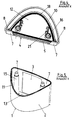
- Figur 3
- einen Schnitt nach der Linie B-B in Figur 1;
- Figur 4
- eine Ansicht aus Richtung X in das Innere des Abdeckteils;
- Figur 5
- eine Ansicht aus Richtung Y auf ein Gehäuseteil, auf welches das Abdeckteil aufgesetzt ist und
- Figur 6
- das Abdeckteil und das Gehäuseteil vor ihrem Zusammenbau.
- 1
- Gehäuseteil
- 2
- Seitenwand des Gehäuseteils
- 3
- Abschlußscheibe
- 4
- Abdeckteil
- 5
- Freimachung
- 6
- Seitenwand des Abdeckteils
- 7
- Randabschnitte der Freimachung
- 8
- Anlagefläche
- 9
- Aufsetzrichtung
- 10
- Auflaufschräge
- 11
- Rand
- 12
- Wand
- 13
- Halteplatte
- 14
- Ränder
- 15
- Befestigungsansatz
- 16
- Befestigungsöffnung
- 17
- Lampe
- 18
- Aufnahmebett
- 19
- Tülle
- 20
- Bereiche
- 21
- Halteelement
- 22
- Lampe
- 23
- Befestigungsschrauben
Claims (13)
- Leuchte für Fahrzeuge, insbesondere Kennzeichenleuchte für Fahrzeuge, mit einem außen am Fahrzeug befestigbaren Gehäuseteil (1), welches eine umlaufende Seitenwand (2) aufweist, die in einem Abschnitt von einer lichtdurchlässigen Abschlußscheibe (3) komplettiert ist und mit einem auf das Gehäuseteil (1) aufgesetzten Abdeckteil (4), welches mit seiner Innenseite an den freien Rand (11) der Seitenwand (2) des Gehäuseteils (1) angrenzend verläuft und eine Freimachung (5) für die lichtdurchlässige Abschlußscheibe (3) aufweist, dadurch gekennzeichnet, daßdas Gehäuseteil (1) mit seiner umlaufenden Seitenwand (2) und das Abdeckteil (4) mit einer die Freimachung (5) aufweisenden Seitenwand (6) ineinandergeschoben sind,seitliche Randabschnitte (7) der Freimachung (5) des Abdeckteils (4) mit ihren schmalen Seiten die Freimachung (5) begrenzen und mit ihrer Innenseite in einer gemeinsamen Fläche liegen und als Anlagefläche (8) für die Seitenwand (2) des Gehäuseteils (1) dienen.das Abdeckteil (4) zumindest mit einem der Anlagefläche (8) zugewandten Abschnitt seiner Seitenwand (4) sich entgegen seiner Aufsetzrichtung (9) verjüngt, wobei die Innenseite dieses Abschnitts als Auflaufschräge (10) für die Seitenwand (2) des Gehäuseteils (1) dient.
- Kennzeichenleuchte nach Anspruch 1, dadurch gekennzeichnet, daß das Abdeckteil (4) mit seiner Seitenwand (6) sich bis auf die Randabschnitte (7) der Freimachung (5) entgegen der Aufsetzrichtung (9) verjüngt und in diesem gesamten Bereich mit seiner Innenseite als Auflaufschräge (10) für das Gehäuseteil (1) dient.
- Kennzeichenleuchte nach Anspruch 1 oder 2, dadurch gekennzeichnet, daß die als Auflaufschräge (10) dienende Innenseite der Seitenwand (6) des Abdeckteils (4) und die der Auflaufschräge (10) zugewandte Außenseite der Seitenwand (2) des Gehäuseteils (1) einen nach außen geöffneten Spalt begrenzen, welcher sich zu seinem Grund hin verjüngt.
- Kennzeichenleuchte nach einem der Ansprüche 1 bis 3, dadurch gekennzeichnet, daß in Aufsetzrichtung (9) gesehen sowohl die Seitenwand (6) des Abdeckteils (4) als auch die Seitenwand (2) des Gehäuseteils (1) bis auf den Bereich der Abschlußscheibe (3) und ihrer Anlagefläche (8) in einem zur Abschlußscheibe (3) hin geöffneten Bogen verläuft.
- Kennzeichenleuchte nach einem der Ansprüche 1 bis 4, dadurch gekennzeichnet, daß die an den freien Rand (11) der Seitenwand (2) des Gehäuseteils (1) angrenzende Innenseite des Abdeckteils (4) von einer oberen Wand (12) des Abdeckteils (4) gebildet ist, welche mit ihrem äußeren Randbereich angrenzend zum freien Rand (11) der Seitenwand (2) des Gehäuseteils (1) verläuft.
- Kennzeichenleuchte nach einem der Ansprüche 1 bis 5, dadurch gekennzeichnet, daß die Auflaufschräge (10) des Abdeckteils (4) in einem spitzen Winkel (a) zu einer an das Fahrzeug anlegbaren Halteplatte (13) des Gehäuseteils (1) verläuft.
- Kennzeichenleuchte nach einem der Ansprüche 1 bis 6, dadurch gekennzeichnet, daß die der Auflaufschräge (10) zugewandte Außenseite der Seitenwand (2) des Gehäuseteils (1) zumindest abschnittsweise in einem stumpfen Winkel (b) zur Halteplatte (13) des Gehäuseteils (1) verläuft.
- Kennzeichenleuchte nach einem der Ansprüche 1 bis 7, dadurch gekennzeichnet, daß in den äußeren Randbereich der oberen Wand (12) des Abdeckteils (4) ein Aufnahmebett (18) eingebracht ist, in welche die umlaufende Seitenwand (2) des Gehäuseteils (1) dicht eingreift.
- Kennzeichenleuchte nach Anspruch 8, dadurch gekennzeichnet, daß das Aufnahmebett (18) in seinem Querschnitt u-förmig gestaltet ist, wobei die äußere Wand des Aufnahmebetts (18) von der Seitenwand (6) des Abdeckteils (4) gebildet ist und die innere Wand an die obere Wand (12) des Abdeckteils (4) angeformt ist.
- Kennzeichenleuchte nach einem der Ansprüche 1 bis 9, dadurch gekennzeichnet, daß die lichtdurchlässige Abschlußscheibe (3) und die sie aufnehmende Freimachung (5) mit ihren seitlichen Rändern (14) sich entgegen der Aufsetzrichtung (9) verjüngen, wobei die Freimachung (5) in Aufsetzrichtung (9) offen ausgeführt ist und die Außenseite der Abschlußscheibe (3) bündig zu dem angrenzenden Randabschnitt (7) der Freimachung (5) verläuft.
- Kennzeichenleuchte nach einem Ansprüche 1 bis 10, dadurch gekennzeichnet, daß an das Gehäuseteil (1) mindestens ein entgegen der Aufsetzrichtung (9) gerichteter Befestigungsansatz (15) angeformt ist, welcher sich zu einer Befestigungsöffnung (16) des Abdeckteils (4) hin erstreckt.
- Kennzeichenleuchte nach einem der Ansprüche 1 bis 11, dadurch gekennzeichnet, daß die obere Wand (12) des Abdeckteils (4) in einem spitzen Winkel (c) zur Abschlußscheibe (3) verläuft.
- Kennzeichenleuchte nach einem der Ansprüche 1 bis 12, dadurch gekennzeichnet, an der Innenseite der oberen Wand (12) des Abdeckteils (4) eine Lampe (17) gehaltert ist.
Applications Claiming Priority (2)
| Application Number | Priority Date | Filing Date | Title |
|---|---|---|---|
| DE19638063 | 1996-09-18 | ||
| DE19638063A DE19638063A1 (de) | 1996-09-18 | 1996-09-18 | Leuchte für Fahrzeuge, insbesondere Kennzeichenleuchte für Fahrzeuge |
Publications (3)
| Publication Number | Publication Date |
|---|---|
| EP0830983A2 true EP0830983A2 (de) | 1998-03-25 |
| EP0830983A3 EP0830983A3 (de) | 1999-03-03 |
| EP0830983B1 EP0830983B1 (de) | 2002-04-17 |
Family
ID=7806018
Family Applications (1)
| Application Number | Title | Priority Date | Filing Date |
|---|---|---|---|
| EP97115321A Expired - Lifetime EP0830983B1 (de) | 1996-09-18 | 1997-09-04 | Leuchte für Fahrzeuge |
Country Status (3)
| Country | Link |
|---|---|
| EP (1) | EP0830983B1 (de) |
| DE (2) | DE19638063A1 (de) |
| ES (1) | ES2175237T3 (de) |
Families Citing this family (1)
| Publication number | Priority date | Publication date | Assignee | Title |
|---|---|---|---|---|
| FI110079B (fi) * | 1997-10-17 | 2002-11-29 | Talmu Ab Oy | Lyhty |
Citations (1)
| Publication number | Priority date | Publication date | Assignee | Title |
|---|---|---|---|---|
| DE3836032A1 (de) | 1988-10-22 | 1990-04-26 | Hella Kg Hueck & Co | Leuchte fuer kraftfahrzeuge |
Family Cites Families (7)
| Publication number | Priority date | Publication date | Assignee | Title |
|---|---|---|---|---|
| BE423050A (de) * | ||||
| IT1128924B (it) * | 1980-07-10 | 1986-06-04 | Iao Industrie Riunite Spa | Gruppo ottico per autoveicoli |
| US4506314A (en) * | 1983-09-21 | 1985-03-19 | Moore Dennis G | Submersible signal lamp with interchangeable lens assembly |
| US5157377A (en) * | 1987-01-20 | 1992-10-20 | Mark Wayne | Hood scoop assembly |
| DE3723029C2 (de) * | 1987-07-11 | 1994-06-30 | Hella Kg Hueck & Co | Mehrkammerleuchte mit einem Kennzeichenschildhalter |
| DE4137612C1 (de) * | 1991-11-15 | 1993-05-06 | Hella Kg Hueck & Co, 4780 Lippstadt, De | |
| ES2088174T3 (es) * | 1992-03-03 | 1996-08-01 | Hella Kg Hueck & Co | Lampara para vehiculos. |
-
1996
- 1996-09-18 DE DE19638063A patent/DE19638063A1/de not_active Withdrawn
-
1997
- 1997-09-04 ES ES97115321T patent/ES2175237T3/es not_active Expired - Lifetime
- 1997-09-04 DE DE59707022T patent/DE59707022D1/de not_active Expired - Lifetime
- 1997-09-04 EP EP97115321A patent/EP0830983B1/de not_active Expired - Lifetime
Patent Citations (1)
| Publication number | Priority date | Publication date | Assignee | Title |
|---|---|---|---|---|
| DE3836032A1 (de) | 1988-10-22 | 1990-04-26 | Hella Kg Hueck & Co | Leuchte fuer kraftfahrzeuge |
Also Published As
| Publication number | Publication date |
|---|---|
| EP0830983B1 (de) | 2002-04-17 |
| DE19638063A1 (de) | 1998-03-19 |
| EP0830983A3 (de) | 1999-03-03 |
| DE59707022D1 (de) | 2002-05-23 |
| ES2175237T3 (es) | 2002-11-16 |
Similar Documents
| Publication | Publication Date | Title |
|---|---|---|
| EP2832497B1 (de) | Handgeführtes Arbeitsgerät | |
| DE69416568T2 (de) | Flugzeugsmarkierungsleuchter für Fahr- oder Rollbahnen | |
| EP0175121B1 (de) | Instrumententafel für Kraftfahrzeuge | |
| DE4323118C1 (de) | Vorrichtung zur lösbaren Anordnung einer Lampe an einem Reflektor eines Fahrzeugscheinwerfers | |
| DE3902229A1 (de) | Scheinwerfer | |
| DE9311132U1 (de) | Kniehebelspannvorrichtung für den Karosseriebau | |
| DE10010722A1 (de) | Dichtvorrichtung | |
| DE602004005628T2 (de) | Halterung mit mehreren Brücken | |
| EP0969985B1 (de) | Leuchte für fahrzeuge, insbesondere heckleuchte für fahrzeuge | |
| EP0830983B1 (de) | Leuchte für Fahrzeuge | |
| DE4024313A1 (de) | Versteifter aufbau des zylinderblocks eines verbrennungsmotors | |
| DE29504267U1 (de) | Kniehebelspannvorrichtung, insbesondere zur Verwendung im Karosseriebau der Kfz-Industrie | |
| EP0888954A1 (de) | Verschlussdeckel aus Kunststoff | |
| DE19716736C2 (de) | Einrichtung zur Sensorbefestigung | |
| DE3424205C2 (de) | Fahrzeugleuchte | |
| EP0299151A2 (de) | Mehrkammerleuchte mit einem Kennzeichenschildhalter | |
| DE3515527C2 (de) | ||
| DE4128534C1 (en) | Pivotable fixture for reflector of motor vehicle headlamp - provides pivotable point by pressed recess in outer housing edge serving as spring for groove in outer reflector edge | |
| DE3346383C1 (de) | Zweiteiliges Luftfiltergehäuse | |
| DE4126112C1 (de) | ||
| DE2826950C2 (de) | ||
| DE19522669C2 (de) | Gehäuse einer lichterzeugenden Einrichtung für Kraftfahrzeuge | |
| EP0937490A2 (de) | Filtereinrichtung in Modulbauweise | |
| DE2914959C2 (de) | Zusatzscheinwerfer für Kraftfahrzeuge | |
| DE19513369A1 (de) | Beleuchtungseinrichtung für Fahrzeuge |
Legal Events
| Date | Code | Title | Description |
|---|---|---|---|
| PUAI | Public reference made under article 153(3) epc to a published international application that has entered the european phase |
Free format text: ORIGINAL CODE: 0009012 |
|
| AK | Designated contracting states |
Kind code of ref document: A2 Designated state(s): DE ES FR GB IT |
|
| AX | Request for extension of the european patent |
Free format text: AL;LT;LV;RO;SI |
|
| PUAL | Search report despatched |
Free format text: ORIGINAL CODE: 0009013 |
|
| AK | Designated contracting states |
Kind code of ref document: A3 Designated state(s): AT BE CH DE DK ES FI FR GB GR IE IT LI LU MC NL PT SE |
|
| AX | Request for extension of the european patent |
Free format text: AL;LT;LV;RO;SI |
|
| 17P | Request for examination filed |
Effective date: 19990707 |
|
| AKX | Designation fees paid |
Free format text: DE ES FR GB IT |
|
| GRAG | Despatch of communication of intention to grant |
Free format text: ORIGINAL CODE: EPIDOS AGRA |
|
| 17Q | First examination report despatched |
Effective date: 20010530 |
|
| GRAG | Despatch of communication of intention to grant |
Free format text: ORIGINAL CODE: EPIDOS AGRA |
|
| GRAH | Despatch of communication of intention to grant a patent |
Free format text: ORIGINAL CODE: EPIDOS IGRA |
|
| REG | Reference to a national code |
Ref country code: GB Ref legal event code: IF02 |
|
| GRAH | Despatch of communication of intention to grant a patent |
Free format text: ORIGINAL CODE: EPIDOS IGRA |
|
| GRAA | (expected) grant |
Free format text: ORIGINAL CODE: 0009210 |
|
| AK | Designated contracting states |
Kind code of ref document: B1 Designated state(s): DE ES FR GB IT |
|
| PG25 | Lapsed in a contracting state [announced via postgrant information from national office to epo] |
Ref country code: GB Free format text: LAPSE BECAUSE OF FAILURE TO SUBMIT A TRANSLATION OF THE DESCRIPTION OR TO PAY THE FEE WITHIN THE PRESCRIBED TIME-LIMIT Effective date: 20020417 |
|
| REF | Corresponds to: |
Ref document number: 59707022 Country of ref document: DE Date of ref document: 20020523 |
|
| ET | Fr: translation filed | ||
| GBV | Gb: ep patent (uk) treated as always having been void in accordance with gb section 77(7)/1977 [no translation filed] |
Effective date: 20020417 |
|
| REG | Reference to a national code |
Ref country code: ES Ref legal event code: FG2A Ref document number: 2175237 Country of ref document: ES Kind code of ref document: T3 |
|
| PLBE | No opposition filed within time limit |
Free format text: ORIGINAL CODE: 0009261 |
|
| STAA | Information on the status of an ep patent application or granted ep patent |
Free format text: STATUS: NO OPPOSITION FILED WITHIN TIME LIMIT |
|
| 26N | No opposition filed |
Effective date: 20030120 |
|
| PGFP | Annual fee paid to national office [announced via postgrant information from national office to epo] |
Ref country code: IT Payment date: 20060930 Year of fee payment: 10 |
|
| PG25 | Lapsed in a contracting state [announced via postgrant information from national office to epo] |
Ref country code: IT Free format text: LAPSE BECAUSE OF NON-PAYMENT OF DUE FEES Effective date: 20070904 |
|
| PGFP | Annual fee paid to national office [announced via postgrant information from national office to epo] |
Ref country code: FR Payment date: 20120926 Year of fee payment: 16 |
|
| PGFP | Annual fee paid to national office [announced via postgrant information from national office to epo] |
Ref country code: ES Payment date: 20121004 Year of fee payment: 16 |
|
| REG | Reference to a national code |
Ref country code: DE Ref legal event code: R084 Ref document number: 59707022 Country of ref document: DE Effective date: 20130606 |
|
| REG | Reference to a national code |
Ref country code: FR Ref legal event code: ST Effective date: 20140530 |
|
| PG25 | Lapsed in a contracting state [announced via postgrant information from national office to epo] |
Ref country code: FR Free format text: LAPSE BECAUSE OF NON-PAYMENT OF DUE FEES Effective date: 20130930 |
|
| REG | Reference to a national code |
Ref country code: ES Ref legal event code: FD2A Effective date: 20141007 |
|
| PG25 | Lapsed in a contracting state [announced via postgrant information from national office to epo] |
Ref country code: ES Free format text: LAPSE BECAUSE OF NON-PAYMENT OF DUE FEES Effective date: 20130905 |
|
| PGFP | Annual fee paid to national office [announced via postgrant information from national office to epo] |
Ref country code: DE Payment date: 20160831 Year of fee payment: 20 |
|
| REG | Reference to a national code |
Ref country code: DE Ref legal event code: R071 Ref document number: 59707022 Country of ref document: DE |