EP0831041A1 - Dispositif de transfert d'objets - Google Patents
Dispositif de transfert d'objets Download PDFInfo
- Publication number
- EP0831041A1 EP0831041A1 EP97402147A EP97402147A EP0831041A1 EP 0831041 A1 EP0831041 A1 EP 0831041A1 EP 97402147 A EP97402147 A EP 97402147A EP 97402147 A EP97402147 A EP 97402147A EP 0831041 A1 EP0831041 A1 EP 0831041A1
- Authority
- EP
- European Patent Office
- Prior art keywords
- swing
- main
- transfer line
- coupling system
- unloading
- Prior art date
- Legal status (The legal status is an assumption and is not a legal conclusion. Google has not performed a legal analysis and makes no representation as to the accuracy of the status listed.)
- Granted
Links
- 239000000725 suspension Substances 0.000 claims abstract description 17
- 230000008878 coupling Effects 0.000 claims abstract description 16
- 238000010168 coupling process Methods 0.000 claims abstract description 16
- 238000005859 coupling reaction Methods 0.000 claims abstract description 16
- 238000000926 separation method Methods 0.000 claims abstract description 6
- 238000006073 displacement reaction Methods 0.000 claims description 11
- 238000004519 manufacturing process Methods 0.000 description 4
- 230000005540 biological transmission Effects 0.000 description 2
- 238000010276 construction Methods 0.000 description 2
- 230000000694 effects Effects 0.000 description 1
- 230000007774 longterm Effects 0.000 description 1
- 230000002441 reversible effect Effects 0.000 description 1
- 238000005096 rolling process Methods 0.000 description 1
Images



Classifications
-
- B—PERFORMING OPERATIONS; TRANSPORTING
- B62—LAND VEHICLES FOR TRAVELLING OTHERWISE THAN ON RAILS
- B62D—MOTOR VEHICLES; TRAILERS
- B62D65/00—Designing, manufacturing, e.g. assembling, facilitating disassembly, or structurally modifying motor vehicles or trailers, not otherwise provided for
- B62D65/02—Joining sub-units or components to, or positioning sub-units or components with respect to, body shell or other sub-units or components
- B62D65/18—Transportation, conveyor or haulage systems specially adapted for motor vehicle or trailer assembly lines
-
- B—PERFORMING OPERATIONS; TRANSPORTING
- B65—CONVEYING; PACKING; STORING; HANDLING THIN OR FILAMENTARY MATERIAL
- B65G—TRANSPORT OR STORAGE DEVICES, e.g. CONVEYORS FOR LOADING OR TIPPING, SHOP CONVEYOR SYSTEMS OR PNEUMATIC TUBE CONVEYORS
- B65G17/00—Conveyors having an endless traction element, e.g. a chain, transmitting movement to a continuous or substantially-continuous load-carrying surface or to a series of individual load-carriers; Endless-chain conveyors in which the chains form the load-carrying surface
- B65G17/20—Conveyors having an endless traction element, e.g. a chain, transmitting movement to a continuous or substantially-continuous load-carrying surface or to a series of individual load-carriers; Endless-chain conveyors in which the chains form the load-carrying surface comprising load-carriers suspended from overhead traction chains
-
- B—PERFORMING OPERATIONS; TRANSPORTING
- B65—CONVEYING; PACKING; STORING; HANDLING THIN OR FILAMENTARY MATERIAL
- B65G—TRANSPORT OR STORAGE DEVICES, e.g. CONVEYORS FOR LOADING OR TIPPING, SHOP CONVEYOR SYSTEMS OR PNEUMATIC TUBE CONVEYORS
- B65G47/00—Article or material-handling devices associated with conveyors; Methods employing such devices
- B65G47/52—Devices for transferring articles or materials between conveyors i.e. discharging or feeding devices
- B65G47/60—Devices for transferring articles or materials between conveyors i.e. discharging or feeding devices to or from conveyors of the suspended, e.g. trolley, type
- B65G47/61—Devices for transferring articles or materials between conveyors i.e. discharging or feeding devices to or from conveyors of the suspended, e.g. trolley, type for articles
-
- B—PERFORMING OPERATIONS; TRANSPORTING
- B65—CONVEYING; PACKING; STORING; HANDLING THIN OR FILAMENTARY MATERIAL
- B65G—TRANSPORT OR STORAGE DEVICES, e.g. CONVEYORS FOR LOADING OR TIPPING, SHOP CONVEYOR SYSTEMS OR PNEUMATIC TUBE CONVEYORS
- B65G2201/00—Indexing codes relating to handling devices, e.g. conveyors, characterised by the type of product or load being conveyed or handled
- B65G2201/02—Articles
Definitions
- the invention relates to an object transfer device where each object is supported by a swing, which includes means for swing suspension and main drive means allowing the swing of the swing on a transfer line main.
- each workstation requires a different passage time of the object treated according to the type of operation carried out.
- some transfer devices have individual management of the movement speed of each swing. This solution is economically very heavy to support.
- the invention intends to remedy these drawbacks by proposing a transfer device, most of which is little expensive, by a simplified construction, which however allows some places, a different speed of movement of the swings compared to the rest of the transfer device.
- the invention aims to provide a main transfer device for simple construction (monorail chain, constant transfer speed for all swings) on which it is possible, in places wanted, to carry out a treatment of longer duration on the object carried by the swing.
- the means for suspending the swing have a first coupling system element and a surface support
- the main drive means include a second coupling system element capable of cooperating in a manner reversible with the first coupling system element so to form a removable connection between the suspension means and the main drive means
- the object transfer device further comprising unloading means allowing the separation and distance of the swing from the line of main transfer and comprising support means capable of cooperate with said bearing surface, separation means between the first and second coupling system elements, and means of lateral movement of the swing connected to the means of support.
- the first coupling system element includes a lug
- the second element of the coupling system is a hook open upwards
- the transfer device having means for vertical lifting of the support means allowing the uncoupling between the lug and the hook and that the means of lateral displacement allow displacement of the support means in the raised position in a direction orthogonal to the line of main transfer.
- the means of support include a track of rollers and in that the means of suspension of the swing also have two connected uprights between them by a horizontal unloading bar whose surface lower constitutes said bearing surface, each upright having a lug.
- the main drive means further include a chain of monorail transfer on which regularly spaced hooks move at constant speed.
- the main advantage of the invention lies in the possibility of unhook the swings at a place on the main transfer line where the processing operation to be performed on the object takes a long time before hanging the swings in the main transfer line which constitutes an endless circuit of very economical design since it consists of a single speed monorail chain.
- the swing is unhooked, we can design several circuits possible before the return of this swing on the main transfer line.
- the swing is unhooked, it is moved away from the main transfer line, this place the planned treatment and we put back, by hanging, the swing in the main transfer line, in the same place as when dropout.
- the swing, once unhooked is placed on another transfer chain which has a beginning and end, the swing then moving at a different speed of the speed of the main transfer line and this swing is at new hung up on the main transfer line at the final end of this secondary transfer line.
- the transfer device according to the invention can serve as a switch between two transfer chains in closed loop with different movement speeds, the invention then to pass the swings of a chain transfer to another.
- This referral can be made between chains of parallel transfers between them, possibly placed on several levels, or radial transfer chains converging on a station rotary unloading.
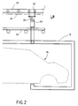
- the transfer device 10 allows the movement of a number of swings 12 supporting motor vehicles 14 during manufacture.
- Means of suspension 16 of the swing 12 are fixed to the top of the swing and connect it to the main transfer line 18 along which are conveyed the swings 12 from one work station to another.
- the main transfer line is a chain closed circuit along which workstations are placed successive for the assembly and production of a motor vehicle.
- the line of main transfer 18 a monorail chain.
- the main transfer line 18 is a conveyor monorail which includes a single rail 20 on which rollers roll 22 swivels which are in constant rotation at uniform speed, these rollers 22 are towed by a transmission chain (not shown) of axis 24.
- the rail 20 has, in cross section, a shaped section 20 of I on which, thanks to the rotation of the rollers 22, will slide a trolley 26 connected to the swing 12.
- the trolley 26 preferably has, in front view ( Figure 3), a ring shape open or ⁇ upside down with its two free ends 28 placed on either side of the vertical central wing of the transport rail 20.
- the transmission chain is fixed on the trolley 26 so as to train it in its movement of movement along the line of main transfer 18.
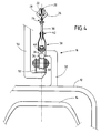
- a hook 30 with an opening upwards is connected in the vertical extension, downwards, of two trolleys 26 consecutive and serves to support the suspension means 16 which is fixed the swing 12.
- the trolley 26 has ( Figure 4) two free ends 28 on which are symmetrically mounted two rollers 22.
- the surface bearing 29 or periphery of each roller 22 rests on this rail 20, at the level of the upper surface of the lower horizontal wing of the I.
- FIG. 5 illustrating the swing on the line of main transfer, with no possibility of unloading this swing since this swing 12 is not opposite the means of unloading.
- the swinging suspension means 16 comprise two vertical uprights 32 fixed at the front and at the rear of the swing 12, these two uprights being connected together by an unloading bar horizontal 34, preferably of circular section.
- the surface lower 36 of the unloading bar 34 is bare and free to access because it constitutes a bearing surface for unloading the swing.
- the amount 32 is shaped from L overturned, the unloading bar 34 is placed under the branch horizontal of this L and a U-shaped stirrup 38, the base 40 of which is placed above the horizontal branch of the L, extends vertically the amount 32, upwards.
- a lug 42 forming a horizontal axis perpendicular to the bar unloading 34 closes the opening of the stirrup 38 and will constitute the point of attachment of the suspension means 16 on the line of main transfer 18.
- the lug 42 is placed in the hollow of the hook 30 so that two consecutive hooks 30 placed on the line main transfer 18 support a swing 12.
- the system coupling consists of a hook 30 cooperating with a lug 42 but other coupling systems can be envisaged for non-permanently connect the suspension means of swing 16 to the main drive means constituting the main transfer line 18 - for example we can consider other mechanical connections or a magnetic connection between magnets-.
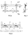
- rollers 50 are pivotally mounted on a section beam U-shaped cross section which thus constitutes a bearing for unloading bar 34.
- This U-shaped beam 52 is fixed on at least one rack 54 consisting of an L-shaped bar whose face upper part of the horizontal part is rigidly fixed under the bottom of the U-shaped beam 52.
- the two racks 54 are placed at a certain distance from each other and their lower part supports the two end portions of the U-shaped beam 52 inside which are distributed at equal distance from the rollers 50 connected together by a drive element such as a chain which generates a line of secondary transfer.
- the upper part of the racks 54 carries teeth 56 allowing it to rest on at least two pinions 58 of axis horizontal placed on either side of the rack and pivoted on an upper horizontal beam 60, parallel to the shaped beam from U 52, and parallel to the main transfer line 18, i.e. at rail 20.
- the upper horizontal beam 60 carries each from its ends a slide 62 perpendicular to the direction main beam 60 and able to move by rolling or by sliding on a horizontal rail 64 which is orthogonal to the line of main transfer 18 and which constitutes the raceway for the lateral displacement.
- rollers 50 preferably constitute a track of rollers allowing the displacement of a swing according to a very slow speed for carrying out a long-term operation on the object transported by the swing, the swing arriving on one of the ends of this pebble path.
- the rollers 50 can have their own rotation system thanks to looped chains connecting two consecutive rollers and a drive motor which rotates at least one roller 50 of the roller track.
- This track of pebbles 50 is of limited length since it undergoes the lateral displacement of the unloading assembly but it is possible provide that when the unloading means are in the position set aside from the main transfer line, the path of rollers 50 extends on a fixed secondary transfer line, with a another pebble path at the end of which is a second set unloading which will be used to put the swing back on the main transfer.
Landscapes
- Engineering & Computer Science (AREA)
- Mechanical Engineering (AREA)
- Manufacturing & Machinery (AREA)
- Chemical & Material Sciences (AREA)
- Combustion & Propulsion (AREA)
- Transportation (AREA)
- Chain Conveyers (AREA)
- Specific Conveyance Elements (AREA)
- Intermediate Stations On Conveyors (AREA)
- Control And Other Processes For Unpacking Of Materials (AREA)
Abstract
Description
- la figure 1 est une vue longitudinale de face d'une portion du dispositif de transfert selon l'invention dans le cas où une balancelle est au niveau des moyens de déchargement ;
- la figure 2 est une vue agrandie de la figure 1 représentant la partie avant de la balancelle avec un montant des moyens de support ;
- la figure 3 est une vue latérale selon la direction III de la figure 2 représentant le montant de l'avant de la balancelle et la coopération entre les moyens de suspension de la balancelle et une partie des moyens de déchargement ;
- la figure 4 est une vue agrandie de la figure 3 dans la zone de liaison entre les moyens de suspension et les moyens de déchargement ;
- la figure 5 est une vue identique à celle de la figure 4 dans le cas où la balancelle n'est pas en regard des moyens de déchargement ;
- la figure 6 est une vue longitudinale schématique des moyens de déchargement de la balancelle ;
- la figure 7 est une vue latérale de la figure 6 selon la direction VII -VII de la figure 6 ; et,
- la figure 8 est une vue du dessus des moyens de déchargement placés à côté et parallèlement à la ligne de transfert principale.
Claims (5)
- Dispositif de transfert (10) d'objets, chaque objet étant supporté par une balancelle (12), qui comprend des moyens de suspension (16) de balancelle possédant un premier élément de système d'accouplement (42) et une surface d'appui (36), des moyens d'entraínement principaux (20, 22, 24) permettant le déplacement de la balancelle sur une ligne de transfert principale (18) et comportant un deuxième élément de système d'accouplement (30) pouvant coopérer de manière réversible avec ledit premier élément de système d'accouplement (42) de façon à former une liaison amovible entre les moyens de suspension (16) et les moyens d'entraínement principaux (20, 22, 24), et des moyens de déchargement permettant la séparation et l'éloignement de la balancelle (12) par rapport à la ligne de transfert principale (18) et comportant:caractérisé en ce que ledit premier élément de système d'accouplement comprend un ergot (42), en ce que ledit deuxième élément de système d'accouplement est un crochet (30) ouvert vers le haut, en ce que les moyens de support comportent un chemin de galets et en ce que les moyens de suspension (16) de la balancelle possèdent en outre deux montants (32) reliés entre eux par une barre de déchargement horizontale (34) dont la surface inférieure constitue ladite surface d'appui (36), chaque montant ayant un ergot (42).des moyens de support (50, 52) pouvant coopérer avec ladite surface d'appui,des moyens de séparation possédant des moyens de soulèvement vertical (54, 56) des moyens de support permettant le désaccouplement entre le premier et le deuxième éléments de système d'accouplement, etdes moyens de déplacement latéral de la balancelle reliés aux moyens de support et permettant un déplacement des moyens de support en position soulevée selon une direction orthogonale à la ligne de transfert principale (18),
- Dispositif de transfert (10) selon la revendication 1, caractérisé en ce que les moyens d'entraínement principaux comportent en outre une chaíne de transfert monorail sur laquelle des crochets (30) régulièrement espacés se déplacent à vitesse constante.
- Dispositif de transfert (10) selon la revendication 1, caractérisé en ce que ledit chemin de galets comprend des galets (50) montés pivotants dans une poutre en horizontale (52) de section en forme de U et reliés entre eux par un élément d'entraínement, et constitue une ligne de transfert secondaire.
- Dispositif de transfert selon la revendication 3, caractérisé en ce que les moyens de soulèvement vertical comprennent au moins une crémaillère (54) verticale fixée à ladite poutre en U, le mouvement de translation verticale de chaque crémaillère étant permis par engrènement entre les dents (56) de la crémaillère avec au moins deux pignons (58) d'axe horizontal placés de part et d'autre de la crémaillère (54) et montés sur une poutre horizontale supérieure (60) et parallèle à la ligne de transfert principale (18).
- Dispositif de transfert selon la revendication 4, caractérisé en ce que les moyens de déplacement latéral comprennent au moins un rail horizontal orthogonal (64) à la ligne de transfert principale (18) et constituant le chemin de roulement de ladite poutre horizontale (60).
Applications Claiming Priority (2)
| Application Number | Priority Date | Filing Date | Title |
|---|---|---|---|
| FR9611421A FR2753441B1 (fr) | 1996-09-19 | 1996-09-19 | Dispositif de transfert d'objets |
| FR9611421 | 1996-09-19 |
Publications (2)
| Publication Number | Publication Date |
|---|---|
| EP0831041A1 true EP0831041A1 (fr) | 1998-03-25 |
| EP0831041B1 EP0831041B1 (fr) | 2000-12-27 |
Family
ID=9495883
Family Applications (1)
| Application Number | Title | Priority Date | Filing Date |
|---|---|---|---|
| EP97402147A Expired - Lifetime EP0831041B1 (fr) | 1996-09-19 | 1997-09-17 | Dispositif de transfert d'objets |
Country Status (4)
| Country | Link |
|---|---|
| EP (1) | EP0831041B1 (fr) |
| AT (1) | ATE198309T1 (fr) |
| DE (1) | DE69703775D1 (fr) |
| FR (1) | FR2753441B1 (fr) |
Cited By (1)
| Publication number | Priority date | Publication date | Assignee | Title |
|---|---|---|---|---|
| EP1104737A1 (fr) * | 1999-12-01 | 2001-06-06 | Dürr Automotion | Dispositif de transfert d'objets |
Citations (2)
| Publication number | Priority date | Publication date | Assignee | Title |
|---|---|---|---|---|
| LU65944A1 (fr) * | 1971-08-24 | 1973-01-15 | ||
| DE2910780A1 (de) * | 1979-03-19 | 1980-09-25 | Hajtomuevek Es Festoberendeze | Gehaengeuebergabevorrichtung fuer haengekettenfoerderer |
-
1996
- 1996-09-19 FR FR9611421A patent/FR2753441B1/fr not_active Expired - Fee Related
-
1997
- 1997-09-17 DE DE69703775T patent/DE69703775D1/de not_active Expired - Lifetime
- 1997-09-17 EP EP97402147A patent/EP0831041B1/fr not_active Expired - Lifetime
- 1997-09-17 AT AT97402147T patent/ATE198309T1/de not_active IP Right Cessation
Patent Citations (2)
| Publication number | Priority date | Publication date | Assignee | Title |
|---|---|---|---|---|
| LU65944A1 (fr) * | 1971-08-24 | 1973-01-15 | ||
| DE2910780A1 (de) * | 1979-03-19 | 1980-09-25 | Hajtomuevek Es Festoberendeze | Gehaengeuebergabevorrichtung fuer haengekettenfoerderer |
Cited By (1)
| Publication number | Priority date | Publication date | Assignee | Title |
|---|---|---|---|---|
| EP1104737A1 (fr) * | 1999-12-01 | 2001-06-06 | Dürr Automotion | Dispositif de transfert d'objets |
Also Published As
| Publication number | Publication date |
|---|---|
| EP0831041B1 (fr) | 2000-12-27 |
| FR2753441B1 (fr) | 1998-12-04 |
| ATE198309T1 (de) | 2001-01-15 |
| DE69703775D1 (de) | 2001-02-01 |
| FR2753441A1 (fr) | 1998-03-20 |
Similar Documents
| Publication | Publication Date | Title |
|---|---|---|
| EP0050245B1 (fr) | Installation pour l'enlèvement et la réception automatiques de charges par l'intermédiaire de véhicules de transport | |
| FR2480631A1 (fr) | Procede de tri ou de transport et installation et chariot pour sa mise en oeuvre | |
| FR2752554A1 (fr) | Rancher porteur a moyen de levage integre et ensemble porteur constitue d'au moins un couple de deux ranchers lies fonctionnellement entre eux | |
| FR2646136A1 (fr) | Appareil autonome d'embarquement et de debarquement de charges, integre a un aeronef | |
| EP1560744A1 (fr) | Convoyeur aerien a bras pendulaires entraines suivant un circuit en boucle fermee | |
| CA1284123C (fr) | Installation de transport a cables aeriens | |
| FR2806937A1 (fr) | Dispositif de tri selectif automatique | |
| EP1104737A1 (fr) | Dispositif de transfert d'objets | |
| EP0831041B1 (fr) | Dispositif de transfert d'objets | |
| EP0993877A1 (fr) | Station d'examen visuel de fruits | |
| WO1993015000A1 (fr) | Dispositif pour faciliter le transport des regimes de bananes lors de leur recolte | |
| FR2591174A1 (fr) | Installation de transport a cables aeriens dont les vehicules sont associes aux cables par au moins deux suspentes | |
| FR2582188A1 (fr) | Installation de manutention de tablettes sous serres | |
| FR2499953A1 (fr) | Dispositif convoyeur entre des postes a des niveaux differents | |
| FR2505797A1 (fr) | Appareillage automatique de transport a elements pendulaires destine a deplacer des barres et des listeaux, tels que des baguettes d'encadrements en bois | |
| US1132713A (en) | Conveyer. | |
| FR2640944A1 (fr) | ||
| BE1003872A5 (fr) | Systeme de support sur voie. | |
| CH619656A5 (en) | Handling device comprising an overhead track | |
| EP1057775B1 (fr) | Dispositif d'accrochage d'un élément d'un véhicule automobile à un moyen de manutention sur une chaíne de montage | |
| BE835127R (fr) | Appareil pour la distribution et/ou la reception automatiques d'articles | |
| FR2601663A1 (fr) | Perfectionnements aux elevateurs | |
| FR2634471A1 (fr) | Dispositif pour le positionnement et l'arret d'objets deplaces sur un transporteur | |
| FR2546462A1 (fr) | Appareil pour le convoyage automatique d'objets sur un reseau de convoyeurs | |
| EP0034550A2 (fr) | Dispositif de transfert de barres |
Legal Events
| Date | Code | Title | Description |
|---|---|---|---|
| PUAI | Public reference made under article 153(3) epc to a published international application that has entered the european phase |
Free format text: ORIGINAL CODE: 0009012 |
|
| AK | Designated contracting states |
Kind code of ref document: A1 Designated state(s): AT BE CH DE ES FR GB IE IT LI NL PT SE |
|
| AX | Request for extension of the european patent |
Free format text: AL;LT;LV;RO;SI |
|
| 17P | Request for examination filed |
Effective date: 19980922 |
|
| AKX | Designation fees paid |
Free format text: AT BE CH DE ES FR GB IE IT LI NL PT SE |
|
| AXX | Extension fees paid |
Free format text: RO PAYMENT 980922;SI PAYMENT 980922 |
|
| RBV | Designated contracting states (corrected) |
Designated state(s): AT BE CH DE ES FR GB IE IT LI NL PT SE |
|
| 17Q | First examination report despatched |
Effective date: 19990917 |
|
| RAP1 | Party data changed (applicant data changed or rights of an application transferred) |
Owner name: DUERR SYSTEMS FRANCE SA |
|
| GRAG | Despatch of communication of intention to grant |
Free format text: ORIGINAL CODE: EPIDOS AGRA |
|
| GRAG | Despatch of communication of intention to grant |
Free format text: ORIGINAL CODE: EPIDOS AGRA |
|
| GRAH | Despatch of communication of intention to grant a patent |
Free format text: ORIGINAL CODE: EPIDOS IGRA |
|
| GRAH | Despatch of communication of intention to grant a patent |
Free format text: ORIGINAL CODE: EPIDOS IGRA |
|
| GRAA | (expected) grant |
Free format text: ORIGINAL CODE: 0009210 |
|
| AK | Designated contracting states |
Kind code of ref document: B1 Designated state(s): AT BE CH DE ES FR GB IE IT LI NL PT SE |
|
| AX | Request for extension of the european patent |
Free format text: RO PAYMENT 19980922;SI PAYMENT 19980922 |
|
| PG25 | Lapsed in a contracting state [announced via postgrant information from national office to epo] |
Ref country code: SE Free format text: THE PATENT HAS BEEN ANNULLED BY A DECISION OF A NATIONAL AUTHORITY Effective date: 20001227 Ref country code: NL Free format text: LAPSE BECAUSE OF FAILURE TO SUBMIT A TRANSLATION OF THE DESCRIPTION OR TO PAY THE FEE WITHIN THE PRESCRIBED TIME-LIMIT Effective date: 20001227 Ref country code: IT Free format text: LAPSE BECAUSE OF FAILURE TO SUBMIT A TRANSLATION OF THE DESCRIPTION OR TO PAY THE FEE WITHIN THE PRESCRIBED TIME-LIMIT;WARNING: LAPSES OF ITALIAN PATENTS WITH EFFECTIVE DATE BEFORE 2007 MAY HAVE OCCURRED AT ANY TIME BEFORE 2007. THE CORRECT EFFECTIVE DATE MAY BE DIFFERENT FROM THE ONE RECORDED. Effective date: 20001227 Ref country code: IE Free format text: LAPSE BECAUSE OF FAILURE TO SUBMIT A TRANSLATION OF THE DESCRIPTION OR TO PAY THE FEE WITHIN THE PRESCRIBED TIME-LIMIT Effective date: 20001227 Ref country code: GB Free format text: LAPSE BECAUSE OF FAILURE TO SUBMIT A TRANSLATION OF THE DESCRIPTION OR TO PAY THE FEE WITHIN THE PRESCRIBED TIME-LIMIT Effective date: 20001227 Ref country code: ES Free format text: THE PATENT HAS BEEN ANNULLED BY A DECISION OF A NATIONAL AUTHORITY Effective date: 20001227 Ref country code: AT Free format text: LAPSE BECAUSE OF FAILURE TO SUBMIT A TRANSLATION OF THE DESCRIPTION OR TO PAY THE FEE WITHIN THE PRESCRIBED TIME-LIMIT Effective date: 20001227 |
|
| REF | Corresponds to: |
Ref document number: 198309 Country of ref document: AT Date of ref document: 20010115 Kind code of ref document: T |
|
| REG | Reference to a national code |
Ref country code: CH Ref legal event code: EP |
|
| REF | Corresponds to: |
Ref document number: 69703775 Country of ref document: DE Date of ref document: 20010201 |
|
| REG | Reference to a national code |
Ref country code: IE Ref legal event code: FG4D Free format text: FRENCH |
|
| PG25 | Lapsed in a contracting state [announced via postgrant information from national office to epo] |
Ref country code: PT Free format text: LAPSE BECAUSE OF FAILURE TO SUBMIT A TRANSLATION OF THE DESCRIPTION OR TO PAY THE FEE WITHIN THE PRESCRIBED TIME-LIMIT Effective date: 20010327 |
|
| PG25 | Lapsed in a contracting state [announced via postgrant information from national office to epo] |
Ref country code: DE Free format text: LAPSE BECAUSE OF FAILURE TO SUBMIT A TRANSLATION OF THE DESCRIPTION OR TO PAY THE FEE WITHIN THE PRESCRIBED TIME-LIMIT Effective date: 20010328 |
|
| NLV1 | Nl: lapsed or annulled due to failure to fulfill the requirements of art. 29p and 29m of the patents act | ||
| GBV | Gb: ep patent (uk) treated as always having been void in accordance with gb section 77(7)/1977 [no translation filed] |
Effective date: 20001227 |
|
| PG25 | Lapsed in a contracting state [announced via postgrant information from national office to epo] |
Ref country code: LI Free format text: LAPSE BECAUSE OF NON-PAYMENT OF DUE FEES Effective date: 20010930 Ref country code: CH Free format text: LAPSE BECAUSE OF NON-PAYMENT OF DUE FEES Effective date: 20010930 Ref country code: BE Free format text: LAPSE BECAUSE OF NON-PAYMENT OF DUE FEES Effective date: 20010930 |
|
| PLBE | No opposition filed within time limit |
Free format text: ORIGINAL CODE: 0009261 |
|
| STAA | Information on the status of an ep patent application or granted ep patent |
Free format text: STATUS: NO OPPOSITION FILED WITHIN TIME LIMIT |
|
| REG | Reference to a national code |
Ref country code: IE Ref legal event code: FD4D |
|
| 26N | No opposition filed | ||
| BERE | Be: lapsed |
Owner name: S.A. DURR SYSTEMS FRANCE Effective date: 20010930 |
|
| REG | Reference to a national code |
Ref country code: CH Ref legal event code: PL |
|
| PGFP | Annual fee paid to national office [announced via postgrant information from national office to epo] |
Ref country code: FR Payment date: 20020905 Year of fee payment: 6 |
|
| PG25 | Lapsed in a contracting state [announced via postgrant information from national office to epo] |
Ref country code: FR Free format text: LAPSE BECAUSE OF NON-PAYMENT OF DUE FEES Effective date: 20040528 |
|
| REG | Reference to a national code |
Ref country code: FR Ref legal event code: ST |