EP0831198A1 - Bügelschloss - Google Patents
Bügelschloss Download PDFInfo
- Publication number
- EP0831198A1 EP0831198A1 EP97115634A EP97115634A EP0831198A1 EP 0831198 A1 EP0831198 A1 EP 0831198A1 EP 97115634 A EP97115634 A EP 97115634A EP 97115634 A EP97115634 A EP 97115634A EP 0831198 A1 EP0831198 A1 EP 0831198A1
- Authority
- EP
- European Patent Office
- Prior art keywords
- bracket
- driver
- lock according
- shackle
- lock
- Prior art date
- Legal status (The legal status is an assumption and is not a legal conclusion. Google has not performed a legal analysis and makes no representation as to the accuracy of the status listed.)
- Granted
Links
- 238000006073 displacement reaction Methods 0.000 claims abstract description 15
- 230000000903 blocking effect Effects 0.000 claims description 20
- 230000006835 compression Effects 0.000 claims description 10
- 238000007906 compression Methods 0.000 claims description 10
- 238000003780 insertion Methods 0.000 claims description 6
- 230000037431 insertion Effects 0.000 claims description 6
- 238000000034 method Methods 0.000 claims description 5
- 239000000463 material Substances 0.000 claims description 2
- 230000001960 triggered effect Effects 0.000 claims description 2
- 239000003795 chemical substances by application Substances 0.000 description 2
- 230000036316 preload Effects 0.000 description 2
- 230000001133 acceleration Effects 0.000 description 1
- 238000005452 bending Methods 0.000 description 1
- 230000015572 biosynthetic process Effects 0.000 description 1
- 239000011248 coating agent Substances 0.000 description 1
- 238000000576 coating method Methods 0.000 description 1
- 230000000295 complement effect Effects 0.000 description 1
- 230000000694 effects Effects 0.000 description 1
- 238000010409 ironing Methods 0.000 description 1
- 230000008092 positive effect Effects 0.000 description 1
Images


Classifications
-
- E—FIXED CONSTRUCTIONS
- E05—LOCKS; KEYS; WINDOW OR DOOR FITTINGS; SAFES
- E05B—LOCKS; ACCESSORIES THEREFOR; HANDCUFFS
- E05B67/00—Padlocks; Details thereof
- E05B67/06—Shackles; Arrangement of the shackle
- E05B67/063—Padlocks with removable shackles
-
- E—FIXED CONSTRUCTIONS
- E05—LOCKS; KEYS; WINDOW OR DOOR FITTINGS; SAFES
- E05B—LOCKS; ACCESSORIES THEREFOR; HANDCUFFS
- E05B67/00—Padlocks; Details thereof
- E05B67/06—Shackles; Arrangement of the shackle
- E05B67/22—Padlocks with sliding shackles, with or without rotary or pivotal movement
- E05B67/24—Padlocks with sliding shackles, with or without rotary or pivotal movement with built- in cylinder locks
-
- E—FIXED CONSTRUCTIONS
- E05—LOCKS; KEYS; WINDOW OR DOOR FITTINGS; SAFES
- E05C—BOLTS OR FASTENING DEVICES FOR WINGS, SPECIALLY FOR DOORS OR WINDOWS
- E05C9/00—Arrangements of simultaneously actuated bolts or other securing devices at well-separated positions on the same wing
- E05C9/04—Arrangements of simultaneously actuated bolts or other securing devices at well-separated positions on the same wing with two sliding bars moved in opposite directions when fastening or unfastening
Definitions
- the invention relates to a padlock, in particular a two-wheel lock, with a lock body and one in this when the Key lockable bracket, the two Temple ends in the locking position in one bracket receptacle are held and by means of at least one temple end one in a recess provided in the end region of the bracket engaging bolt is lockable.
- An object of the invention is a padlock of the type mentioned in such a way that the Risk of breaking open is reduced.
- this object is achieved in that the Latch in its locked position by a blocking element are blocked.
- the bolt is in the lock body locked bracket not only by means of a spring held in the recess of the bracket, but additionally by means of a blocking element in its locking position secured.
- a blocking element By using this blocking element it is no longer with a padlock according to the invention possible, the bolt with the shackle locked in the lock body by means of a tool or by means of a suitable acceleration the lock body against the spring force to move out the recesses of the bracket, as such Movement is prevented by the blocking element.
- the invention can also be used with such padlocks Realize with recesses at both ends of the bracket are provided, in each of which a bolt engages.
- both bars can either be used separate blocking elements or by means of a common Blocking element blocked in its locking position will.
- a particularly preferred embodiment of the invention is biased into its locking position
- Driver provided, which by means of a locking cylinder is acted upon and by means of which the latches in their Unlocking position are movable.
- the driver will trained so that it is in its locked position the latches are locked in their locked position so that he takes over the function of the blocking element according to the invention.
- the driver therefore fulfills in this embodiment a double function as it acts as a blocking element in the Locked position acts, as well as for the movement of the Latch ensures during the unlocking process.
- driver blocking element which the driver from the lock body loosened bracket against its bias in the unlocked position holds.
- This driver locking element represents a possible embodiment of an agent, which ensures that the lock is also removed Key can be locked. It is under the Invention, however, other forms of training this means realizable.
- this driver locking element is therefore useful since the latches when the bracket is detached from the lock body are in their locking position and in this locking position must not be blocked by the carrier, otherwise an insertion of the bracket without use a key would not be possible. As a result, it cares Driver locking element for the driver in a Unlocking or standby position remains when the The bracket is released from the lock body. Are in this position the bolts are not blocked by the driver and can when inserting the bracket through suitable displacement surfaces be moved without the driver using the key must be operated.
- the driver blocking element will perform the required movement moved to a position where the Carrier is released. It stays in this position Carrier locking element then even when fully inserted Bracket, so that the no longer by the driver locking element blocked driver is freely movable and due to its preload, a movement into one position executes in the latch in its locked position are blocked.
- the movement of the driver locking element when inserting the Strap is preferably provided by one on one end of the strap Displacement surface causes. This movement of the driver locking element when inserting the bracket takes place in the opposite direction its bias.
- a padlock according to the invention can be designed in this way be that the latch is biased into its locked position are, which means that when detached from the lock body Project the bracket into the bracket receptacles.
- the latches must first be pushed back and then into the Snap the recesses provided in the temple ends because by pushing back the bolts when inserting the bracket a noticeable but not disturbing resistance is generated after overcoming a snap of the latch he follows.
- By overcoming the resistance mentioned is the user of the U-lock in a simple way signals that the locking position has been reached. This signal effect therefore leads to incorrect operation of the padlock or an incomplete insertion the temple ends in the bracket mounts excluded when locking can be, since the user knows that a proper Locking only took place when the opposite of the insertion movement and by the latch caused resistance is completely overcome.
- the strap loading means bring about consequently, that whenever the latch is replaced by an appropriate one Lock actuation from the recesses on the temple ends be moved out, or when the latches release the bracket, a force acts on the temple ends, the same moved out of the recordings provided in the lock body.
- the manual and active moving the bracket out of the in Lock body provided recordings - if at all - So only over a short distance. By this formation of the padlock becomes the unlocking process much simplified.
- a particularly advantageous and simple embodiment of the strap loading means according to the invention consists in that in the bracket receptacles provided in the lock body the lower ends of which are each provided with a spiral spring, which facing the opening of the bracket receptacles Side is coupled with a bracket contact disc, via the to move the bracket out of the bracket receptacles required force is exerted on the temple ends.
- the latch on the End area facing bracket receptacles to the displacement surface have adapted contact surfaces of the temple ends.
- these ends of the bars are chamfered or rounded, so that the bolt ends slide smoothly the displacement surfaces is possible.
- This positive effect can optionally also by coating displacement surfaces and / or transom ends with a suitable one Material to be reinforced.
- a lock according to the invention can, for example, as a whole have three different operating positions:
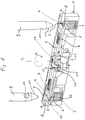
- Fig. 1 shows a lock body 1, which with two essentially cylindrical bracket receptacles 2 is provided.
- the driver locking element 15 is drawn in a position where it is inserted Bracket 9 is located. The position also corresponds to Bolt 6 and the driver 12 of the operating position in the Lock body 1 locked bracket 9, in which the driver 12 the bolt 6 blocked.
- the ironing agents 3, 4 are in a position in which they are from Lock body 1 released bracket 9 come to rest.
- each Bracket contact disc 4 is provided, which is essentially Has an annular shape.
- bracket contact disks are 4 on one provided in the bracket receptacles 2 Flange 5 on, which prevents compression spring 3 and bracket contact disc 4 out of the designated area the bracket holder 2 can move out.
- the bending angle is here 180 °.
- the bent ends of the bolt 6 ensure that in the locking position in the bracket receptacles 2 projecting area of the latch 6 has a rounded end area 8, which in the manner already explained the insertion of the temple ends in the bracket receptacles 2 facilitated.
- Fig. 1 the end regions are above the bracket receptacles 2 shown a bracket 9, which is circular in cross section is.
- Both temple ends each have a recess 10, wherein both recesses 10 each on the inside of the bracket 9 are arranged.
- the recesses 10 are complementary to the end regions the latch 6 is formed so that in the recesses 10 End regions of the bolt 6 in their locking position can come to lie.
- the end region of the Temple 9 is each frustoconical, wherein the lateral surface of this frustoconical area displacement surface 11 according to the invention for actuating the Latch 6 forms.
- the driver 12 is by a in Fig. 1 for the sake of Clarity, not shown, lock cylinder actuated and rotatable about the axis C.
- the C axis extends parallel to the ends of the bracket 9 and to the longitudinal axes the bracket recordings 2.
- the driver 12 has one on its narrow sides Blocking surface 13 in the position shown in Fig. 1 a movement of the latch 6 from the locked position impossible in the unlocked position.
- driver locking element 15 provided below one of the two bolts 6 , which in Fig. 1 in that position is drawn in which it is in the bracket recordings 2 locked bracket would be located.
- the driver locking element 15 is by a not shown Biased compression spring in the direction of arrow D and points to his lying in the area of the bracket receptacle 2 End an eyelet-shaped opening 16, which is dimensioned so that the temple ends moved through this opening 16 can be.
- the driver blocking element 15 At its end facing away from the opening 16 is the driver blocking element 15 provided with a blocking area 17, which when the driver locking element is moved in the direction of arrow D. the driver 13 in its shown in Fig. 1 Holds position.
- U-lock In the locked position of the invention shown in Fig. 2 U-lock is the shackle 9 with its two Ends 11 inserted into the lock body 1.
- the rounded end regions 8 of the bars 6 engage in the in the locking position shown in Fig. 2 in the recesses 10 of the two bow ends 9 and lock onto them Way the bracket 9 in the lock body 1. An undesirable movement the bolt 6 from the recesses 10 is through the driver in its locked position 12 blocked.
- the position of the driver 12 according to FIG. 2 corresponds to the position shown in FIG. 1.
- the position of the driver blocking element also corresponds 15 of FIG. 2 of the position shown in FIG. 1, so that the driver 12 in the locking position shown in Fig. 2 not by the driver locking element 15 blocked, but freely movable against its bias is. So the lock can be made by means of a in Fig. 2 Key not shown for reasons of clarity be unlocked by using the key mentioned the driver 12, for example by 90 ° in an open position can be twisted.
- the driver 12 is compared to that shown in Fig. 1 and 2 position rotated by 90 °, whereby the Driver 12, the two driver tabs 14 linear in one Moves that the latch 6 counter to that by the compression springs 7 caused bias from the recesses 10 of the Bracket 9 are moved out.
- FIG 3 shows the position of the lock according to the invention, after the bracket 9 is released from the lock body 1 and the key from the not shown, with the driver 12 in The active lock cylinder has been removed. This position can be called the standby position will.
- the bolts 6 are in their locking position, are however - since they are by the carrier 12 are not blocked - can be moved into their unlocked position.
- the driver 12 is in the standby position compared to its position shown in Fig. 1 by approximately 45 ° rotated counterclockwise and is driven by the driver locking element 15 held in this position.
- the bracket contact disks 4 are in the in Fig. 3rd position shown in its upper stop position, in which they rest on the respective flange 5.
- the bracket 9 is in turn inserted into the lock body 1, the bars 6 by the mutual contact of their rounded end regions 8 and the displacement surfaces 11 of the bracket 9 moved into their unlocked position.
- the displacement surface 11 causes the left Temple end, which in the opening 16 of the driver locking element 15 penetrates, a displacement of the driver locking element in the position shown in Figs. 1 and 2, in the the driver 12 is movable against its bias, so that it is by means of the key or the locking cylinder is acted upon.
Landscapes
- Lock And Its Accessories (AREA)
Abstract
Description
- Fig. 1
- eine perspektivische Ansicht eines erfindungsgemäß aufgebauten Schloßkörpers und erfindungsgemäß einsetzbarer Bügelenden,
- Fig. 2
- die Ansicht einer geöffneten Gehäusehälfte eines Schlosses gemäß Fig. 1 in der Verriegelungsstellung, und
- Fig. 3
- eine Ansicht gemäß Fig. 2 in einer geöffneten Bereitschaftsstellung des Schlosses.
Claims (16)
- Bügelschloß, insbesondere Zweiradschloß, mit einem Schloßkörper (1) und einem in diesem bei abgezogenem Schlüssel verriegelbaren Bügel (9), wobei die beiden Bügelenden in der Verriegelungsstellung in jeweils einer Bügelaufnahme (2) gehalten sind und zumindest ein Bügelende mittels eines in eine im Endbereich des Bügels vorgesehene Ausnehmung (10) eingreifenden Riegels (6) verriegelbar ist,
dadurch gekennzeichnet,daß die Riegel (6) in ihrer Verriegelungsstellung durch ein Blockierelement (12) blockiert sind. - Bügelschloß nach Anspruch 1,
dadurch gekennzeichnet,daß die Riegel (6) durch einen mittels eines Schließzylinders beaufschlagbaren Mitnehmer (12) in ihre Entriegelungsstellung bewegbar sind. - Bügelschloß nach Anspruch 2,
dadurch gekennzeichnet,daß das Blockierelement durch den in der Verriegelungsstellung befindlichen Mitnehmer (12) gebildet ist. - Bügelschloß nach einem der vorhergehenden Ansprüche,
dadurch gekennzeichnet,daß die Riegel (6) in ihre Verriegelungsstellung vorgespannt sind. - Bügelschloß nach einem der Ansprüche 2 bis 4,
dadurch gekennzeichnet,daß der Mitnehmer (12) insbesondere mittels einer Spiralfeder in seine Verriegelungsstellung vorgespannt ist. - Bügelschloß nach einem der Ansprüche 2 bis 5,
dadurch gekennzeichnet,daß ein Mitnehmer-Sperrelement (15) vorgesehen ist, welches die Mitnehmer (12) bei vom Schloßkörper (1) gelöstem Bügel (9) entgegen seiner Vorspannung in der Entriegelungsstellung hält. - Bügelschloß nach Anspruch 6,
dadurch gekennzeichnet,daß das Mitnehmer-Sperrelement (15) in die den Mitnehmer (12) in seiner Entriegelungsstellung haltende Position vorgespannt ist. - Bügelschloß nach einem der Ansprüche 6 oder 7,
dadurch gekennzeichnet,daß ein Bügelende eine Verdrängungsfläche (11) zum Bewegen des Mitnehmer-Sperrelements (15) entgegen seiner Vorspannung aufweist. - Bügelschloß nach einem der vorhergehenden Ansprüche,
dadurch gekennzeichnet,daß in den Bügelaufnahmen (2) jeweils unter Vorspannung stehende Bügelbeaufschlagungsmittel (3, 4) vorgesehen sind, mittels derer der vom Schloßkörper vollständig lösbare Bügel (9) beim mit dem Schlüssel auslösbaren Entriegelungsvorgang aus den Bügelaufnahmen (2) herausbewegbar ist. - Bügelschloß nach Anspruch 9,
dadurch gekennzeichnet,daß die Bügelbeaufschlagungsmittel jeweils aus einer mit einer Druckfeder (3) gekoppelten Bügel-Kontaktscheibe (4) bestehen. - Bügelschloß nach einem der vorhergehenden Ansprüche,
dadurch gekennzeichnet,daß zumindest das die Ausnehmung (10) aufweisende Bügelende mit einer Verdrängungsfläche (11) zum während des Einführens des Bügelendes in die Bügelaufnahme (2) erfolgenden Bewegen des Riegels (6) in seine Öffnungsstellung versehen ist. - Bügelschloß nach Anspruch 11,
dadurch gekennzeichnet,daß die Riegel (6) an ihrem den Bügelaufnahmen (2) zugewandten Endbereich an die Verdrängungsfläche (11) der Bügelenden angepaßte, insbesondere abgerundete Kontaktflächen (8) aufweisen. - Bügelschloß nach Anspruch 12,
dadurch gekennzeichnet,daß die Kontaktflächen (8) durch die umgebogenen Enden des in diesem Bereich streifenförmigen Riegelmaterials gebildet sind. - Bügelschloß nach einem der vorhergehenden Ansprüche,
dadurch gekennzeichnet,daß alle Verdrängungsflächen (11) durch eine kegelstumpfförmige Ausformung der Bügelenden gebildet sind. - Bügelschloß nach einem der vorhergehenden Ansprüche,
dadurch gekennzeichnet,saß alle beweglichen Teile, insbesondere die Bügelbeaufschlagungsmittel (3, 4), die Riegel (6), der Mitnehmer (12) und das Mitnehmer-Sperrelement (15) unter Vorspannung stehen. - Bügelschloß nach einem der vorhergehenden Ansprüche,
dadurch gekennzeichnet,daß in einer Verriegelungsstellung der Riegel (6) in die Ausnehmung (10) des Bügels (9) eingreift und mittels des Blockierelements (12) blockiert ist,daß in einer Öffnungsstellung bei entgegen einer Federkraft bewegtem Schlüssel der Riegel (6) aus der Ausnehmung (10) des Bügels (9) bzw. aus der jeweiligen Bügelaufnahme (2) zurückgezogen ist, unddaß in einer Bereitschaftsstellung bei vom Schloßkörper (1) gelöstem Bügel (9) der Riegel (6) in die jeweilige Bügelaufnahme (2) hineinragt und dabei vom Blockierelement (12) freigegeben ist.
Applications Claiming Priority (2)
| Application Number | Priority Date | Filing Date | Title |
|---|---|---|---|
| DE19638188A DE19638188A1 (de) | 1996-09-18 | 1996-09-18 | Bügelschloß |
| DE19638188 | 1996-09-18 |
Publications (2)
| Publication Number | Publication Date |
|---|---|
| EP0831198A1 true EP0831198A1 (de) | 1998-03-25 |
| EP0831198B1 EP0831198B1 (de) | 2003-03-26 |
Family
ID=7806093
Family Applications (1)
| Application Number | Title | Priority Date | Filing Date |
|---|---|---|---|
| EP97115634A Expired - Lifetime EP0831198B1 (de) | 1996-09-18 | 1997-09-09 | Bügelschloss |
Country Status (2)
| Country | Link |
|---|---|
| EP (1) | EP0831198B1 (de) |
| DE (2) | DE19638188A1 (de) |
Cited By (2)
| Publication number | Priority date | Publication date | Assignee | Title |
|---|---|---|---|---|
| DE102007035122A1 (de) * | 2007-07-27 | 2009-01-29 | ABUS August Bremicker Söhne KG | Schloss |
| EP3591147A1 (de) * | 2018-07-06 | 2020-01-08 | ABUS August Bremicker Söhne KG | Zweiradschloss mit alarmfunktion |
Families Citing this family (6)
| Publication number | Priority date | Publication date | Assignee | Title |
|---|---|---|---|---|
| FR2982302B1 (fr) * | 2011-11-09 | 2014-11-07 | Thirard Ets | Verrou electromecanique |
| DE102013114055B4 (de) * | 2013-12-13 | 2016-02-04 | Sheng Yung Lock Industrial Co., Ltd. | Schloss mit einem trennbaren Riegel |
| WO2015192013A1 (en) * | 2014-06-12 | 2015-12-17 | Schlage Lock Company Llc | Hoop lock with dual locking |
| CN112539004B (zh) * | 2020-12-10 | 2023-01-31 | 潘永旺 | U型锁 |
| DE102021122247A1 (de) | 2021-08-27 | 2023-03-02 | ABUS August Bremicker Söhne Kommanditgesellschaft | Elektromechanisches Schloss |
| DE102023116135A1 (de) | 2023-06-20 | 2024-12-24 | ABUS August Bremicker Söhne Kommanditgesellschaft | Klobenschloss |
Citations (5)
| Publication number | Priority date | Publication date | Assignee | Title |
|---|---|---|---|---|
| US2433114A (en) * | 1945-10-22 | 1947-12-23 | Illinois Lock Co | Padlock |
| US4621509A (en) * | 1983-10-20 | 1986-11-11 | Kabushiki Kaisha Saikousha | Combination locking device having removable U-shaped retaining rod |
| EP0550412A2 (de) * | 1988-05-06 | 1993-07-07 | Aug. Winkhaus GmbH & Co. KG | Langbügelschloss |
| US5394712A (en) * | 1994-01-11 | 1995-03-07 | Nigostar Industry Co., Ltd. | Motorcycle lock |
| NL9401601A (nl) * | 1994-09-29 | 1996-05-01 | Chen Kuei Hsieh | U-vormig hangslot. |
Family Cites Families (4)
| Publication number | Priority date | Publication date | Assignee | Title |
|---|---|---|---|---|
| DE9013187U1 (de) * | 1990-09-17 | 1991-05-23 | Aug. Winkhaus GmbH & Co KG, 4404 Telgte | Bügelschloß mit Schwenkverrriegelung |
| DE4329511A1 (de) * | 1993-09-01 | 1995-03-02 | Winkhaus Fa August | Langbügelschloß mit selbsthemmender Verklemmung eines Riegelelements |
| US5417092A (en) * | 1994-06-02 | 1995-05-23 | Iu; Chien-Chzh | Padlock |
| DE29520227U1 (de) * | 1995-12-20 | 1996-02-29 | Rerlly Industry Co., Ltd., Jen Te Hsiang, Tainan | Schloß, insbesondere für Motorräder |
-
1996
- 1996-09-18 DE DE19638188A patent/DE19638188A1/de not_active Withdrawn
-
1997
- 1997-09-09 DE DE59709608T patent/DE59709608D1/de not_active Expired - Fee Related
- 1997-09-09 EP EP97115634A patent/EP0831198B1/de not_active Expired - Lifetime
Patent Citations (5)
| Publication number | Priority date | Publication date | Assignee | Title |
|---|---|---|---|---|
| US2433114A (en) * | 1945-10-22 | 1947-12-23 | Illinois Lock Co | Padlock |
| US4621509A (en) * | 1983-10-20 | 1986-11-11 | Kabushiki Kaisha Saikousha | Combination locking device having removable U-shaped retaining rod |
| EP0550412A2 (de) * | 1988-05-06 | 1993-07-07 | Aug. Winkhaus GmbH & Co. KG | Langbügelschloss |
| US5394712A (en) * | 1994-01-11 | 1995-03-07 | Nigostar Industry Co., Ltd. | Motorcycle lock |
| NL9401601A (nl) * | 1994-09-29 | 1996-05-01 | Chen Kuei Hsieh | U-vormig hangslot. |
Cited By (6)
| Publication number | Priority date | Publication date | Assignee | Title |
|---|---|---|---|---|
| DE102007035122A1 (de) * | 2007-07-27 | 2009-01-29 | ABUS August Bremicker Söhne KG | Schloss |
| US8127577B2 (en) | 2007-07-27 | 2012-03-06 | Abus August Bremicker Soehne Kg | Lock |
| EP3591147A1 (de) * | 2018-07-06 | 2020-01-08 | ABUS August Bremicker Söhne KG | Zweiradschloss mit alarmfunktion |
| CN110685513A (zh) * | 2018-07-06 | 2020-01-14 | Abus·奥古斯特·布莱梅克·索恩有限股份两合公司 | 具有警报功能的两轮车锁 |
| CN110685513B (zh) * | 2018-07-06 | 2022-04-26 | Abus·奥古斯特·布莱梅克·索恩有限股份两合公司 | 具有警报功能的两轮车锁 |
| US11447976B2 (en) | 2018-07-06 | 2022-09-20 | ABUS August Bremicker Söhne KG | Two-wheeler lock having an alarm function |
Also Published As
| Publication number | Publication date |
|---|---|
| EP0831198B1 (de) | 2003-03-26 |
| DE19638188A1 (de) | 1998-03-19 |
| DE59709608D1 (de) | 2003-04-30 |
Similar Documents
| Publication | Publication Date | Title |
|---|---|---|
| DE3906473C2 (de) | Schließverriegelung | |
| DE2942789C2 (de) | Permutationsschloß | |
| WO2002029185A1 (de) | Werkzeug zum entsperren eines schliesszylinders | |
| EP0369107A2 (de) | Zylinderschloss | |
| DE3144829C2 (de) | Vorrichtung zum Neueinstellen des Schlüsselgeheimnisses in einem Permutationsschloß | |
| DE2441463C3 (de) | Zylinderschlofi mit einem axial verschiebbaren Zylinderkern, insbesondere für ein Lenkschloß in Kraftfahrzeugen | |
| DE4408024C5 (de) | Sicherheitsschalter | |
| DE2914088C2 (de) | Sperrvorrichtung für einen von Hand betätigbaren Schalthebel | |
| EP1171895B1 (de) | Sperrvorrichtung für schaltgeräte | |
| EP0831198B1 (de) | Bügelschloss | |
| DE3126761A1 (de) | Permutationsschloss | |
| DE3126751C2 (de) | Vorrichtung zum Neueinstellen des Schlüsselgeheimnisses in einem Permutationsschloß für Koffer oder dergleichen | |
| DE102011050226A1 (de) | Dispositif de commande de verrouillage pour vantail | |
| DE3717778C2 (de) | ||
| EP1637679A1 (de) | Bügelschloss, insbesondere Zweiradschloss | |
| EP2993090B1 (de) | Lenkradverriegelung | |
| DE69909676T2 (de) | Lenkradschlossvorrrichtung für eine Fahrzeuglenkung | |
| EP0434922B1 (de) | Aufnahmebehälter für Magnetbandkassette | |
| DE202007016091U1 (de) | Treibstangenschloss | |
| EP0428029B1 (de) | Schliesseinrichtung | |
| DE2322330C3 (de) | Kraftfahrzeug-Lenkschloß | |
| CH671603A5 (de) | ||
| EP0553412A1 (de) | Drehriegel | |
| DE3421094A1 (de) | Sicherheitsschloss | |
| DE2321246A1 (de) | Mangetisch betaetigbares schloss |
Legal Events
| Date | Code | Title | Description |
|---|---|---|---|
| PUAI | Public reference made under article 153(3) epc to a published international application that has entered the european phase |
Free format text: ORIGINAL CODE: 0009012 |
|
| AK | Designated contracting states |
Kind code of ref document: A1 Designated state(s): DE FR NL SE |
|
| AX | Request for extension of the european patent |
Free format text: AL;LT;LV;RO;SI |
|
| 17P | Request for examination filed |
Effective date: 19980902 |
|
| AKX | Designation fees paid |
Free format text: DE FR NL SE |
|
| RBV | Designated contracting states (corrected) |
Designated state(s): DE FR NL SE |
|
| 17Q | First examination report despatched |
Effective date: 20010831 |
|
| GRAH | Despatch of communication of intention to grant a patent |
Free format text: ORIGINAL CODE: EPIDOS IGRA |
|
| GRAH | Despatch of communication of intention to grant a patent |
Free format text: ORIGINAL CODE: EPIDOS IGRA |
|
| GRAA | (expected) grant |
Free format text: ORIGINAL CODE: 0009210 |
|
| AK | Designated contracting states |
Designated state(s): DE FR NL SE |
|
| REF | Corresponds to: |
Ref document number: 59709608 Country of ref document: DE Date of ref document: 20030430 Kind code of ref document: P |
|
| REG | Reference to a national code |
Ref country code: SE Ref legal event code: TRGR |
|
| PGFP | Annual fee paid to national office [announced via postgrant information from national office to epo] |
Ref country code: NL Payment date: 20030917 Year of fee payment: 7 |
|
| PGFP | Annual fee paid to national office [announced via postgrant information from national office to epo] |
Ref country code: FR Payment date: 20030918 Year of fee payment: 7 |
|
| PGFP | Annual fee paid to national office [announced via postgrant information from national office to epo] |
Ref country code: SE Payment date: 20030923 Year of fee payment: 7 |
|
| PGFP | Annual fee paid to national office [announced via postgrant information from national office to epo] |
Ref country code: DE Payment date: 20031016 Year of fee payment: 7 |
|
| ET | Fr: translation filed | ||
| PLBE | No opposition filed within time limit |
Free format text: ORIGINAL CODE: 0009261 |
|
| STAA | Information on the status of an ep patent application or granted ep patent |
Free format text: STATUS: NO OPPOSITION FILED WITHIN TIME LIMIT |
|
| 26N | No opposition filed |
Effective date: 20031230 |
|
| PG25 | Lapsed in a contracting state [announced via postgrant information from national office to epo] |
Ref country code: SE Free format text: LAPSE BECAUSE OF NON-PAYMENT OF DUE FEES Effective date: 20040910 |
|
| PG25 | Lapsed in a contracting state [announced via postgrant information from national office to epo] |
Ref country code: NL Free format text: LAPSE BECAUSE OF NON-PAYMENT OF DUE FEES Effective date: 20050401 Ref country code: DE Free format text: LAPSE BECAUSE OF NON-PAYMENT OF DUE FEES Effective date: 20050401 |
|
| EUG | Se: european patent has lapsed | ||
| PG25 | Lapsed in a contracting state [announced via postgrant information from national office to epo] |
Ref country code: FR Free format text: LAPSE BECAUSE OF NON-PAYMENT OF DUE FEES Effective date: 20050531 |
|
| NLV4 | Nl: lapsed or anulled due to non-payment of the annual fee |
Effective date: 20050401 |
|
| REG | Reference to a national code |
Ref country code: FR Ref legal event code: ST |