EP0831200A2 - Poignée de verrou - Google Patents
Poignée de verrou Download PDFInfo
- Publication number
- EP0831200A2 EP0831200A2 EP97850131A EP97850131A EP0831200A2 EP 0831200 A2 EP0831200 A2 EP 0831200A2 EP 97850131 A EP97850131 A EP 97850131A EP 97850131 A EP97850131 A EP 97850131A EP 0831200 A2 EP0831200 A2 EP 0831200A2
- Authority
- EP
- European Patent Office
- Prior art keywords
- handle
- joint
- locking
- striking
- piston element
- Prior art date
- Legal status (The legal status is an assumption and is not a legal conclusion. Google has not performed a legal analysis and makes no representation as to the accuracy of the status listed.)
- Withdrawn
Links
Images


Classifications
-
- B—PERFORMING OPERATIONS; TRANSPORTING
- B62—LAND VEHICLES FOR TRAVELLING OTHERWISE THAN ON RAILS
- B62D—MOTOR VEHICLES; TRAILERS
- B62D33/00—Superstructures for load-carrying vehicles
- B62D33/02—Platforms; Open load compartments
- B62D33/023—Sideboard or tailgate structures
- B62D33/027—Sideboard or tailgate structures movable
- B62D33/037—Latching means therefor
-
- E—FIXED CONSTRUCTIONS
- E05—LOCKS; KEYS; WINDOW OR DOOR FITTINGS; SAFES
- E05C—BOLTS OR FASTENING DEVICES FOR WINGS, SPECIALLY FOR DOORS OR WINDOWS
- E05C19/00—Other devices specially designed for securing wings, e.g. with suction cups
- E05C19/10—Hook fastenings; Fastenings in which a link engages a fixed hook-like member
- E05C19/12—Hook fastenings; Fastenings in which a link engages a fixed hook-like member pivotally mounted around an axis
- E05C19/14—Hook fastenings; Fastenings in which a link engages a fixed hook-like member pivotally mounted around an axis with toggle action
Definitions
- the present invention relates to a latch handle which forms a connecting means between an openable element, e.g., a pivotable or displaceable cover, and a fixed element, e.g., a platform corner post of a lorry, which handle is pivotable mounted in a joint and extends in locking position between the pivotable and the fixed elements and pivots during idle away from one of these two elements
- an openable element e.g., a pivotable or displaceable cover
- a fixed element e.g., a platform corner post of a lorry
- Latch handles can be used for maneuvering a mechanism with the aid of which the ends of a platform boardscan be secured at a respective corner post.
- This mechanism usually comprises a number of parts and is thus expensive to manufacture.
- At covers or boards of vehicles transporting cargo it is desireable to be able to lock said covers or boards in a secure way in order to avoid unintentional opening thereof. This would otherwise lead to both personal and material damages.
- locking pins, wires, or the like which are thread through a loop at the handle and in this way locks this visavi opening. This known solution is, however, circumstantial to use and there is a risk that pins are lost during handling.
- One object of the present invention is to obtain a locking device which cost efficient in manufacturing and is simple to handle.
- the present invention is characterized in that a bolt means which is connected to the latch handle via a joint and which is influenced by a spring member, which bolt means cooperates with a striking-plate means in the locking position of the handle, whereby an imaginary line through the joint of the bolt means of the handle and a contact point of the bolt means in the striking-plate passes by the joint of the latch handle during maneuvering of the latch handle from an idle position to locking position.
- the latch handle of the invention has been described in the following as being attached to a specific area of use for the locking of a platform board to a corner post, but several other fields of use are of course contemplated.
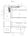
- the lorry platform 10 shown in Fig. 1 in a broken view is provided with a holding means 11, which cooperates with the edge side of a platform board 12 to form a hinged joint.
- This joint fascilitates the lowering of the board between the position shown where the board abuts a vertical corner post 13, and a lowered position which fascilitates loading and unloading of goods unto the platform.
- Locking, and maneuvering, respectively, of the board 12 is carried out by means of a handle 14 mounted in the respective corner post 13, which handle is pivotably mounted in a joint 15 at the upper end of the corner post.
- the joint comprises a shaft extending perpendicular to the longitudinal direction of the corner post and furthermore, perpendicular to the pivoting axis of the board.
- the handle In locking position the handle extends in a right angle to the corner post into a upwardly opened channel in the platform board abutting the corner post.
- the platform board 12 is set free from the corner post 13 by pivoting the handle 14 upwardly, out of the channel/channels.
- the handle 10 is influenced by a compression spring 16, which acts to keep the handle either in the locking position shown in Fig. 1, or in an open position, substantially in line with the corner post.
- the spring 16 is connected to the handle 14 via a pivoting shaft 17.
- the pivoting shaft 17 is present on one side of the joint shaft 15 when the handle is situated in the locking position shown in Fig. 1 and on the other side when the handle is situated in the open position.
- the compression spring 16 will first become compressed and then again become decompressed so that the handle becomes self-locking.
- the compression spring 16 is thread onto a rod 18 which is pivotably mounted with its one end in the pivoting shaft 17, and which is displaceable with its opposite end in a hollow opening in the corner post 13.
- the handle 10 is U-shaped and is provided with an extra, blocking device being placed between the two side legs, which blocking device operates independently from the compression spring 16.
- the blocking device comprises a piston 19, which is connected via a joint 20 to the handle and is provided with a compression spring 21.
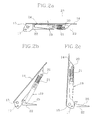
- the piston cooperates with a striking-plate 22 in the locking position of the handle, whereby the imagined line 23 of Fig. 2a, which extends through the joint 20 of the piston of the handle and the contact point 24 of the piston of the striking-plate 22, passes by the joint 15 of the latch hanlde during the maneuvering of the handle from an idle position to the locking position of board 12.
- the geometry provides for an efficient over-the-centre locking of the blocking device which locking occurs already at a pivoting angle of about 15 to 20° the locking position shown in Fig. 2a, which means that the handle is "drawn" down into a stable locking position.
- Fig. 3a-c shows the striking-plate 22 being substantially U-shaped with upwardly taperingside walls 26 in Fig. 3 on each side of the ramp surface 25.
- the contact point consists of a perpendicular bridge part which connects both side walls 26.
- the ramp side of the striking-plate is provided with two holes 27 for mounting screws, not shown.
- the piston comprises two parts 28, 29 of which one part 29 forms the joint of the handle 10.
- the other part 28 is telescopically displaceably mounted at the first part via a cylindrical bore 30 which cooperates with a piston part 31 of the part 29.
- This piston part 31 forms the bearing for the compression spring 21.
- the two parts are connected by means of a perpendicular pin 32 which is fixedly connected to the piston part 31.
- the pin is displaceably mounted in oval slots 33 of the second part.
- a cross surface 34 at the free end of the part 28 is arranged to cooperate with the bridge part 24 of the srtiking-plate 22.
- the handle 14 exerts a pressure action on the striking-plate in the locking position via the piston 19, which provides for a reduction of the play between the corner post and the platform board. Normally, a considerable play can occur at removable corner posts and this play would create a problem at the corner of the platform, which problem thus is avoided by the catching up at the piston 19 as decribed above.
- the piston 19 can be manufactured as one integral part, which is both pivotable and displaceably mounted at the latch ahndle via an oval slot, whereby the spring can act between a journal formed by the joint 20 and a perpendicular surface on the piston 19.
- the handle having the above described blocking means can be mounted in the displaceable board in stead of the fixed corner post.
Landscapes
- Engineering & Computer Science (AREA)
- Mechanical Engineering (AREA)
- Chemical & Material Sciences (AREA)
- Combustion & Propulsion (AREA)
- Transportation (AREA)
- Lock And Its Accessories (AREA)
- Steering Devices For Bicycles And Motorcycles (AREA)
Applications Claiming Priority (2)
| Application Number | Priority Date | Filing Date | Title |
|---|---|---|---|
| SE9603394 | 1996-09-18 | ||
| SE9603394A SE507093C2 (sv) | 1996-09-18 | 1996-09-18 | Låshandtag |
Publications (2)
| Publication Number | Publication Date |
|---|---|
| EP0831200A2 true EP0831200A2 (fr) | 1998-03-25 |
| EP0831200A3 EP0831200A3 (fr) | 1998-04-01 |
Family
ID=20403924
Family Applications (1)
| Application Number | Title | Priority Date | Filing Date |
|---|---|---|---|
| EP97850131A Withdrawn EP0831200A3 (fr) | 1996-09-18 | 1997-09-15 | Poignée de verrou |
Country Status (2)
| Country | Link |
|---|---|
| EP (1) | EP0831200A3 (fr) |
| SE (1) | SE507093C2 (fr) |
Cited By (1)
| Publication number | Priority date | Publication date | Assignee | Title |
|---|---|---|---|---|
| EP2389053A1 (fr) * | 2010-05-19 | 2011-11-23 | Harris Corporation | Ensemble de loquet, tirage inversé surcentré |
Family Cites Families (5)
| Publication number | Priority date | Publication date | Assignee | Title |
|---|---|---|---|---|
| FR957071A (fr) * | 1950-02-14 | |||
| US1827319A (en) * | 1930-05-31 | 1931-10-13 | Excelsior Hardware Co | Hasp for trunk locks |
| FR1079841A (fr) * | 1953-02-27 | 1954-12-02 | Sncaso | Dispositif de fixation rapide pour éléments démontables |
| FR1485188A (fr) * | 1966-06-30 | 1967-06-16 | Dispositif de fermeture pour ridelles rabattables de camions et de remorques | |
| US3526423A (en) * | 1968-05-03 | 1970-09-01 | Rex Chainbelt Inc | Toggle latch with preloaded drawhook |
-
1996
- 1996-09-18 SE SE9603394A patent/SE507093C2/sv not_active IP Right Cessation
-
1997
- 1997-09-15 EP EP97850131A patent/EP0831200A3/fr not_active Withdrawn
Cited By (2)
| Publication number | Priority date | Publication date | Assignee | Title |
|---|---|---|---|---|
| EP2389053A1 (fr) * | 2010-05-19 | 2011-11-23 | Harris Corporation | Ensemble de loquet, tirage inversé surcentré |
| US8360487B2 (en) | 2010-05-19 | 2013-01-29 | Harris Corporation | Latch assembly, over-center reverse draw |
Also Published As
| Publication number | Publication date |
|---|---|
| SE9603394L (sv) | 1998-03-19 |
| SE9603394D0 (sv) | 1996-09-18 |
| EP0831200A3 (fr) | 1998-04-01 |
| SE507093C2 (sv) | 1998-03-30 |
Similar Documents
| Publication | Publication Date | Title |
|---|---|---|
| EP0464334B1 (fr) | Elément de verrouillage pour bloquer des colis dans une soute à fret d'avion | |
| US7231695B2 (en) | Apparatus for automatically locking the ship container | |
| US6050467A (en) | Article carrier assembly having a cross rail assembly adjustable within a range of infinite operating positions | |
| US6974164B2 (en) | Latch device for securing cargo containers | |
| EP1096086A2 (fr) | Serrure de porte, notamment pour tracteurs | |
| CA1163865A (fr) | Dispositif d'arrimage de conteneurs sur wagons | |
| DE10392914T5 (de) | Entfernt betätigte Freigabegriff-Verriegelung | |
| CA1166897A (fr) | Dispositif d'arrimage de conteneurs sur wagons | |
| EP1268311A1 (fr) | Element de liaison a verrouillage et liberation automatiques pour raccorder deux elements de structure dont au moins un presente un trou accrochable par l'arriere | |
| EP0831200A2 (fr) | Poignée de verrou | |
| US6490766B1 (en) | Coupling device including automatic latching lock | |
| US5174456A (en) | Shell door locking device | |
| HUT78066A (hu) | Konténerrögzítő eszköz | |
| DE29616344U1 (de) | Hängerunge | |
| US20010035113A1 (en) | Stackable pallet | |
| KR20010030566A (ko) | 적재편 및 콘테이너를 적재하기 위한 방법 | |
| US5636889A (en) | Flat hook with spring loaded lock-pin | |
| DE3244086A1 (de) | Riegelverschluss | |
| US4400121A (en) | Railway car hitch for a trailer | |
| DE19628433A1 (de) | Klappbare Abschlußvorrichtung eines Schiebeverdecks | |
| US6773213B1 (en) | Cargo tie down in a vehicle | |
| US4645160A (en) | Cam operated locking device | |
| WO2000030895A1 (fr) | Systeme de transport de charges pour vehicules | |
| KR20010027303A (ko) | 화물차의 적재함 캐치 어셈블리 | |
| DE69204758T2 (de) | Runge für eine Ladefläche und Methode zum Montieren einer Schliess- und Beeinflussungsvorrichtung in dieser. |
Legal Events
| Date | Code | Title | Description |
|---|---|---|---|
| PUAI | Public reference made under article 153(3) epc to a published international application that has entered the european phase |
Free format text: ORIGINAL CODE: 0009012 |
|
| PUAL | Search report despatched |
Free format text: ORIGINAL CODE: 0009013 |
|
| AK | Designated contracting states |
Kind code of ref document: A2 Designated state(s): DE ES FR GB IT NL |
|
| AX | Request for extension of the european patent |
Free format text: AL;LT;LV;RO;SI |
|
| AK | Designated contracting states |
Kind code of ref document: A3 Designated state(s): AT BE CH DE DK ES FI FR GB GR IE IT LI LU MC NL PT SE |
|
| AX | Request for extension of the european patent |
Free format text: AL;LT;LV;RO;SI |
|
| 17P | Request for examination filed |
Effective date: 19981001 |
|
| AKX | Designation fees paid |
Free format text: DE ES FR GB IT NL |
|
| RBV | Designated contracting states (corrected) |
Designated state(s): DE ES FR GB IT NL |
|
| STAA | Information on the status of an ep patent application or granted ep patent |
Free format text: STATUS: THE APPLICATION IS DEEMED TO BE WITHDRAWN |
|
| 18D | Application deemed to be withdrawn |
Effective date: 20000401 |