EP0831250A2 - Actuateur linéaire - Google Patents
Actuateur linéaire Download PDFInfo
- Publication number
- EP0831250A2 EP0831250A2 EP97307244A EP97307244A EP0831250A2 EP 0831250 A2 EP0831250 A2 EP 0831250A2 EP 97307244 A EP97307244 A EP 97307244A EP 97307244 A EP97307244 A EP 97307244A EP 0831250 A2 EP0831250 A2 EP 0831250A2
- Authority
- EP
- European Patent Office
- Prior art keywords
- lead screw
- extension tube
- linear actuator
- nut
- tube assembly
- Prior art date
- Legal status (The legal status is an assumption and is not a legal conclusion. Google has not performed a legal analysis and makes no representation as to the accuracy of the status listed.)
- Withdrawn
Links
- 239000000463 material Substances 0.000 claims description 9
- 229910000906 Bronze Inorganic materials 0.000 claims description 4
- 239000010974 bronze Substances 0.000 claims description 4
- KUNSUQLRTQLHQQ-UHFFFAOYSA-N copper tin Chemical compound [Cu].[Sn] KUNSUQLRTQLHQQ-UHFFFAOYSA-N 0.000 claims description 4
- 239000004033 plastic Substances 0.000 claims description 4
- 229920003023 plastic Polymers 0.000 claims description 4
- 239000004677 Nylon Substances 0.000 description 6
- 229920001778 nylon Polymers 0.000 description 6
- 229910000831 Steel Inorganic materials 0.000 description 4
- XAGFODPZIPBFFR-UHFFFAOYSA-N aluminium Chemical compound [Al] XAGFODPZIPBFFR-UHFFFAOYSA-N 0.000 description 4
- POIUWJQBRNEFGX-XAMSXPGMSA-N cathelicidin Chemical compound C([C@@H](C(=O)N[C@@H](CCCNC(N)=N)C(=O)N[C@@H](CCCCN)C(=O)N[C@@H](CO)C(=O)N[C@@H](CCCCN)C(=O)N[C@@H](CCC(O)=O)C(=O)N[C@@H](CCCCN)C(=O)N[C@@H]([C@@H](C)CC)C(=O)NCC(=O)N[C@@H](CCCCN)C(=O)N[C@@H](CCC(O)=O)C(=O)N[C@@H](CC=1C=CC=CC=1)C(=O)N[C@@H](CCCCN)C(=O)N[C@@H](CCCNC(N)=N)C(=O)N[C@@H]([C@@H](C)CC)C(=O)N[C@@H](C(C)C)C(=O)N[C@@H](CCC(N)=O)C(=O)N[C@@H](CCCNC(N)=N)C(=O)N[C@@H]([C@@H](C)CC)C(=O)N[C@@H](CCCCN)C(=O)N[C@@H](CC(O)=O)C(=O)N[C@@H](CC=1C=CC=CC=1)C(=O)N[C@@H](CC(C)C)C(=O)N[C@@H](CCCNC(N)=N)C(=O)N[C@@H](CC(N)=O)C(=O)N[C@@H](CC(C)C)C(=O)N[C@@H](C(C)C)C(=O)N1[C@@H](CCC1)C(=O)N[C@@H](CCCNC(N)=N)C(=O)N[C@@H]([C@@H](C)O)C(=O)N[C@@H](CCC(O)=O)C(=O)N[C@@H](CO)C(O)=O)NC(=O)[C@H](CC=1C=CC=CC=1)NC(=O)[C@H](CC(O)=O)NC(=O)CNC(=O)[C@H](CC(C)C)NC(=O)[C@@H](N)CC(C)C)C1=CC=CC=C1 POIUWJQBRNEFGX-XAMSXPGMSA-N 0.000 description 4
- 229920006324 polyoxymethylene Polymers 0.000 description 4
- 239000010959 steel Substances 0.000 description 4
- 229910052782 aluminium Inorganic materials 0.000 description 3
- 230000013011 mating Effects 0.000 description 3
- 230000002441 reversible effect Effects 0.000 description 3
- HCHKCACWOHOZIP-UHFFFAOYSA-N Zinc Chemical compound [Zn] HCHKCACWOHOZIP-UHFFFAOYSA-N 0.000 description 2
- 239000011354 acetal resin Substances 0.000 description 2
- -1 but not limited to Substances 0.000 description 2
- 239000011295 pitch Substances 0.000 description 2
- XLYOFNOQVPJJNP-UHFFFAOYSA-N water Substances O XLYOFNOQVPJJNP-UHFFFAOYSA-N 0.000 description 2
- 229910052725 zinc Inorganic materials 0.000 description 2
- 239000011701 zinc Substances 0.000 description 2
- DHKHKXVYLBGOIT-UHFFFAOYSA-N 1,1-Diethoxyethane Chemical compound CCOC(C)OCC DHKHKXVYLBGOIT-UHFFFAOYSA-N 0.000 description 1
- 229910000838 Al alloy Inorganic materials 0.000 description 1
- 229910001229 Pot metal Inorganic materials 0.000 description 1
- 229910001297 Zn alloy Inorganic materials 0.000 description 1
- 239000000853 adhesive Substances 0.000 description 1
- 230000001070 adhesive effect Effects 0.000 description 1
- 229910045601 alloy Inorganic materials 0.000 description 1
- 239000000956 alloy Substances 0.000 description 1
- 238000010276 construction Methods 0.000 description 1
- 239000000356 contaminant Substances 0.000 description 1
- 238000002788 crimping Methods 0.000 description 1
- 230000001419 dependent effect Effects 0.000 description 1
- 239000000428 dust Substances 0.000 description 1
- 239000002783 friction material Substances 0.000 description 1
- 239000011521 glass Substances 0.000 description 1
- 229920001903 high density polyethylene Polymers 0.000 description 1
- 239000004700 high-density polyethylene Substances 0.000 description 1
- 239000003562 lightweight material Substances 0.000 description 1
- 229920001684 low density polyethylene Polymers 0.000 description 1
- 239000004702 low-density polyethylene Substances 0.000 description 1
- 238000005461 lubrication Methods 0.000 description 1
- 239000007769 metal material Substances 0.000 description 1
- 229920000915 polyvinyl chloride Polymers 0.000 description 1
- 239000004800 polyvinyl chloride Substances 0.000 description 1
- 230000001681 protective effect Effects 0.000 description 1
- 230000000452 restraining effect Effects 0.000 description 1
- 239000010935 stainless steel Substances 0.000 description 1
- 229910001220 stainless steel Inorganic materials 0.000 description 1
Images



Classifications
-
- F—MECHANICAL ENGINEERING; LIGHTING; HEATING; WEAPONS; BLASTING
- F16—ENGINEERING ELEMENTS AND UNITS; GENERAL MEASURES FOR PRODUCING AND MAINTAINING EFFECTIVE FUNCTIONING OF MACHINES OR INSTALLATIONS; THERMAL INSULATION IN GENERAL
- F16H—GEARING
- F16H25/00—Gearings comprising primarily only cams, cam-followers and screw-and-nut mechanisms
- F16H25/18—Gearings comprising primarily only cams, cam-followers and screw-and-nut mechanisms for conveying or interconverting oscillating or reciprocating motions
- F16H25/20—Screw mechanisms
-
- F—MECHANICAL ENGINEERING; LIGHTING; HEATING; WEAPONS; BLASTING
- F16—ENGINEERING ELEMENTS AND UNITS; GENERAL MEASURES FOR PRODUCING AND MAINTAINING EFFECTIVE FUNCTIONING OF MACHINES OR INSTALLATIONS; THERMAL INSULATION IN GENERAL
- F16H—GEARING
- F16H25/00—Gearings comprising primarily only cams, cam-followers and screw-and-nut mechanisms
- F16H25/18—Gearings comprising primarily only cams, cam-followers and screw-and-nut mechanisms for conveying or interconverting oscillating or reciprocating motions
- F16H25/20—Screw mechanisms
- F16H2025/2031—Actuator casings
-
- F—MECHANICAL ENGINEERING; LIGHTING; HEATING; WEAPONS; BLASTING
- F16—ENGINEERING ELEMENTS AND UNITS; GENERAL MEASURES FOR PRODUCING AND MAINTAINING EFFECTIVE FUNCTIONING OF MACHINES OR INSTALLATIONS; THERMAL INSULATION IN GENERAL
- F16H—GEARING
- F16H25/00—Gearings comprising primarily only cams, cam-followers and screw-and-nut mechanisms
- F16H25/18—Gearings comprising primarily only cams, cam-followers and screw-and-nut mechanisms for conveying or interconverting oscillating or reciprocating motions
- F16H25/20—Screw mechanisms
- F16H2025/2062—Arrangements for driving the actuator
- F16H2025/2084—Perpendicular arrangement of drive motor to screw axis
-
- F—MECHANICAL ENGINEERING; LIGHTING; HEATING; WEAPONS; BLASTING
- F16—ENGINEERING ELEMENTS AND UNITS; GENERAL MEASURES FOR PRODUCING AND MAINTAINING EFFECTIVE FUNCTIONING OF MACHINES OR INSTALLATIONS; THERMAL INSULATION IN GENERAL
- F16H—GEARING
- F16H25/00—Gearings comprising primarily only cams, cam-followers and screw-and-nut mechanisms
- F16H25/18—Gearings comprising primarily only cams, cam-followers and screw-and-nut mechanisms for conveying or interconverting oscillating or reciprocating motions
- F16H25/20—Screw mechanisms
- F16H2025/2062—Arrangements for driving the actuator
- F16H2025/209—Arrangements for driving the actuator using worm gears
-
- F—MECHANICAL ENGINEERING; LIGHTING; HEATING; WEAPONS; BLASTING
- F16—ENGINEERING ELEMENTS AND UNITS; GENERAL MEASURES FOR PRODUCING AND MAINTAINING EFFECTIVE FUNCTIONING OF MACHINES OR INSTALLATIONS; THERMAL INSULATION IN GENERAL
- F16H—GEARING
- F16H25/00—Gearings comprising primarily only cams, cam-followers and screw-and-nut mechanisms
- F16H25/18—Gearings comprising primarily only cams, cam-followers and screw-and-nut mechanisms for conveying or interconverting oscillating or reciprocating motions
- F16H25/20—Screw mechanisms
- F16H25/22—Screw mechanisms with balls, rollers, or similar members between the co-operating parts; Elements essential to the use of such members
- F16H25/2204—Screw mechanisms with balls, rollers, or similar members between the co-operating parts; Elements essential to the use of such members with balls
-
- Y—GENERAL TAGGING OF NEW TECHNOLOGICAL DEVELOPMENTS; GENERAL TAGGING OF CROSS-SECTIONAL TECHNOLOGIES SPANNING OVER SEVERAL SECTIONS OF THE IPC; TECHNICAL SUBJECTS COVERED BY FORMER USPC CROSS-REFERENCE ART COLLECTIONS [XRACs] AND DIGESTS
- Y10—TECHNICAL SUBJECTS COVERED BY FORMER USPC
- Y10T—TECHNICAL SUBJECTS COVERED BY FORMER US CLASSIFICATION
- Y10T74/00—Machine element or mechanism
- Y10T74/18—Mechanical movements
- Y10T74/18568—Reciprocating or oscillating to or from alternating rotary
- Y10T74/18576—Reciprocating or oscillating to or from alternating rotary including screw and nut
- Y10T74/18688—Limit stop
-
- Y—GENERAL TAGGING OF NEW TECHNOLOGICAL DEVELOPMENTS; GENERAL TAGGING OF CROSS-SECTIONAL TECHNOLOGIES SPANNING OVER SEVERAL SECTIONS OF THE IPC; TECHNICAL SUBJECTS COVERED BY FORMER USPC CROSS-REFERENCE ART COLLECTIONS [XRACs] AND DIGESTS
- Y10—TECHNICAL SUBJECTS COVERED BY FORMER USPC
- Y10T—TECHNICAL SUBJECTS COVERED BY FORMER US CLASSIFICATION
- Y10T74/00—Machine element or mechanism
- Y10T74/18—Mechanical movements
- Y10T74/18568—Reciprocating or oscillating to or from alternating rotary
- Y10T74/18576—Reciprocating or oscillating to or from alternating rotary including screw and nut
- Y10T74/18712—Contamination related
- Y10T74/1872—Imperforate enclosure
Definitions
- This invention relates in general to linear actuators and in particular to an improved structure for a linear actuator which is relatively lightweight and inexpensive in construction, yet which is capable of handling relatively heavy loads.
- a linear actuator is a device which is used to cause linear movement, typically reciprocating linear movement, of a workpiece along a desired path of movement.
- a typical linear actuator includes an electric motor having a rotatable output shaft. The output shaft of the electric motor is connected through a gear train to a nut and lead screw mechanism. Rotation of the output shaft of the electric motor causes corresponding rotation of the lead screw.
- the nut has an opening formed therethrough having an internal thread.
- the lead screw extends through the opening and has an external thread formed which cooperates with the internal thread formed on the nut.
- the nut is mounted on the lead screw in such a manner as to be restrained from rotating with the lead screw when the lead screw rotates. As a result, rotation of the lead screw causes linear movement of the nut axially along the lead screw. The direction of such axial movement of the nut (and the workpiece connected thereto) is dependent upon the direction of rotation of the lead screw.
- Linear actuators are widely used in a variety of applications ranging from small to heavy loads. To accommodate heavy loads, known linear actuator structures have been formed from relatively large and heavy metallic components. Consequently, linear actuator structures currently in use are relatively heavy and expensive. Thus, it would be desirable to provide an improved linear actuator structure which is relatively lightweight and inexpensive to produce, and yet which is capable of handling heavy loads.
- the above object as well as other objects not specifically enumerated are achieved by an improved structure for a linear actuator in which the rotary motion from a motor is converted to rotary motion of a lead screw by use of a worm gear drive train.
- the rotary motion of the lead screw is converted to linear motion of an extension tube by use of a nut which is threadedly mounted on the lead screw.
- the linear actuator includes a motor having a rotatable output shaft, and the lead screw has a forward end and a rear end.
- a worm gear drive train connected between the motor output shaft and the lead screw converts the rotary motion of the motor output shaft into rotary motion of the lead screw.
- An extension tube assembly is mounted at the forward end of the lead screw for movement axially of the lead screw and for engaging the workpiece or device to be moved linearly.
- the extension tube assembly includes an extension tube concentrically disposed around the forward end of the lead screw.
- the extension tube has a forward end for contacting a device requiring linear motion, and a rear end.
- a nut is connected to the rear end of the extension tube and is threadedly mounted on the lead screw so that rotation of the lead screw moves the nut and the extension tube assembly axially along the lead screw.
- a mounting adapter is positioned at the rear end of the lead screw for rotatably mounting the lead screw. The mounting adapter also attaches the linear actuator to the support structure, such as a frame or machine.
- the linear actuator preferably includes a housing to cover the linear actuator for protection from dirt and for maintaining lubrication.
- the housing is mounted on the mounting adapter, and substantially all of the axial forces along the lead screw are transmitted through the mounting adapter and not through the housing. All the large axial and radial forces are transmitted through and applied to the lead screw, the extension tube assembly, and the mounting adapter. Therefore, the housing which encloses the linear actuator can be made from a lightweight material, such as plastic.
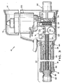
- the illustrated linear actuator 10 includes a hollow housing 11 for protectively enclosing most of the components thereof to prevent the entry of dirt, water, and other contaminants from the environment.
- the housing 11 includes a main housing portion 12.
- a rear panel 14 is connected to the rear open end of the main housing portion 12, while an elongated hollow cover tube 16 extends forwardly from a forward opening formed through the main housing portion 12.
- the forward end of the cover tube 16 is closed by an end cap 18.
- the end cap 18 has an opening 20 formed therethrough, for a purpose which will be described below.
- the main housing portion, the rear panel, the cover tube, and the end cap are preferably formed from a relatively lightweight, rigid material.
- these components may be formed from glass-filled nylon, aluminum, zinc, aluminum/zinc alloys, stainless steel, polyvinyl chloride, high or low density polyethylene.
- the linear actuator 10 includes a source of rotational power, such as an electric motor 22 having a rotatable output shaft or worm gear drive shaft 24.
- the motor 22 can be of any type depending on the type of application in which the linear actuator 10 is to be used.
- the electrical motor may be a 12 volt or 24 volt direct current, reversible motor.
- the motor may be a 115 volt or 230 volt alternating current, reversible motor.
- the output shaft 24 of the electric motor 22 is formed having an integral external helical thread.
- the output shaft of the motor is connected to a worm gear drive train 26.
- the worm gear drive train 26 connects the output shaft 24 to the lead screw 30, thereby causing the lead screw to be rotated at a desired speed.
- the speed at which the lead screw is rotated can be varied by changing the gear ratio in the worm gear drive train 26.
- a single gear ratio is used and the speed at which the lead screw is rotated is varied by using interchangeable lead screws having different pitches.
- the rotational motion of the lead screw 30 is converted into linear motion by means of an extension tube assembly 32.
- the extension tube assembly 32 is mounted on the forward end 34 of the lead screw 30 for reciprocal or axial movement with respect to the lead screw.
- the extension tube assembly 32 is comprised of a nut 36 which is threaded and mounted on the lead screw, and an extension tube 40 concentrically disposed around the forward end 34 of the lead screw.
- the nut 36 is positioned at the rear end 42 of the extension tube, and is prevented from rotating with the lead screw because the nut has a square-shaped nut head 44, and the cover tube 16 is square-shaped so that it fits tightly around the nut head 44 to prevent the nut from rotating with the lead screw.
- the nut instead of rotating the nut moves axially along the lead screw so as to be extended from the cover tube 16 or retracted into the cover tube 16.
- An alternative way to prevent the rotation of the nut 36 is to use other shapes for the nut head 44 and the cover tube, including any generally rectangular shape.
- the nut can be fixed to the cover tube with some device, such as a ball bearing screw, which allows a single range of movement for the nut, which is to move axially along a screw.
- the nut also includes front face 46 on cylindrical body 48.
- the nut can be constructed from a variety of plastic or metal materials including, but not limited to, nylon, acetal resin (polyacetals), bronze, and steel. In a preferred embodiment, the nut is made from nylon.
- the lead screw 30 is of involute form (i.e. having inwardly curved threads) and functions as a worm form of gearing that engages with mating threads on the nut 36 to produce linear motion.
- the lead screw is preferably made from steel, but can be made from other suitable materials including, but not limited to, aluminum.
- the nut 36 is connected to the generally cylindrically-shaped extension tube 40 by fastening the extension tube to the cylindrical body 48 of the nut in some fashion.
- the extension tube is made from a deformable, usually metallic, material such as steel tubing which allows the extension tube to be crimped around the cylindrical body 48 of the nut.
- a front stop 54 At the forward end 50 of the extension tube is a front stop 54 and a front adapter 56.
- the front adapter 56 is a cylindrically-shaped plug having a knurled surface 58 at one end and a bore 60 which extends perpendicularly through the front adapter 56 at the opposite end.
- a grooved or necked portion 64 is located between the knurled surface 58 and the bore 60.
- the bore is used for attaching or connecting the workpiece or device, not shown, requiring the linear motion, to the linear actuator 10.
- a lockable pin is inserted through the bore to attach the front of the adapter 56 to the device requiring the linear motion.
- the diameter of the bore is within the range of from about 0.25 to about 0.50 inches to accommodate the many devices that can be moved or actuated using the linear actuator of the invention. In a preferred embodiment, the bore diameter is within the range of from about 0.25 to about 0.375 inches.
- the front adapter 56 can be made from a variety of materials including, but not limited to, steel, aluminum, zinc, or alloys thereof. In a preferred embodiment, the front adapter is made from die-cast zinc. The front adapter is fixed in place within the extension tube 40 by crimping the extension tube around the front adapter in the grooved portion 64 and on the knurled surface 58 of the front adapter.
- an end stop 66 On the forward end 34 of the lead screw 30 is an end stop 66.
- the end stop is an annular element which is mounted on the lead screw by mating threads, and it is fixed in position with a cross pin 68.
- the cross pin is inserted into aligned bores, not shown, in both the end stop and the lead screw.
- the end stop 66 is sized to fit closely within the extension tube 40 so that it supports the lead screw 30 at its forward end 34.
- the end stop 66 is made from a material having a low coefficient of friction such as nylon.
- the front stop 54 mounted on the front adapter 56, is used to provide a physical hard stop with low friction for the extension tube assembly 32 when the extension tube assembly is fully retracted into the cover tube 16, at which point the front stop abuts the end stop 66 mounted on the lead screw 30.
- the front stop 54 is a relatively thin disk which abuts the end of the front adapter 56 having the knurled surface 58.
- the front stop 54 may be secured to the front adapter 56 using any of the known devices including, but not limited to, adhesive, rivets, and screws.
- the front stop 54 is made from a material having a low coefficient of friction such as nylon.
- the extension tube assembly 32 is able to move axially along the lead screw 30 in both a forward or extend direction, wherein the extension tube assembly 30 moves away from the motor 22, and in a rearward or retract direction wherein the extension tube assembly moves towards the motor and the rearward end of the actuator 10.
- Axial movement in the extend direction is stopped when the front face 46 of the nut 36 abuts the end stop 66 mounted on the lead screw 30.
- the axial movement of the extension tube assembly 32 in the retract direction is stopped when the front adapter 56 abuts the end stop 66.
- the front face 46 of the nut, the front stop 54, and the end stop 66 are all made from a material having a low coefficient of friction, such as nylon.
- the use of a material having a low coefficient of friction for these components is desirable so as to allow the lead screw 30 to reverse its rotation under high axial loads when the extension tube is at the end of either its extend or retract stroke.
- other low friction materials could be used including, but not limited to, acetal resins (polyacetals) or bronze.
- the total amount of axial movement or stroke length provided by the extension tube assembly 32 can be designed in varying lengths. In general, the stroke length of the extension tube assembly is usually within the range of from about one to about thirty inches.
- the lead screw 30 is supported within the extension tube 40 by the end stop 66 and the nut 36.
- the extension tube assembly 32 and lead screw are supported within the generally square-shaped cover tube 16 by the generally square-shaped nut head 44 and by the cover tube end cap 18.
- the cover tube end cap has an aperture 20 through which the extension tube 40 is extended and retracted. Located adjacent the aperture 20 are two annular-shaped recesses, not shown, for receiving two O-rings, not shown which wipe against the extension tube, and provide protection against dirt, dust and water.
- the worm gear drive train 26 is comprised of a wonn drive shaft 24 having an axis which is disposed at a 90 degree angle to the axis of a driven worm gear 70 such that the axis of the worm drive shaft 24 and driven worm gear 70 are non-parallel.
- the worm drive shaft 24 is connected to the motor 22 and meshingly engages the driven worm gear 70 which is fixedly mounted on the lead screw 30.
- the rotation of the driven worm gear 70 by the worm drive shaft 24 causes the lead screw 30 to be rotated at a desired speed.
- the speed at which the lead screw is rotated can be varied by changing the gear ratio between the worm drive and the driven worm gear. However, in a preferred embodiment, a single gear ratio is used and the speed at which the lead screw is rotated is varied by using interchangeable lead screws having different pitches.
- the lead screw 30 is also supported near the middle of the linear actuator 10 by a mounting bracket 74 which is connected to the outside diameter of the lead screw 30 through a bushing, not shown, and bearing, not shown.
- the mounting bracket 74 also supports the motor 22, the worm gear drive shaft 24, and several other elements, as will be explained below. Therefore, the mounting bracket 74 functions to locate the gear center distances of the worm gear 70 and to maintain the necessary gear backlash to each other and between the gears and the lead screw 30.
- the lead screw is also supported by the driven worm gear 70 and the rear mounting adapter, indicated generally at 80, both of which are mounted on the lead screw 30.
- the rear mounting adapter 80 includes a ball bearing unit, indicated generally at 82, a bearing plate 84, and a rear mount, indicated generally at 86.
- Ball bearing unit 82 includes an outer race 88, an inner race 90, and roller balls 92 which are disposed between the inner race and outer race.
- bronze or plastic bushings could be used in place of the ball bearing 81 to carry the axial and radial loads.
- the rear mount 86 is used for securing the linear actuator 10 to any suitable support.
- the rear mount 86 has a cylindrically shaped body 96 with a central cavity 98 in which the ball bearing unit 82 and lead screw 30 are disposed.
- the ball bearing unit 82 is mounted on the lead screw 30 and is fixed in place by a cross pin 100.
- Cross pin 100 extends through a bore 102 in the lead screw and abuts one side of the ball bearing unit 82.
- On the other side of the ball bearing unit is the bearing plate 84.
- Bearing plate abuts the outer race 88 of the ball bearing unit and is fixed to the body 96 of the rear mount 86 by threaded bolts 104 or other fastening devices.
- On the rearward end of the rear mount 86 is a mounting bore 106 which extends perpendicularly through the rear adapter 86 and can be used for accepting a pin that will attach the linear actuator 10 to the desired support. Any other suitable mounting configuration can be used.
- the inner race 90 of the ball bearing unit 82 abuts a hub portion 110 of the driven worm gear 70.
- Driven worm gear 70 is fixed in position on the lead screw 30 through the use of a cross pin 112 and a bore 114.
- the cross pin 112 is received in an annular shaped recess 116 of the driven worm gear 70.
- machined journals are not used to support the lead screw 30. Instead as described above, substantially all axial loads-are resolved or transmitted, including end stop rotational load of the lead screw, by the three cross pins 68, 100 and 112 which fix the position of the end stop 66, the driven worm gear 70, and the ball bearing unit 82 respectively, on the lead screw 30. In addition, all axial thrust forces are contained along the center line of the lead screw and resolved at the ball bearing unit 82, rear mount 86 and the front adapter 56. Therefore, no thrust loads, or at most insubstantial thrust loads, are transmitted to the housing 11.
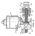
- the lead screw 30 is also used to operate two limit switches 120 and 122 and a positional encoder-potentiometer 124 using helical gearing. More specifically, as shown in Fig. 6, helical gears 126 and 128 are driven by the lead screw to operate limit switches 120 and 122, respectively, while helical gear 130 is driven by the lead screw to drive the positional-encoder potentiometer 124.
- the positional-encoder potentiometer is used to provide feedback control and/or indication with respect to the position of the extension tube assembly 32. The potentiometer operates by a change in resistance corresponding to a change in axial position of the actuator.
- the limit switches 120 and 122 are used to stop the motor from rotating in its current direction when the number of revolutions of the lead screw corresponds to a predetermined point of travel of the extension tube assembly 32. More specifically, one of the limit switches 120 may be used to stop the motor when the extension tube assembly has been fully extended, as indicated by the front face 46 of the nut 36 abutting the end stop 66. The other limit switch 122 may be used to stop the motor when the extension tube assembly is fully retracted, as indicated by the front stop 54 abutting the end stop 66. Alternatively, these limit switches could be used to stop the motor at any point of travel of the extension tube assembly. For definition purposes only, limit switch 120 will be designated as the extend stop limit switch while limit switch 122 will be designated as the retract stop limit switch.
- contact cams 132 and 134 having mating threads are mounted on limit switch shafts 136 and 138, respectively.
- Each contact cam 132 and 134 has a finger-like portion which is captured in a slot 140 found in the support bracket 74. Only one slot 140 is shown in Fig. 7, but another slot is used to capture contact cam 134 such that the contact cams 132 and 134 are prevented from rotating with their respective limit switch shafts 136 and 138. Instead, the contact cams 132 and 134 move axially along the limit switch shafts 136 and 138, respectively, as these shafts turn.
- the mounting bracket 74 supports the positional encoder-potentiometer 124 and the two position limit switches 120 and 122.
- the positional encoder-potentiometer 124 and the position limit switches 120 and 122 are connected through helical gearing to the lead screw. Therefore, the support bracket 74 functions to locate the gear center distances of the worm gear 70, the gearing for the positional encoder-potentiometer 124, and the limit switches 120 and 122 so as to maintain the necessary gear backlash to each other and between the gears and the lead screw 30.
Landscapes
- Engineering & Computer Science (AREA)
- General Engineering & Computer Science (AREA)
- Mechanical Engineering (AREA)
- Transmission Devices (AREA)
- Connection Of Motors, Electrical Generators, Mechanical Devices, And The Like (AREA)
Applications Claiming Priority (2)
| Application Number | Priority Date | Filing Date | Title |
|---|---|---|---|
| US718878 | 1996-09-24 | ||
| US08/718,878 US5809833A (en) | 1996-09-24 | 1996-09-24 | Linear actuator |
Publications (2)
| Publication Number | Publication Date |
|---|---|
| EP0831250A2 true EP0831250A2 (fr) | 1998-03-25 |
| EP0831250A3 EP0831250A3 (fr) | 1999-03-03 |
Family
ID=24887920
Family Applications (1)
| Application Number | Title | Priority Date | Filing Date |
|---|---|---|---|
| EP97307244A Withdrawn EP0831250A3 (fr) | 1996-09-24 | 1997-09-18 | Actuateur linéaire |
Country Status (2)
| Country | Link |
|---|---|
| US (1) | US5809833A (fr) |
| EP (1) | EP0831250A3 (fr) |
Cited By (22)
| Publication number | Priority date | Publication date | Assignee | Title |
|---|---|---|---|---|
| WO2002029284A1 (fr) * | 2000-10-03 | 2002-04-11 | Linak A/S | Actionneur lineaire |
| EP1273247A1 (fr) * | 2001-07-05 | 2003-01-08 | Dewert Antriebs- und Systemtechnik GmbH & Co. KG | Entraínement à moteur électrique |
| EP1100183A3 (fr) * | 1999-11-11 | 2003-07-02 | Dewert Antriebs- und Systemtechnik GmbH & Co. KG | Dispositif d'actionnement à moteur électrique |
| EP1840311A1 (fr) * | 2006-03-31 | 2007-10-03 | Valeo Sicherheitssysteme GmbH | Mécanisme de reglage a broche linéaire |
| WO2007112744A1 (fr) * | 2006-03-30 | 2007-10-11 | Linak A/S | Actionneur linéaire |
| WO2009086831A1 (fr) * | 2008-01-12 | 2009-07-16 | Linak A/S | Actionneur linéaire |
| DE212008000062U1 (de) | 2007-09-27 | 2010-12-23 | Linak A/S | Linearantrieb |
| EP1701063A4 (fr) * | 2003-12-24 | 2011-05-11 | Mitsuba Corp | Verin lineaire |
| WO2011057632A1 (fr) | 2009-11-13 | 2011-05-19 | Linak A/S | Actionneur linéaire |
| US8001861B2 (en) | 2007-10-10 | 2011-08-23 | Parker-Hannifin Corporation | High force electro-mechanical actuator |
| WO2012028122A1 (fr) * | 2010-08-31 | 2012-03-08 | Kiekert Aktiengesellschaft | Unité de régulation pour applications en technique automobile |
| WO2013076557A1 (fr) * | 2011-11-21 | 2013-05-30 | Kongsberg Automotive Ab | Ensemble vérin linéaire |
| EP2789491A1 (fr) * | 2013-04-12 | 2014-10-15 | Hyundai Wia Corporation | Embrayage de type déconnecteur pour dispositif entraîné par une roue arrière dans un véhicule électrique à quatre roues motrices |
| WO2016015731A3 (fr) * | 2014-07-29 | 2016-06-02 | Linak A/S | Actionneur linéaire |
| US9492960B2 (en) | 2011-11-23 | 2016-11-15 | Synventive Molding Solutions, Inc. | Non-coaxially mounted electric actuator and transmission |
| CN106121402A (zh) * | 2008-02-15 | 2016-11-16 | 开开特股份公司 | 机动车门锁 |
| KR20170013992A (ko) * | 2014-06-04 | 2017-02-07 | 롤스 로이스 아베 | 파킹 위치 |
| WO2019137588A1 (fr) | 2018-01-11 | 2019-07-18 | Linak A/S | Actionneur linéaire |
| WO2019218154A1 (fr) * | 2018-05-15 | 2019-11-21 | 炼马机电(东莞)有限公司 | Dispositif d'entraînement linéaire |
| EP1618313B1 (fr) * | 2003-04-30 | 2020-12-02 | Goodrich Corporation | Frein electrique destine a un aeronef |
| US10899056B2 (en) | 2011-11-23 | 2021-01-26 | Synventive Molding Solutions, Inc. | Non-coaxially mounted electric actuator and transmission |
| US11512765B2 (en) | 2017-02-13 | 2022-11-29 | Linak A/S | Linear actuator |
Families Citing this family (58)
| Publication number | Priority date | Publication date | Assignee | Title |
|---|---|---|---|---|
| US6276050B1 (en) * | 1998-07-20 | 2001-08-21 | Emhart Inc. | Riveting system and process for forming a riveted joint |
| US9015920B2 (en) | 1997-07-21 | 2015-04-28 | Newfrey Llc | Riveting system and process for forming a riveted joint |
| US5988328A (en) * | 1998-03-17 | 1999-11-23 | Dana Corporation | Spring set centrifugally released brake |
| US6168120B1 (en) * | 1998-10-05 | 2001-01-02 | Western-Cullen-Hayes, Inc. | Operator for a railroad implement |
| US6244686B1 (en) * | 1999-04-23 | 2001-06-12 | Xerox Corporation | Print head drive mechanism |
| US6259175B1 (en) | 1999-11-18 | 2001-07-10 | Dana Corporation | Linear actuator |
| US6540658B1 (en) | 2000-05-30 | 2003-04-01 | Abiomed, Inc. | Left-right flow control algorithm in a two chamber cardiac prosthesis |
| US6527698B1 (en) | 2000-05-30 | 2003-03-04 | Abiomed, Inc. | Active left-right flow control in a two chamber cardiac prosthesis |
| US6879065B2 (en) * | 2001-04-10 | 2005-04-12 | International Business Machines Corporation | Linear actuator |
| GB0116674D0 (en) * | 2001-07-07 | 2001-08-29 | Lucas Industries Ltd | Screw actuator |
| US6910263B2 (en) * | 2001-12-25 | 2005-06-28 | Newfrey Llc | Self-piercing rivet setting apparatus and system |
| CN1607983A (zh) * | 2001-12-27 | 2005-04-20 | 纽飞利有限公司 | 自动穿孔铆钉连接装置及该连接装置用的冲模 |
| CN100488410C (zh) * | 2003-02-13 | 2009-05-20 | 德沃特传动及系统科技有限公司 | 电动直线驱动装置 |
| US7040056B2 (en) * | 2004-03-24 | 2006-05-09 | Dubose Monty C | Gear shaft assembly |
| US20050284026A1 (en) * | 2004-06-25 | 2005-12-29 | Dubose Monty C | Shutter drive and lock assembly |
| US7146786B2 (en) * | 2004-07-27 | 2006-12-12 | Dennis Brandon | Electric linear deck lift assembly |
| DE112005002663B4 (de) * | 2004-10-26 | 2021-12-30 | Stoneridge Control Devices, Inc. | Aktuator und Fahrzeugsystem mit einem solchen Aktuator |
| US20070029142A1 (en) * | 2005-08-03 | 2007-02-08 | Drennen David B | Brake system including ball screw and nut assembly |
| US7770961B2 (en) * | 2006-02-20 | 2010-08-10 | Magna Closures Inc. | Compact cable drive power sliding door mechanism |
| US20090100951A1 (en) * | 2006-03-30 | 2009-04-23 | Linak A/S | Linear Actuator with Potentiometer |
| US20080028878A1 (en) * | 2006-08-07 | 2008-02-07 | Chia-Jung Wang | Lifting Device having Double Screw Rods |
| KR101467422B1 (ko) | 2007-08-06 | 2014-12-01 | 스트라텍 파워 액세스 엘엘씨 | 가동 차량 패널용 선형 구동 액추에이터 |
| US8113076B2 (en) * | 2008-08-07 | 2012-02-14 | Itt Manufacturing Enterprises, Inc. | Mechanical positioner for reclining seat assembly |
| US20100186529A1 (en) * | 2009-01-27 | 2010-07-29 | Hiwin Mikrosystem Corp. | Linear actuator |
| US8256313B2 (en) * | 2009-02-27 | 2012-09-04 | Stoneridge Control Devices, Inc. | Actuator with linearly movable drive screw |
| DK176963B1 (da) * | 2009-05-01 | 2010-08-02 | Linak As | Lineær aktuator med positionsbestemmelsessystem |
| EP2289797B1 (fr) * | 2009-08-27 | 2011-11-02 | Eurocopter Deutschland GmbH | Train d'atterrissage escamotable pour giravion |
| WO2011037989A2 (fr) | 2009-09-24 | 2011-03-31 | Goshichi, Llc | Elévateur de fauteuil roulant pour véhicule |
| CN102667246B (zh) | 2009-11-13 | 2016-03-23 | 利纳克有限公司 | 线性致动器 |
| CN201619097U (zh) * | 2010-01-11 | 2010-11-03 | 付俊杰 | 一种多功能电动工具 |
| JP4769899B2 (ja) * | 2010-01-15 | 2011-09-07 | Thk株式会社 | 防塵機構付きリニアアクチュエータ |
| GB201001178D0 (en) * | 2010-01-26 | 2010-03-10 | Airbus Operations Ltd | Linear actuator |
| GB201001175D0 (en) * | 2010-01-26 | 2010-03-10 | Airbus Operations Ltd | Aircraft steering actuator |
| RU2561023C2 (ru) * | 2010-08-31 | 2015-08-20 | Киекерт Акциенгезельшафт | Исполнительный механизм для автотехнического применения |
| US8978356B2 (en) * | 2010-12-03 | 2015-03-17 | The Boeing Company | Thrust reverser and variable area fan nozzle actuation system and method |
| AU2012275088A1 (en) * | 2011-06-29 | 2014-01-30 | Compressor Products International Llc | Lubricator pump adjuster |
| KR101271509B1 (ko) * | 2011-09-08 | 2013-06-05 | 주식회사 만도 | 전자 기계식 브레이크 |
| DE102011116631A1 (de) * | 2011-10-20 | 2013-04-25 | Robert Bosch Gmbh | Linearbewegungsvorrichtung mit einer Verdrehsicherung, umfassend einen langgestreckten Gleitbelag |
| US8794087B2 (en) * | 2012-06-08 | 2014-08-05 | Timotion Technology Co., Ltd. | Gear motor having safety mechanism |
| US9500476B2 (en) * | 2012-07-27 | 2016-11-22 | Waterman Industries, Llc | Linear position monitoring system |
| US9027220B2 (en) | 2012-08-07 | 2015-05-12 | Newfrey Llc | Rivet setting machine |
| JP5855547B2 (ja) * | 2012-08-27 | 2016-02-09 | Ntn株式会社 | 電動リニアアクチュエータ |
| US8791663B2 (en) * | 2012-10-19 | 2014-07-29 | Robotzone, Llc | Hobby servo motor linear actuator systems |
| TWI503496B (zh) * | 2013-05-23 | 2015-10-11 | Timotion Technology Co Ltd | 具有位置檢出機構的電動缸 |
| US10370897B2 (en) * | 2015-02-25 | 2019-08-06 | Munchkin, Inc. | Linear actuator extension for barrier assembly |
| CN106965168A (zh) * | 2016-01-13 | 2017-07-21 | 大银微系统股份有限公司 | 工业机器人 |
| WO2017177238A2 (fr) * | 2016-04-08 | 2017-10-12 | Munchkin, Inc. | Mécanisme d'extension à ajustement par pression de grille de barrière |
| TWM540215U (zh) * | 2017-01-13 | 2017-04-21 | Timotion Technology Co Ltd | 往復式線性推桿 |
| CN107339031B (zh) * | 2017-07-14 | 2019-09-06 | 绍兴市上虞永生汽车部件有限公司 | 一种上锁驱动执行装置 |
| JP6512388B1 (ja) * | 2017-10-19 | 2019-05-15 | 日本精工株式会社 | 伸縮リンク及びサスペンション |
| TWM561150U (zh) * | 2018-03-05 | 2018-06-01 | Moteck Electric Corp | 電動推桿之結構改良 |
| DE102018214601B4 (de) * | 2018-08-29 | 2026-04-30 | Schaeffler Technologies AG & Co. KG | System zum Erfassen der Position einer Lineareinheit eines Linearsystems |
| DE102019105560A1 (de) * | 2019-03-05 | 2020-09-10 | Ewellix AB | Linearantrieb |
| GB2582976B (en) * | 2019-04-12 | 2023-12-06 | Zf Automotive Uk Ltd | A steering column assembly for a vehicle |
| US11752867B2 (en) * | 2019-04-15 | 2023-09-12 | Bg Intellectuals, Inc. | Device for revving an engine of a vehicle |
| DE202019103358U1 (de) * | 2019-06-14 | 2020-09-15 | Dewertokin Gmbh | Linearantrieb |
| US12221821B2 (en) * | 2021-09-29 | 2025-02-11 | U-Shin Deutschland Zugangssysteme Gmbh | Drive for a flap |
| USD1075603S1 (en) | 2022-10-21 | 2025-05-20 | Bg Intellectuals, Inc. | Pedal actuator |
Family Cites Families (19)
| Publication number | Priority date | Publication date | Assignee | Title |
|---|---|---|---|---|
| GB592735A (en) * | 1945-05-31 | 1947-09-26 | B & P Swift Ltd | Improvements relating to linear actuating mechanisms |
| US2398841A (en) * | 1943-03-01 | 1946-04-23 | John K Morris | Gear power unit |
| US3798983A (en) * | 1972-05-15 | 1974-03-26 | W Smith | Adaptable gear housing for linear actuator construction |
| US3951004A (en) * | 1974-03-20 | 1976-04-20 | International Telephone & Telegraph Corporation | Multiple position seat adjustment mechanism |
| CA1078884A (fr) * | 1977-03-16 | 1980-06-03 | Jean Masclet | Methode d'amortissement oleomecanique des chocs et des vibrations sur une charge |
| US4318304A (en) * | 1980-04-11 | 1982-03-09 | Sundstrand Corporation | Force limiting device |
| US4602520A (en) * | 1983-06-23 | 1986-07-29 | Aisin Seiki Kabushiki Kaisha | Telescopic steering column assembly |
| JPS60196462A (ja) * | 1984-03-21 | 1985-10-04 | Aisin Seiki Co Ltd | ネジ式駆動装置のガタ除去機構 |
| JPS61105358A (ja) * | 1984-10-30 | 1986-05-23 | Aisin Seiki Co Ltd | テレスコピツク装置 |
| US4858481A (en) * | 1985-05-13 | 1989-08-22 | Brunswick Valve & Control, Inc. | Position controlled linear actuator |
| US4712441A (en) * | 1985-05-13 | 1987-12-15 | Brunswick Valve & Control, Inc. | Position controlled linear actuator |
| IT210468Z2 (it) * | 1987-01-21 | 1988-12-30 | Iveco Fiat | Attuatore lineare elettromeccanico per il ribaltamento della cabina di guida di un veicolo industriale |
| US5090513A (en) * | 1990-12-24 | 1992-02-25 | Amigo Mobility International, Inc. | Powered wheeled vehicle for the handicapped and others desiring assistance incorporating automatically locking swivelable and raiseable powered seat |
| US5388471A (en) * | 1993-10-12 | 1995-02-14 | Alliedsignal Inc. | Thrust bearing for an actuator driving a sensor device |
| US5461935A (en) * | 1994-01-18 | 1995-10-31 | Emerson Electric Co. | Slip clutch linear actuator |
| DE9404383U1 (de) * | 1994-03-17 | 1994-05-05 | Dewert Antriebs- und Systemtechnik GmbH & Co KG, 32278 Kirchlengern | Elektromotorischer Verstellantrieb |
| DE4429128A1 (de) * | 1994-08-17 | 1996-02-22 | Klaus Peter Dipl Ing Flamme | Antriebseinheit für einen Spindelantrieb in Kompaktbauweise |
| JP2942469B2 (ja) * | 1994-12-09 | 1999-08-30 | 株式会社椿本チエイン | 直線作動機の作動杆ストローク規制装置 |
| US5655636A (en) * | 1995-06-02 | 1997-08-12 | Sundstrand Corporation | Compact actuator including resettable force limiting and anti-backdrive devices |
-
1996
- 1996-09-24 US US08/718,878 patent/US5809833A/en not_active Expired - Lifetime
-
1997
- 1997-09-18 EP EP97307244A patent/EP0831250A3/fr not_active Withdrawn
Non-Patent Citations (1)
| Title |
|---|
| None |
Cited By (40)
| Publication number | Priority date | Publication date | Assignee | Title |
|---|---|---|---|---|
| EP1100183A3 (fr) * | 1999-11-11 | 2003-07-02 | Dewert Antriebs- und Systemtechnik GmbH & Co. KG | Dispositif d'actionnement à moteur électrique |
| AU2001293682B2 (en) * | 2000-10-03 | 2005-07-07 | Linak A/S | A linear actuator |
| WO2002029284A1 (fr) * | 2000-10-03 | 2002-04-11 | Linak A/S | Actionneur lineaire |
| EP1273247A1 (fr) * | 2001-07-05 | 2003-01-08 | Dewert Antriebs- und Systemtechnik GmbH & Co. KG | Entraínement à moteur électrique |
| EP1618313B1 (fr) * | 2003-04-30 | 2020-12-02 | Goodrich Corporation | Frein electrique destine a un aeronef |
| EP1701063A4 (fr) * | 2003-12-24 | 2011-05-11 | Mitsuba Corp | Verin lineaire |
| CN101410651B (zh) * | 2006-03-30 | 2011-01-19 | 利纳克有限公司 | 线性致动器 |
| WO2007112744A1 (fr) * | 2006-03-30 | 2007-10-11 | Linak A/S | Actionneur linéaire |
| WO2007113272A1 (fr) * | 2006-03-31 | 2007-10-11 | Valeo Sicherheitssysteme Gmbh | Dispositif de réglage à entraînement de tige |
| EP1840311A1 (fr) * | 2006-03-31 | 2007-10-03 | Valeo Sicherheitssysteme GmbH | Mécanisme de reglage a broche linéaire |
| DE212008000062U1 (de) | 2007-09-27 | 2010-12-23 | Linak A/S | Linearantrieb |
| US8001861B2 (en) | 2007-10-10 | 2011-08-23 | Parker-Hannifin Corporation | High force electro-mechanical actuator |
| WO2009086831A1 (fr) * | 2008-01-12 | 2009-07-16 | Linak A/S | Actionneur linéaire |
| CN106121402A (zh) * | 2008-02-15 | 2016-11-16 | 开开特股份公司 | 机动车门锁 |
| WO2011057632A1 (fr) | 2009-11-13 | 2011-05-19 | Linak A/S | Actionneur linéaire |
| WO2012028122A1 (fr) * | 2010-08-31 | 2012-03-08 | Kiekert Aktiengesellschaft | Unité de régulation pour applications en technique automobile |
| CN103080448A (zh) * | 2010-08-31 | 2013-05-01 | 开开特股份公司 | 用于机动车应用的执行单元 |
| US9828792B2 (en) | 2010-08-31 | 2017-11-28 | Kiekert Aktiengesellschaft | Actuating unit for automotive applications |
| CN103080448B (zh) * | 2010-08-31 | 2017-07-18 | 开开特股份公司 | 用于机动车应用的执行单元 |
| RU2556499C2 (ru) * | 2010-08-31 | 2015-07-10 | Киекерт Акциенгезельшафт | Исполнительный механизм для автотехнического применения |
| US9835236B2 (en) | 2011-11-21 | 2017-12-05 | Kongsberg Automotive Ab | Linear actuator assembly |
| WO2013076557A1 (fr) * | 2011-11-21 | 2013-05-30 | Kongsberg Automotive Ab | Ensemble vérin linéaire |
| CN103946588B (zh) * | 2011-11-21 | 2016-10-26 | 康斯博格汽车股份公司 | 具有磁性传感器的线性致动器组件 |
| US9683643B2 (en) | 2011-11-21 | 2017-06-20 | Kongsberg Automotive Ab | Linear actuator assembly having a magnetic sensor |
| CN103946588A (zh) * | 2011-11-21 | 2014-07-23 | 康斯博格汽车股份公司 | 具有磁性传感器的线性致动器组件 |
| WO2013076561A1 (fr) * | 2011-11-21 | 2013-05-30 | Kongsberg Automotive Ab | Ensemble vérin linéaire doté d'un capteur magnétique |
| US9492960B2 (en) | 2011-11-23 | 2016-11-15 | Synventive Molding Solutions, Inc. | Non-coaxially mounted electric actuator and transmission |
| US10899056B2 (en) | 2011-11-23 | 2021-01-26 | Synventive Molding Solutions, Inc. | Non-coaxially mounted electric actuator and transmission |
| US9518620B2 (en) | 2013-04-12 | 2016-12-13 | Hyundai Wia Corporation | Disconnector-type clutch for rear wheel-driving device in four-wheel driving electric vehicle |
| EP2789491A1 (fr) * | 2013-04-12 | 2014-10-15 | Hyundai Wia Corporation | Embrayage de type déconnecteur pour dispositif entraîné par une roue arrière dans un véhicule électrique à quatre roues motrices |
| US11007692B1 (en) | 2013-07-08 | 2021-05-18 | Synventive Molding Solutions, Inc. | Non-coaxially mounted electric actuator and transmission |
| US9937648B2 (en) | 2013-07-08 | 2018-04-10 | Synventive Molding Solutions, Inc. | Non-coaxially mounted electric actuator and transmission |
| KR20170013992A (ko) * | 2014-06-04 | 2017-02-07 | 롤스 로이스 아베 | 파킹 위치 |
| KR20170016935A (ko) * | 2014-06-04 | 2017-02-14 | 롤스 로이스 아베 | 파킹 절차 |
| WO2016015731A3 (fr) * | 2014-07-29 | 2016-06-02 | Linak A/S | Actionneur linéaire |
| US11512765B2 (en) | 2017-02-13 | 2022-11-29 | Linak A/S | Linear actuator |
| WO2019137588A1 (fr) | 2018-01-11 | 2019-07-18 | Linak A/S | Actionneur linéaire |
| US11384820B2 (en) | 2018-01-11 | 2022-07-12 | Linak A/S | Linear actuator |
| WO2019218154A1 (fr) * | 2018-05-15 | 2019-11-21 | 炼马机电(东莞)有限公司 | Dispositif d'entraînement linéaire |
| US11218052B2 (en) | 2018-05-15 | 2022-01-04 | Iimoss (Dongguan) Co., Ltd. | Linear actuator |
Also Published As
| Publication number | Publication date |
|---|---|
| US5809833A (en) | 1998-09-22 |
| EP0831250A3 (fr) | 1999-03-03 |
Similar Documents
| Publication | Publication Date | Title |
|---|---|---|
| US5809833A (en) | Linear actuator | |
| US6259175B1 (en) | Linear actuator | |
| CA2052078A1 (fr) | Actionneur lineaire compact a commande electrique | |
| US6067868A (en) | Anti-rotation mechanism in a screw type linear actuator | |
| US8001861B2 (en) | High force electro-mechanical actuator | |
| CA2811939C (fr) | Actionneur lineaire | |
| US20040031341A1 (en) | Actuator device with intermediate rollers | |
| KR970006334B1 (ko) | 가변 토크 세팅 기계 | |
| US11499357B2 (en) | Door opening and closing device for vehicles | |
| US5117700A (en) | Miniature linear actuator | |
| US4660431A (en) | Rotary motion linear actuator | |
| EP4159968B1 (fr) | Entraînement pour un clapet | |
| JP4489199B2 (ja) | リニアアクチュエータ | |
| EP0006082B1 (fr) | Dispositif pour convertir un mouvement rotatif en un mouvement rectiligne | |
| US4500805A (en) | Electromechanical linear actuator | |
| US5252015A (en) | Adjustable pre-load screw and nut assembly | |
| US4904131A (en) | Chuck head for automatic machine tools | |
| WO1997040571A1 (fr) | Cylindre actionne par moteur | |
| CA1299899C (fr) | Actionneur rotatif et lineaire | |
| KR20030066598A (ko) | 구동축 이동장치 | |
| US5042914A (en) | Lens focusing mechanism | |
| US3147631A (en) | Actuator assembly | |
| EP0253735A1 (fr) | Vérin électrique à vis creuse à billes | |
| JP6986931B2 (ja) | 車両用ドア開閉装置 | |
| GB2185731A (en) | Small electro-mechanical linear actuator |
Legal Events
| Date | Code | Title | Description |
|---|---|---|---|
| PUAI | Public reference made under article 153(3) epc to a published international application that has entered the european phase |
Free format text: ORIGINAL CODE: 0009012 |
|
| AK | Designated contracting states |
Kind code of ref document: A2 Designated state(s): BE DE DK FR GB IT SE |
|
| AX | Request for extension of the european patent |
Free format text: AL;LT;LV;RO;SI |
|
| PUAL | Search report despatched |
Free format text: ORIGINAL CODE: 0009013 |
|
| AK | Designated contracting states |
Kind code of ref document: A3 Designated state(s): AT BE CH DE DK ES FI FR GB GR IE IT LI LU MC NL PT SE |
|
| AX | Request for extension of the european patent |
Free format text: AL;LT;LV;RO;SI |
|
| 17P | Request for examination filed |
Effective date: 19990831 |
|
| AKX | Designation fees paid |
Free format text: BE DE DK FR GB IT SE |
|
| 17Q | First examination report despatched |
Effective date: 20010517 |
|
| GRAG | Despatch of communication of intention to grant |
Free format text: ORIGINAL CODE: EPIDOS AGRA |
|
| GRAG | Despatch of communication of intention to grant |
Free format text: ORIGINAL CODE: EPIDOS AGRA |
|
| GRAH | Despatch of communication of intention to grant a patent |
Free format text: ORIGINAL CODE: EPIDOS IGRA |
|
| GRAH | Despatch of communication of intention to grant a patent |
Free format text: ORIGINAL CODE: EPIDOS IGRA |
|
| STAA | Information on the status of an ep patent application or granted ep patent |
Free format text: STATUS: THE APPLICATION IS DEEMED TO BE WITHDRAWN |
|
| 18D | Application deemed to be withdrawn |
Effective date: 20021112 |