EP0831253A2 - Dispositif de détection de position - Google Patents
Dispositif de détection de position Download PDFInfo
- Publication number
- EP0831253A2 EP0831253A2 EP97307487A EP97307487A EP0831253A2 EP 0831253 A2 EP0831253 A2 EP 0831253A2 EP 97307487 A EP97307487 A EP 97307487A EP 97307487 A EP97307487 A EP 97307487A EP 0831253 A2 EP0831253 A2 EP 0831253A2
- Authority
- EP
- European Patent Office
- Prior art keywords
- control rod
- longitudinal axis
- contact
- rotor
- along
- Prior art date
- Legal status (The legal status is an assumption and is not a legal conclusion. Google has not performed a legal analysis and makes no representation as to the accuracy of the status listed.)
- Withdrawn
Links
- 239000000758 substrate Substances 0.000 claims abstract description 21
- 230000005540 biological transmission Effects 0.000 claims abstract description 16
- 230000007246 mechanism Effects 0.000 claims abstract description 8
- 230000033001 locomotion Effects 0.000 claims description 16
- 230000007935 neutral effect Effects 0.000 claims description 10
- 230000001419 dependent effect Effects 0.000 abstract description 2
- 238000010586 diagram Methods 0.000 description 6
- 239000000463 material Substances 0.000 description 3
- 230000008901 benefit Effects 0.000 description 2
- 230000007613 environmental effect Effects 0.000 description 2
- 238000012986 modification Methods 0.000 description 2
- 230000004048 modification Effects 0.000 description 2
- 230000009022 nonlinear effect Effects 0.000 description 2
- 230000009471 action Effects 0.000 description 1
- 230000008859 change Effects 0.000 description 1
- 239000011248 coating agent Substances 0.000 description 1
- 238000000576 coating method Methods 0.000 description 1
- 239000004020 conductor Substances 0.000 description 1
- 239000000356 contaminant Substances 0.000 description 1
- 230000007797 corrosion Effects 0.000 description 1
- 238000005260 corrosion Methods 0.000 description 1
- 238000001514 detection method Methods 0.000 description 1
- 230000003287 optical effect Effects 0.000 description 1
- 230000003647 oxidation Effects 0.000 description 1
- 238000007254 oxidation reaction Methods 0.000 description 1
- 229920001721 polyimide Polymers 0.000 description 1
- 150000003839 salts Chemical class 0.000 description 1
- 239000007921 spray Substances 0.000 description 1
Images

Classifications
-
- F—MECHANICAL ENGINEERING; LIGHTING; HEATING; WEAPONS; BLASTING
- F16—ENGINEERING ELEMENTS AND UNITS; GENERAL MEASURES FOR PRODUCING AND MAINTAINING EFFECTIVE FUNCTIONING OF MACHINES OR INSTALLATIONS; THERMAL INSULATION IN GENERAL
- F16H—GEARING
- F16H59/00—Control inputs to control units of change-speed- or reversing-gearings for conveying rotary motion
- F16H59/68—Inputs being a function of gearing status
- F16H59/70—Inputs being a function of gearing status dependent on the ratio established
-
- F—MECHANICAL ENGINEERING; LIGHTING; HEATING; WEAPONS; BLASTING
- F16—ENGINEERING ELEMENTS AND UNITS; GENERAL MEASURES FOR PRODUCING AND MAINTAINING EFFECTIVE FUNCTIONING OF MACHINES OR INSTALLATIONS; THERMAL INSULATION IN GENERAL
- F16H—GEARING
- F16H61/00—Control functions within control units of change-speed- or reversing-gearings for conveying rotary motion ; Control of exclusively fluid gearing, friction gearing, gearings with endless flexible members or other particular types of gearing
- F16H61/24—Providing feel, e.g. to enable selection
- F16H2061/242—Mechanical shift gates or similar guiding means during selection and shifting
-
- F—MECHANICAL ENGINEERING; LIGHTING; HEATING; WEAPONS; BLASTING
- F16—ENGINEERING ELEMENTS AND UNITS; GENERAL MEASURES FOR PRODUCING AND MAINTAINING EFFECTIVE FUNCTIONING OF MACHINES OR INSTALLATIONS; THERMAL INSULATION IN GENERAL
- F16H—GEARING
- F16H59/00—Control inputs to control units of change-speed- or reversing-gearings for conveying rotary motion
- F16H59/02—Selector apparatus
- F16H59/04—Ratio selector apparatus
- F16H59/044—Ratio selector apparatus consisting of electrical switches or sensors
Definitions
- This invention relates generally to sensor apparatus for providing an indication of the physical position of an element and more particularly to sensor apparatus for indicating both the translational and angular position of the control rod of a shift tower mechanism in a manual transmission of an automotive vehicle.
- Another object of the invention is the provision of apparatus for sensing the position of a control element which has cross checking capability and redundancy to enable continued operation in the event of certain fault conditions.
- Yet another object of the invention is the provision of reliable sensor apparatus having suitable life expectancy for use in an automotive manual transmission yet is relatively inexpensive.
- first and second electrically resistive patterns are disposed on the inside cylindrical surface of a housing and respective first and second electrically conductive contact wipers are mounted on a rotor which is rotatable about a longitudinal axis concentric with the longitudinal axis of the cylindrical surface and which is translatable along the longitudinal axis of the cylindrical surface with the first and second wipers wiping over the respective resistive patterns in dependence upon such rotational and translational movement.
- the position sensor is particularly suitable for use with an automotive manual transmission in which the control rod of the shift tower mechanism, in a first embodiment, is coaxial with and mounts thereon the rotor.
- a select pin extends generally perpendicularly to the longitudinal axis of the control rod and is received through an opening or cut-out in a shift gate plate restricting movement of the select pin to a preselected gear shift pattern.
- the opening in the shift gate plate is formed with a neutral zone along an X-axis with pairs of shift positions extending into notches in opposed directions therefrom along a Y-axis.
- the control rod is movable along the X-axis with the pin moving in a neutral zone and the control rod is rotatable along a ⁇ -axis with the pin moving into any selected gear position from a plurality of pairs of gear positions spaced along the X-axis, e.g., gear positions, 1, 2; 3, 4 or 5, R respectively, disposed in the Y-direction on opposite sides of the neutral zone.
- the electrically resistive pattern comprises first and second pluralities of elongated resistive elements formed on a flexible substrate mounted on the inside cylindrical surface of the housing which is attached to the shift tower mechanism.
- the first resistive pattern includes three serially connected elongated resistive elements extending in a first direction placed side by side over a selected width.
- a first contact pad having a width essentially equal to the selected width of the first plurality of resistive elements, is disposed adjacent to a side of the pattern.
- a second contact pad having a selected height is disposed adjacent an opposite side of the first contact pad.
- Three serially connected resistive elements having the same selected height as that of the second contact pad and extending in a Y-direction, are placed side by side adjacent to the second contact pad.
- the first and second contact wipers mounted on the rotor are spring biased toward the substrate with one end of each wiper in continuous, wiping electrical engagement with a respective contact pad and the other end of each wiper in engagement with a portion of the respective resistive pattern in dependence upon movement of the control rod.
- One contact wiper wipes along the central resistive element of one pattern in the neutral position while the select pin is moving along the X-axis with the other wiper moving in turn across the width of each of the resistive elements of the other pattern.
- the select pin moves from the neutral zone in the Y-direction, i.e., the control rod rotates about the ⁇ -axis
- the said one wiper then moves out of electrical engagement with the central resistive element of the said one pattern and then moves into wiping engagement with one of the outer resistive elements while the said other wiper moves in continuous wiping engagement with one of the resistive elements of the said other pattern.
- Each resistive pattern is electrically connected between a supply voltage terminal and a ground terminal and each contact pad is electrically connected to a respective output terminal.
- the voltage output at each output pin varies between voltage supply and ground in dependence upon the position of the contact wiper and concomitantly the translational and angular position of the control rod thereby providing a unique output signal for any position over the shift pattern at each output pin with cross checking between the two.
- the contact wipers are preferably each provided with a plurality of contact fingers to provide redundant electrical engagement.
- the rotor is mounted for rotation and translation on a shaft which extends parallel to and spaced from the longitudinal axis of the control rod.
- the rotor is mechanically coupled to the control rod by a ball and socket arrangement in which the rotor slides along the length of the shaft with translational movement of the control rod in a one to one ratio and rotates in a direction opposite to the direction the control rod is rotated as the ball slides into and out of the socket during such rotation.
- the contact wipers are generally elongated elements having cantilever mounted opposite distal ends.
- the contact wipers are oriented on the rotor so that they extend in a direction generally perpendicular to the X-axis and the resistive patterns extend one behind the other in a direction around the periphery of the cylindrical inside surface of the housing.
- the contact wipers are shown oriented on the rotor so that they each extend in a direction generally parallel to their respective primary axis and the resistive patterns are disposed adjacent one another in a direction extending around the periphery of the cylindrical inside surface of the housing.
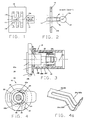
- a shift gate plate 10 is formed with a cut-out 10a through which a selector pin 12 extends from a control rod 14.
- Cut-out 10a is formed with a central opening 10b providing a neutral zone extending along an X-axis in the direction of the longitudinal axis 14a with a plurality of pairs of notches extending in a direction parallel to a Y-axis, i.e., perpendicular to the X-axis, to provide gear shift zones at a selected locations along the X-axis.
- the control rod is translatable along, as well as rotatable about, the longitudinal axis so that the selector pin can move along the X-axis between opposite ends of the cut-out and, upon rotational movement of the control rod about axis 14a, the selector pin rotates ( ⁇ -axis) and is movable into any one of the notches depending upon the position of the selector pin along the X-axis.
- selector pin 12 can move through neutral between one extreme position along the X-axis at gear states 1, 2, through a second position along the X-axis at gear states 3, 4 and an opposite extreme or third position along the X-axis at gear states 5, R.
- a position sensor apparatus 16 made in accordance with the a first embodiment of the invention is shown comprising a housing 18 having a generally cylindrical inner surface 18a for mounting a flexible substrate to be described below and may provide a bearing surface for a rotor assembly to be described and an end wall 18b for attachment, using conventional bolts or the like (not shown), to the shift tower 20 of an automotive manual transmission (not shown).
- a suitable seal such as a gasket (not shown) is preferably provided to create an environmental seal against a stationary base to protect internal components from fouling over the expected pressure differential and environmental conditions seen by the sensor, e.g., salt spray or other contaminants.
- Control rod 14 extends through a bore formed in boss 20a of the shift tower into a switch cavity 18c.
- a rotor 22 formed of electrically insulative material is fixedly mounted on control rod 14 and mounts thereon first and second electrically conductive wipers 24, 26.
- Wipers 24, 26 are formed of material have good spring characteristics as well as oxidation and corrosion resistance properties and are mounted on support platforms 22a, 22b respectively and are generally elongated strips having opposite cantilever mounted contact end surfaces biased toward the inside cylindrical surface 18a of the housing.
- the contact end surfaces are formed with a plurality of spring fingers 24a/26a as seen in Fig. 4a to provide redundant electrical engagement with any electrically conductive surface against which it is biased.
- Fig. 4a shows a bifurcated contact, it will be realized that any selected number of spring fingers can be employed, as desired.
- An electrical circuit is disposed on the inside cylindrical surface 18a and preferably comprises a flexible substrate 28 of suitable electrically insulative materials such as polyimide film, as seen in Figs. 5 and 6, on which first and second electrical resistive patterns are printed.
- the first resistive pattern comprises a plurality of elongated resistive elements 28a, 28b, 28c each extending in length in a first direction parallel to an X-axis, as denoted by arrow 14b, for a selected height h. Resistive elements 28a, 28b, 28c are serially connected by trace 28d between a voltage supply terminal Vs and a ground terminal GND.
- the resistive elements 28a, 28b, 28c together extend in an opposite or Y direction, as denoted by arrow 14c, a selected width w.
- a first contact pad 28e having a width generally equal to width w and a height generally equal to h is placed adjacent to the resistive elements and is connected to a first output terminal Vo(x) via trace 28d.
- the second resistive pattern comprises first, second and third elongated resistive elements 28f, 28g, 28h extending in length in a second different direction, preferably 90° to the first direction, parallel to a Y-axis, as indicated by arrow 14c and are serially connected between voltage supply terminal Vs and ground terminal GND by trace 28d.
- the resistive elements each extend in length a distance w and taken together in height across from one another a distance h.
- a second contact pad 28i is disposed intermediate to first contact pad 28e and the resistive elements 28f - 28h and has a size generally equal to w x h.
- Contact pad 28i is electrically connected to second output terminal vo( ⁇ )via conductive trace 28d. Wipers 24 and 26 are shown in Figs.
- Housing 18 may be formed with a connector portion (not shown) having four terminal pins (not shown) to provide electrical connection to the terminals described above on flexible substrate 28.
- contact pads 28e, 28i are of low electrical resistance, as by providing an underlying coating of highly electrically conductive material so that the total resistance at any given position is determined essentially by the respective resistance elements.
- traces 28d are of minimal electrical resistance.
- control rod 14 As control rod 14 is moved along the X-axis, one distal end 24a of contact wiper 24 wipes along contact pad 28e in continuous electrical engagement and the opposite end 24b of wiper 24 wipes along the length of resistive element 28b in continuous electrical engagement changing the resistive value by virtue of changing the effective length of resistive element 28b.
- the control rod 14 can be rotated about axis 14a, now serving as the ⁇ -axis, so that selector pin 12 moves into a notch of the cut-out 10a with the wiper end 24b concomitantly moving out of electrical engagement with resistive element 28b and into electrical engagement with a portion of resistive element 28a or 28c.
- the value of the effective resistance of the first resistive pattern being dependent upon the location of wiper end 24b.
- contact wiper 26 As control rod 14 moves along the X-axis, contact wiper 26 is also moving with contact wiper end 26a wiping along contact pad 28i in continuous electrical engagement therewith and contact wiper end 26b wiping across the widths of resistive elements 28f, 28g, 28h.
- contact wiper end 26b When the control rod is rotated with selector pin 12 entering into one of the notches of cut-out 10a, contact wiper end 26b then wipes in continuous electrical engagement with one of the resistive elements 28f-28h depending upon the location of the control rod along the X-axis 14a.
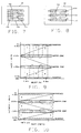
- the position sensor takes advantage of the travel restrictions imposed by the cut-out portion pattern 10a of shift gate plate 10 and essentially divides each axis of movement into three discrete output bands which correspond to desired transmission states or zones as illustrated in Figs. 7 and 8.
- Fig. 7 relates to translation along the X-axis and shows neutral zone 11b and gear engaging zones 11a, 11c respectively.
- Fig. 8 relates to rotation along the ⁇ -axis and shows zone 11d including gear states 1, 2, zone 11e including gear states 3, 4 and zone 11f including gear states 5, R respectively. Due to the common or overlapping areas of the output bands the position sensor has direct cross checking capability whereby the position relative to one axis can be determined from the output of the other axis.
- the specific output of the Vo(x) and Vo( ⁇ ) in volts for a sensor made in accordance with the first embodiment is shown in Figs. 9 and 10 respectively.
- the buffer zones are non-occurring output regions based on mechanical stack-up and circuit design.
- the reserved zones are output regions reserved for fault detection. It will be seen that each gear state, as well as neutral, has a different specific voltage output on each output terminal. Thus for gear state 3, for example, a voltage level approximately midway between supply voltage Vs and 2/3 supply voltage is obtained on the Vo(x) terminal and a voltage level of slightly under 2/3 voltage supply is obtained on the Vo( ⁇ ) terminal.
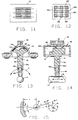
- This overlapping of discrete zones occurs in nine regions illustrated in Figs. 11 and 12.
- Fig. 11 shows the overlap relative to the shift pattern while Fig. 12 shows the overlap by the resistive elements.
- a position sensor 40 made in accordance with a second embodiment of the invention is shown in Figs. 13-16 in which the rotor 42 is mounted for translation and rotation on a shaft 44 fixedly attached to housing 46 extending across a switch chamber 46c defined by an inside cylindrical surface 46a of the housing.
- a connecting pin 48 extends radially from control rod 14 having a spherical free end portion 48a which is slidingly received in a socket 50 having a generally cylindrical inside surface 50a.
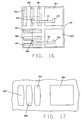
- resistive elements 28a', 28b' and 28c' of the first resistive pattern serially connected between supply voltage and ground and with contact pads 28e' connected to an X-axis output terminal.
- Resistive elements 28f', 28g' and 28h' are also serially connected between supply voltage and ground and with contact pad 28i' connected to a ⁇ -axis output terminal.
- the several terminals are connected to connector portion 52 in a conventional manner.
- Fig. 15 is a diagrammatic view illustrating the mechanical linkage of the ball and socket arrangement in which the radius from shaft 44 to the effective point of physical engagement between spherical surface 48a and cylindrical surface 50a, rl in Fig. 15, changes upon rotation of control rod 14 about axis 14a. This change introduces a non-linear effect in the shift ( ⁇ ) axis. This can be compensated by contouring the resistive elements 28a'', 28b'', 28c'' as shown in Fig. 17 with wider central portions than their respective end portions so that the resistance values relative to the various gear states will conform to the voltage output shown in Fig. 10.
Landscapes
- Engineering & Computer Science (AREA)
- General Engineering & Computer Science (AREA)
- Mechanical Engineering (AREA)
- Measurement Of Length, Angles, Or The Like Using Electric Or Magnetic Means (AREA)
- Transmission And Conversion Of Sensor Element Output (AREA)
- Arrangement Or Mounting Of Control Devices For Change-Speed Gearing (AREA)
- Control Of Transmission Device (AREA)
Applications Claiming Priority (2)
| Application Number | Priority Date | Filing Date | Title |
|---|---|---|---|
| US2577496P | 1996-09-24 | 1996-09-24 | |
| US25774P | 1996-09-24 |
Publications (2)
| Publication Number | Publication Date |
|---|---|
| EP0831253A2 true EP0831253A2 (fr) | 1998-03-25 |
| EP0831253A3 EP0831253A3 (fr) | 1999-12-29 |
Family
ID=21827995
Family Applications (1)
| Application Number | Title | Priority Date | Filing Date |
|---|---|---|---|
| EP97307487A Withdrawn EP0831253A3 (fr) | 1996-09-24 | 1997-09-24 | Dispositif de détection de position |
Country Status (2)
| Country | Link |
|---|---|
| EP (1) | EP0831253A3 (fr) |
| JP (1) | JPH10100708A (fr) |
Cited By (5)
| Publication number | Priority date | Publication date | Assignee | Title |
|---|---|---|---|---|
| FR2814524A1 (fr) * | 2000-09-22 | 2002-03-29 | Magneti Marelli France | Actionneur pour boite de vitesses mecanique de vehicules |
| FR2898395A1 (fr) * | 2006-03-10 | 2007-09-14 | Peugeot Citroen Automobiles Sa | Boite de vitesses equipee d'un capteur de position |
| WO2009000896A3 (fr) * | 2007-06-28 | 2009-03-05 | Kostal Leopold Gmbh & Co Kg | Dispositif de détection de positions de commutation |
| DE102013101503A1 (de) * | 2013-02-14 | 2014-08-14 | Knorr-Bremse Systeme für Nutzfahrzeuge GmbH | Fahrzeuggetriebe, Verfahren und Sensorvorrichtung zum Erfassen einer Schaltstellung eines Fahrzeuggetriebes |
| CN110259933A (zh) * | 2018-03-12 | 2019-09-20 | 舍弗勒技术股份两合公司 | 换挡系统和方法 |
Families Citing this family (2)
| Publication number | Priority date | Publication date | Assignee | Title |
|---|---|---|---|---|
| JP5040784B2 (ja) * | 2008-04-16 | 2012-10-03 | 日産自動車株式会社 | 変速操作装置 |
| JP5427057B2 (ja) * | 2010-02-09 | 2014-02-26 | パナソニック株式会社 | センサ装置と検出対象物との連結構造 |
Family Cites Families (9)
| Publication number | Priority date | Publication date | Assignee | Title |
|---|---|---|---|---|
| FR2308226A1 (fr) * | 1975-04-16 | 1976-11-12 | Tech Automatisme | Manipulateur electromecanique pour la commande electrique d'engins |
| GB2207508A (en) * | 1987-08-01 | 1989-02-01 | Crystalate Electronics | Potentiometer |
| DE3836145C2 (de) * | 1988-10-22 | 1997-06-05 | Fichtel & Sachs Ag | Anordnung zur Erfassung der Stellung eines Maschinenteils, insbesondere eines Gangschalthebels |
| DE4222878A1 (de) * | 1992-07-11 | 1994-01-13 | Fichtel & Sachs Ag | Anordnung zur Erfassung der Schaltstellung eines Kraftfahrzeuggetriebes |
| DE4233983A1 (de) * | 1992-10-09 | 1994-04-14 | Fichtel & Sachs Ag | Vorrichtung zur Erfassung der Gangstellung eines Schaltgetriebes |
| DE4311607A1 (de) * | 1993-04-08 | 1994-10-13 | Fichtel & Sachs Ag | Gangerkennungssensor für ein Schaltgetriebe eines Kraftfahrzeugs |
| EP0660084A1 (fr) * | 1993-12-23 | 1995-06-28 | General Motors Corporation | Capteur de rotation |
| DE4425210A1 (de) * | 1994-07-16 | 1996-01-18 | Zahnradfabrik Friedrichshafen | Lagesensor |
| JPH09509730A (ja) * | 1994-12-24 | 1997-09-30 | ルーク ゲトリーベ−ジステーメ ゲゼルシャフト ミット ベシュレンクテル ハフツング | 駆動ユニットと伝動装置との間で有効なトルク伝達系を制御するための装置及び方法 |
-
1997
- 1997-09-22 JP JP25718697A patent/JPH10100708A/ja active Pending
- 1997-09-24 EP EP97307487A patent/EP0831253A3/fr not_active Withdrawn
Non-Patent Citations (1)
| Title |
|---|
| None |
Cited By (8)
| Publication number | Priority date | Publication date | Assignee | Title |
|---|---|---|---|---|
| FR2814524A1 (fr) * | 2000-09-22 | 2002-03-29 | Magneti Marelli France | Actionneur pour boite de vitesses mecanique de vehicules |
| FR2898395A1 (fr) * | 2006-03-10 | 2007-09-14 | Peugeot Citroen Automobiles Sa | Boite de vitesses equipee d'un capteur de position |
| WO2007104880A3 (fr) * | 2006-03-10 | 2007-11-15 | Peugeot Citroen Automobiles Sa | Boite de vitesses equipee d'un capteur de position |
| WO2009000896A3 (fr) * | 2007-06-28 | 2009-03-05 | Kostal Leopold Gmbh & Co Kg | Dispositif de détection de positions de commutation |
| DE102013101503A1 (de) * | 2013-02-14 | 2014-08-14 | Knorr-Bremse Systeme für Nutzfahrzeuge GmbH | Fahrzeuggetriebe, Verfahren und Sensorvorrichtung zum Erfassen einer Schaltstellung eines Fahrzeuggetriebes |
| US10400894B2 (en) | 2013-02-14 | 2019-09-03 | Knorr-Bremse Systeme Fuer Nutzfahrzeuge Gmbh | Vehicle transmission, method, and sensor device for detecting a shifting position of a vehicle transmission |
| CN110259933A (zh) * | 2018-03-12 | 2019-09-20 | 舍弗勒技术股份两合公司 | 换挡系统和方法 |
| CN110259933B (zh) * | 2018-03-12 | 2022-08-05 | 舍弗勒技术股份两合公司 | 换挡系统和方法 |
Also Published As
| Publication number | Publication date |
|---|---|
| JPH10100708A (ja) | 1998-04-21 |
| EP0831253A3 (fr) | 1999-12-29 |
Similar Documents
| Publication | Publication Date | Title |
|---|---|---|
| US6212950B1 (en) | Glass interlaced fuel system low current rheostat | |
| US5856618A (en) | Position sensor apparatus | |
| DE69618725T2 (de) | analoge Steuerknüppelanzeigevorrichtung | |
| EP0771681B1 (fr) | Détecteur de rotation dans un véhicule | |
| JP4846986B2 (ja) | 密封型燃料レベルセンサ | |
| JP3469262B2 (ja) | 車両のトランスミッションのギア選択感応型センサ装置 | |
| EP0818645B1 (fr) | Capteur de position pour levier de commande de boíte de vitesses | |
| US6190264B1 (en) | Low-hysteresis coupling for angular-position and torque sensor | |
| WO2000039536A2 (fr) | Detecteur de niveau de carburant a carte a resistance ceramique miniaturisee | |
| US6882124B2 (en) | Sensor for adjustable vehicle systems | |
| JPH10100708A (ja) | 位置センサ装置 | |
| DE19649906C2 (de) | Sensor zur Erfassung von Drehwinkeln | |
| US6588288B1 (en) | Resistive element structure for a sender assembly of a gauge | |
| WO2002066294A1 (fr) | Module de colonne de direction | |
| US5675250A (en) | Angular position sensor having no physical electrical contact between a rotating portion and a stationary portion of the sensor | |
| EP0302670A2 (fr) | Potentiomètre | |
| US5099092A (en) | Position indicator assembly | |
| US5166628A (en) | Sliding contact electrical path or angle sensor | |
| JP3230102B2 (ja) | 摺動抵抗式リニア特性センサ | |
| US6979788B1 (en) | Electrical switch system responsive to gear selection of vehicular transmission | |
| JP5630768B2 (ja) | 回転型センサ | |
| KR950003075A (ko) | 서보모우터 원격제어스위치 | |
| EP0717266B1 (fr) | Capteur résistif variable | |
| US20060163046A1 (en) | Position sensor responsive to gear selection of vehicular transmission | |
| GB2269431A (en) | Arrangement for detecting the shift position of a vehicle transmission system comprises parallel resistance elements |
Legal Events
| Date | Code | Title | Description |
|---|---|---|---|
| PUAI | Public reference made under article 153(3) epc to a published international application that has entered the european phase |
Free format text: ORIGINAL CODE: 0009012 |
|
| AK | Designated contracting states |
Kind code of ref document: A2 Designated state(s): AT BE CH DE DK ES FI FR GB GR IE IT LI LU MC NL PT SE |
|
| AX | Request for extension of the european patent |
Free format text: AL;LT;LV;RO;SI |
|
| PUAL | Search report despatched |
Free format text: ORIGINAL CODE: 0009013 |
|
| AK | Designated contracting states |
Kind code of ref document: A3 Designated state(s): AT BE CH DE DK ES FI FR GB GR IE IT LI LU MC NL PT SE |
|
| AX | Request for extension of the european patent |
Free format text: AL;LT;LV;RO;SI |
|
| AKX | Designation fees paid | ||
| REG | Reference to a national code |
Ref country code: DE Ref legal event code: 8566 |
|
| STAA | Information on the status of an ep patent application or granted ep patent |
Free format text: STATUS: THE APPLICATION IS DEEMED TO BE WITHDRAWN |
|
| 18D | Application deemed to be withdrawn |
Effective date: 20000630 |