EP0831269A2 - Dispositif de basculement et sa méthode de support - Google Patents
Dispositif de basculement et sa méthode de support Download PDFInfo
- Publication number
- EP0831269A2 EP0831269A2 EP97115991A EP97115991A EP0831269A2 EP 0831269 A2 EP0831269 A2 EP 0831269A2 EP 97115991 A EP97115991 A EP 97115991A EP 97115991 A EP97115991 A EP 97115991A EP 0831269 A2 EP0831269 A2 EP 0831269A2
- Authority
- EP
- European Patent Office
- Prior art keywords
- tilting
- tilting device
- base body
- axis
- permanent magnet
- Prior art date
- Legal status (The legal status is an assumption and is not a legal conclusion. Google has not performed a legal analysis and makes no representation as to the accuracy of the status listed.)
- Granted
Links
Images
Classifications
-
- G—PHYSICS
- G02—OPTICS
- G02B—OPTICAL ELEMENTS, SYSTEMS OR APPARATUS
- G02B7/00—Mountings, adjusting means, or light-tight connections, for optical elements
- G02B7/18—Mountings, adjusting means, or light-tight connections, for optical elements for prisms; for mirrors
- G02B7/182—Mountings, adjusting means, or light-tight connections, for optical elements for prisms; for mirrors for mirrors
- G02B7/1821—Mountings, adjusting means, or light-tight connections, for optical elements for prisms; for mirrors for mirrors for rotating or oscillating mirrors
Definitions
- the invention relates to a method for storing a Tilting device according to the preamble of the first Claim and a tilting device, which according to this Process works.
- Such tilting devices are known from the prior art Technology well known. They serve one on them striking light beam defined by a certain angle distract. One differentiates in particular 1-axis and 2-axis tilting mirror.
- a tilting mirror arrangement is known from US Pat. No. 4,708,420, which is used for scanning.
- the scan mirror via flexible joints with piezoceramic drive elements connected, which is arranged parallel to the mirror surface are. So that the piezoceramic drive elements the mirror This arrangement must be able to tip over a large angle be great. This results from the slight bending of the Piezoceramic drive elements, which are proportional to the Length of these elements is. So this arrangement is not for that suitable for small mirrors around a large angular range tilt when the drive mechanism behind the tilt mirror the dimension of the mirror surface should be limited.
- a tilting mirror arrangement is known from US Pat. No. 4,383,763, in which the mirror is mounted on a tilt point and is moved over piezoelectric ceramics.
- the dimensions of the mirror will be very large if the tilting mirror should be tilted by at least 1 °.
- a tilting mirror holder is known from US Pat. No. 4,660,941, in which the tilting mirror movement by piezoelectric Elements is achieved and the piezoelectric elements act on the mirror via levers. This arrangement too is not suitable for a small mirror by at least 1 ° to tip.
- a piezoelectric beam reflector is known from US Pat. No. 5,170,277 known in which the mirror body directly on the piezoelectric element is attached. This has the disadvantage that the mirror does not have a defined pivot point when tilted owns.
- a piezoelectric beam reflector is known from US Pat. No. 4,691,212 known, which is used in a scanning arrangement becomes.
- the disadvantage of this arrangement is that a certain one Deflection angle cannot be kept rigid when the fulcrum should be firm.
- This object is achieved by a method according to the characterizing part of the first claim and a Tilting device according to the characteristic part of the third Claim resolved.
- the inventive method for storing a Tilting device enables tilting by at least one Axis and uses a tilt body, a base body and a bearing lying between these two bodies.
- the center of gravity of the tilting body lies in the fulcrum of the Storage. This has the great advantage that you only have energy for must bring up a change of position. The one that then arises The tilt position then remains without further energy expenditure.
- the tilting device resulting from the above requirement which tilting around at least one axis has one Tilt body, a base body and one between these two Bodies lying down.
- the tilting device stands out according to the invention in that a first part of the tilting body is arranged above the fulcrum that a second part of the tilting body below the pivot point is arranged and that the weight of the first part of the tilting body and the weight of the second part of the tilting body correspond to each other. But that is exactly the focus of the tilting body at the pivot point of the bearing.
- the base body with the tilting body is advantageous magnetically biased so that at an inclined position neither body by the influence of gravity separate from each other.
- a drive device in the tilting device is installed. This is particularly the case if you have movements controlled by the tilting device expected (e.g. for a light beam deflection, a movement a laser attached to the tilting device, etc.).
- the Drive device for an axis is more advantageous example from a coil on the base body and a magnet on Tilt body built. It is advantageous if the magnet is a permanent magnet.
- This position measuring system can advantageously from at least one Hall sensor and at least one permanent magnet be constructed. It is advantageous if the permanent magnet is attached to the tilting body.
- the tilting device according to the invention is suitable for everyone Applications in which it is at least uniaxial Movement over a relatively small, but exceeding 1 °, Tilt angle ( ⁇ 10 °, advantageously ⁇ 5 °) at relatively high tipping frequencies arrives.
- the applications include Scans, exposures, material removal, etc.
- the tilting device according to the invention build up large segment arrays, which consist of an areal Arrangement of many of the tilting device according to the invention exist because the drive mechanism is completely below the is arranged to tilt surface.
- both passive and Components e.g. mirror surfaces, etc.
- active components e.g. laser diodes
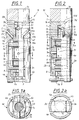
- the tilting device (10) shown in FIGS. 1 and 2 is exemplary as a tilting mirror with sensor system (9a) executed.
- the tilting device (10) shown consists in essentially from an upper tilting body (14), which itself relative to a lower base body (4) by one before constructively set amount. Between These two bodies (4, 14) have a bearing (3a, 3b, 3c, 3d).
- the bearing (3a, 3b, 3c, 3d) between the upper tilting body (14) and the lower base body (4) takes place via four bearing balls (3a, 3b, 3c, 3d), with a bearing ball (3a) fixed a receptacle (11) provided for this purpose on a cylindrical one Elevation (12) in the upper part of the base body (4) is connected and the three other bearing balls (3a, 3b, 3c) can move smoothly on it.
- the cylindrical Elevation (12) in the upper part of the base body (4) protrudes far into the larger opening (15) in the lower part (2) of the tilting body (14) into it.
- the tilting device (10) in any spatial Location (this is the spatial location or orientation of the Base body meant) can be used, the Center of gravity of the tilting body (14) and rigid with it connected parts in the fulcrum.
- the focus is on Pivot point, this has the decisive advantage that the once set spatial relation between tilting body (14) and base body (4) to each other without further energy expenditure remains. So you only need one Energy expenditure if you consider the spatial position between the tilting body (14) and base body (4) wants to change. But is this location of the tilting body (14) relative to the base body (4), see above no further energy is required around the tilting body (14) to keep in this position relative to the base body (4).
- this advantage of the storage according to the invention lowers the Energy consumption of the tilting device (10) is enormous and ensures to ensure that no heat build-up arises from waste heat. This is a big problem with a large number of those on the market Tilting mirror, especially if a small size is desired becomes.
- the movable tilting body (14) has downward, as well the fixed parts (4a and 4b) of the base body (4), the shape a slotted tube sleeve (see Figures 1 and 2).
- At the top Part (1) of the tilting body (14) has a mirror body (1) with mirrored surface (1a), which is fixed to the bearing body (2) attached under the mirror body (1) of the tilting body (14) is connected (e.g. glued).
- Two lateral elements extend on this bearing body (2) relatively thin apron body (2a, 2b) laterally downwards, which as a fastening body for one firmly attached to them attached first magnetic holder (7) made of titanium.
- this magnet holder (7) is a permanent magnet (7c) held that its magnetic poles (north and south poles) too the two coils (5, 6) point out.
- the first permanent magnet (7c) which part of the biaxial drive system is between the two attach fixed coils (5, 6) to the base body (4).
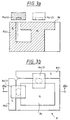
- a second permanent magnet (8) attached (see also Figures 3a and 3b), the Attachment by gluing the two bodies (2a, 2b; 8) with each other.
- the sleeve-shaped one makes it possible Shape of the tilting body (14) in its lower area, the second permanent magnet (8), which is part of the sensor system (see Figures 3a and 3b) on the movable tilting body (14) to be firmly attached (e.g. glued on).
- FIGS. 1 and 2 the magnetic north pole of the magnet below, and the apron body (2a, 2b) of the tilting body (14) are in this north-south extension direction arranged.
- Figure 1a shows the exact one Shape of the upper permanent magnet (7c) again clearly shown.
- the permanent magnet (7c) is supported by a magnet (7), which is a substantially cylindrical tubular Shape with different wall thicknesses with a circular middle opening for receiving the permanent magnet (7c) owns.
- the storage body (2) has two in its lower part inclined surfaces (2a, 2b) which are inclined obliquely upwards and each on the opposite sides of the storage body (2). In these inclined surfaces (2c, 2d) there is a recess in each one Permanent magnet (16a, 16b) is embedded. These two permanent magnets (16a, 16b) act with two obliquely arranged soft magnetic plates (17a, 17b) in the upper part of the Base body (4), which they are exactly opposite, such together that the tilting body (14) and the base body (4) are magnetically biased towards each other and the four Bearing balls (3a, 3b, 3c, 3d) are pressed together.
- the base body (4) is essentially a hollow cylinder body, which on both sides recesses (18a), (18b in the figure not shown) for receiving the apron body (2a, 2b) of the Tilting body (14) has. At the top of the base body (4) he has an upper cap (4c), from which in the Central axis, the cylindrical elevation (12) with its recording (11) protrudes for the bearing ball (3a).
- the inclined surfaces (17a, 17b) on the base body (4) exist made of a magnetic material (e.g. soft iron) and care together with the permanent magnets (16a, 16b) of the tilting body (14) for a magnetic bias between the base body (4) and Tilt body (14). Both magnetic poles of the permanent magnet (16a, 16b) lie opposite the inclined surfaces (17a, 17b), see above that by the magnetic circuit that can be achieved results in a greater holding force.
- a magnetic material e.g. soft iron
- a retaining web (5a) (preferably made of a magnetizable Material such as Soft iron) around which the turns a first coil (5) are wound.
- This first coil (5) lies in the tilting device (10) above that on the tilting body (14) attached first permanent magnet (7c) and serves together with this permanent magnet (7c) as a drive device for uniaxial relative adjustment between base body (4) and Tilt body (14).
- Their windings are perpendicular to the north-south axis of the magnet (7c).
- another retaining web (6a) (preferably from a magnetizable material such as Soft iron) around which the Windings of a second coil (6) wound transversely to the first are.
- This coil (6) serves together with the permanent magnet (7c) as a drive device for the second uniaxial relative adjustment between base body (4) and tilting body (14). Also their windings are perpendicular to the north-south axis of the magnet (7c) oriented, but are also perpendicular to the Windings of the first coil (5) oriented.
- both coils (5, 6) in terms of their winding directions) are oriented transversely to one another.
- the sensor system is used to determine the exact position of the Tilting device (10).
- several (at least one sensor (9a) for each Hall sensor (9a) attached which depending on the tilt angle of the tilting body (14) relative to the base body (4) give different voltage.
- the Hall sensors (9a) evaluate the Direction of the magnetic field of the permanent magnet (8).
- Form of the permanent magnet (8) of the sensor system is in particular off Figures 3a and 3b can be seen.
- the permanent magnet (8) is like this constructed a relatively large square north pole (8a) made of a suitable material that is so large that at the maximum permissible deflection of the tilting body (14) Hall sensor (9a (1), 9a (2)) of a tilt axis never to the middle of the magnetic north pole body (8a).
- the magnetic The south pole is so raised laterally that between the Surface of the magnetic north pole part (8a ') and magnetic south pole part (8b1 ', 8b2') each gives a gap.
- the two Hall sensors (9a (1), 9a (2)) are arranged.
- the Hall sensors (9a (1), 9a (2)) have thereby maximum sensitivity for tilting movements of the Tilting body (14) on which the permanent magnet (8) is attached is.
- the sensor system has a signal line to a computer system or to a control system for the coil current two coils (5, 6), so that if the position of the Tilting body (14) relative to a desired position Controls of the coils (5, 6) are readjusted as long as until the tilting body (10) has assumed the desired position.
- the two coils (5, 6) and the one with the Hall sensors (9a) equipped circuit board (9) are attached to the fixed parts (4a, 4b) of the base body (4) rigidly attached (e.g. glued in) before looking at the outer parts (4a, 4b) of the base body (4) rigidly attached (e.g. gluing during assembly).
- the preferred area of use for the tilting device is Use as a tilting mirror. These can be one or two axes be. Although currently on the market one and two-axis Tilt mirrors are available, so they have the disadvantage that they don't meet one or more of the above requirements able to fulfill.
- the tilting device according to the invention can in particular as small two-axis tilting mirror can be used, its size in the mirror plane is not bigger than the mirror itself, the mirror surface (1a) typically being a circle of 3-12 mm Diameter is. In doing so, two are perpendicular to each other stationary axes a tilting movement of at least ⁇ 1.5 ° to 3 ° reached, the angular resolution within approximately half possible tilt angle range 2048 individual steps reached ( ⁇ 0.8 ° at tilt angle ⁇ 1.5 °).
- a permanently installed sensor system (9) available, the actual position of the tilting body (14) relative to the base body (4) determined.
- the tilting device (10) is as Module built to a segmented from several modules to be able to put together larger mirrors. Besides, that is Tilting device (14) suitable for inexpensive mass production.
Landscapes
- Physics & Mathematics (AREA)
- General Physics & Mathematics (AREA)
- Optics & Photonics (AREA)
- Mechanical Optical Scanning Systems (AREA)
- Measurement Of Length, Angles, Or The Like Using Electric Or Magnetic Means (AREA)
- Testing Of Balance (AREA)
- Vibration Prevention Devices (AREA)
- Mounting And Adjusting Of Optical Elements (AREA)
- Mechanical Light Control Or Optical Switches (AREA)
Applications Claiming Priority (4)
| Application Number | Priority Date | Filing Date | Title |
|---|---|---|---|
| DE19638213 | 1996-09-19 | ||
| DE19638213 | 1996-09-19 | ||
| DE19701485 | 1997-01-17 | ||
| DE19701485A DE19701485A1 (de) | 1996-09-19 | 1997-01-17 | Verfahren zur Lagerung einer Kippvorrichtung und Kippvorrichtung |
Publications (3)
| Publication Number | Publication Date |
|---|---|
| EP0831269A2 true EP0831269A2 (fr) | 1998-03-25 |
| EP0831269A3 EP0831269A3 (fr) | 1998-07-08 |
| EP0831269B1 EP0831269B1 (fr) | 2003-09-10 |
Family
ID=26029536
Family Applications (1)
| Application Number | Title | Priority Date | Filing Date |
|---|---|---|---|
| EP97115991A Expired - Lifetime EP0831269B1 (fr) | 1996-09-19 | 1997-09-15 | Dispositif de basculement |
Country Status (3)
| Country | Link |
|---|---|
| US (1) | US5803609A (fr) |
| EP (1) | EP0831269B1 (fr) |
| JP (1) | JPH10104535A (fr) |
Cited By (1)
| Publication number | Priority date | Publication date | Assignee | Title |
|---|---|---|---|---|
| CN104781715A (zh) * | 2012-11-29 | 2015-07-15 | 卡尔蔡司Smt有限责任公司 | 用于致动光学系统中的至少一个光学元件的装置 |
Families Citing this family (2)
| Publication number | Priority date | Publication date | Assignee | Title |
|---|---|---|---|---|
| US7273289B2 (en) | 2005-05-19 | 2007-09-25 | Euv Llc | Vacuum compatible, high-speed, 2-D mirror tilt stage |
| US7709782B2 (en) * | 2006-01-17 | 2010-05-04 | Newport Corporation | Optical assembly with adjustable optical element and independently tunable position sensors |
Citations (6)
| Publication number | Priority date | Publication date | Assignee | Title |
|---|---|---|---|---|
| US4383763A (en) | 1979-09-12 | 1983-05-17 | Litton Systems, Inc. | Controllable mirrors |
| US4660941A (en) | 1984-02-24 | 1987-04-28 | Shuzo Hattori | Light deflection apparatus |
| US4691212A (en) | 1985-11-14 | 1987-09-01 | Xerox Corporation | Piezoelectric optical beam deflector |
| US4708420A (en) | 1984-05-24 | 1987-11-24 | The Commonwealth Of Australia | Focal plane scanning device |
| US5170277A (en) | 1988-05-11 | 1992-12-08 | Symbol Technologies, Inc. | Piezoelectric beam deflector |
| DE19519161A1 (de) | 1994-05-25 | 1995-11-30 | Marconi Gec Ltd | Piezoelektrische Abtastvorrichtung |
Family Cites Families (6)
| Publication number | Priority date | Publication date | Assignee | Title |
|---|---|---|---|---|
| US3245707A (en) * | 1963-11-06 | 1966-04-12 | Taylor Instrument Co | Pivotal coupling for instrument linkage |
| US3946166A (en) * | 1974-04-01 | 1976-03-23 | Zenith Radio Corporation | Tracking arrangement |
| NL174608C (nl) * | 1975-10-20 | 1984-07-02 | Philips Nv | Werkwijze voor de vervaardiging van een zwenkspiegelinrichting en een zwenkspiegelinrichting vervaardigd volgens deze werkwijze. |
| JPS53108403A (en) * | 1977-03-04 | 1978-09-21 | Sony Corp | Mirror supporting device for video disc |
| US4854687A (en) * | 1988-02-04 | 1989-08-08 | United Technologies Corporation | Beam steering mirror construction |
| DE19504568A1 (de) * | 1995-02-11 | 1996-08-14 | Zeiss Carl Fa | Kippspiegelanordnung |
-
1997
- 1997-09-15 EP EP97115991A patent/EP0831269B1/fr not_active Expired - Lifetime
- 1997-09-19 JP JP9254787A patent/JPH10104535A/ja active Pending
- 1997-09-19 US US08/934,291 patent/US5803609A/en not_active Expired - Fee Related
Patent Citations (6)
| Publication number | Priority date | Publication date | Assignee | Title |
|---|---|---|---|---|
| US4383763A (en) | 1979-09-12 | 1983-05-17 | Litton Systems, Inc. | Controllable mirrors |
| US4660941A (en) | 1984-02-24 | 1987-04-28 | Shuzo Hattori | Light deflection apparatus |
| US4708420A (en) | 1984-05-24 | 1987-11-24 | The Commonwealth Of Australia | Focal plane scanning device |
| US4691212A (en) | 1985-11-14 | 1987-09-01 | Xerox Corporation | Piezoelectric optical beam deflector |
| US5170277A (en) | 1988-05-11 | 1992-12-08 | Symbol Technologies, Inc. | Piezoelectric beam deflector |
| DE19519161A1 (de) | 1994-05-25 | 1995-11-30 | Marconi Gec Ltd | Piezoelektrische Abtastvorrichtung |
Cited By (3)
| Publication number | Priority date | Publication date | Assignee | Title |
|---|---|---|---|---|
| CN104781715A (zh) * | 2012-11-29 | 2015-07-15 | 卡尔蔡司Smt有限责任公司 | 用于致动光学系统中的至少一个光学元件的装置 |
| US9665011B2 (en) | 2012-11-29 | 2017-05-30 | Carl Zeiss Smt Gmbh | Arrangement for actuating at least one optical element in an optical system |
| US10303065B2 (en) | 2012-11-29 | 2019-05-28 | Carl Zeiss Smt Gmbh | Arrangement for actuating at least one optical element in an optical system |
Also Published As
| Publication number | Publication date |
|---|---|
| EP0831269A3 (fr) | 1998-07-08 |
| JPH10104535A (ja) | 1998-04-24 |
| EP0831269B1 (fr) | 2003-09-10 |
| US5803609A (en) | 1998-09-08 |
Similar Documents
| Publication | Publication Date | Title |
|---|---|---|
| DE4023311C2 (fr) | ||
| EP2411761B2 (fr) | Appareil laser multi-raies à autonivellement | |
| EP2411762B1 (fr) | Appareil laser à 360°, à plusieurs lignes et à nivellement automatique | |
| EP0349911B1 (fr) | Micromanipulateur | |
| EP0726479B1 (fr) | Arrangement d'un miroir pivotant | |
| CH709292A2 (de) | Positioniervorrichtung für einen Bildstabilisator. | |
| DE3542154A1 (de) | Lichtumlenkvorrichtung | |
| DE3804242C2 (fr) | ||
| WO2010145803A1 (fr) | Support cinématique | |
| DE102009001882A1 (de) | Selbstnivellierendes Linien-Lasergerät | |
| EP1939586A2 (fr) | Dispositif de projection laser | |
| EP0376107A2 (fr) | Téléscope avec stabilisation d'image | |
| DE3843776A1 (de) | Fernrohr mit bildfeldstabilisierung | |
| EP0831351B1 (fr) | Dispositif de basculement | |
| EP0831269B1 (fr) | Dispositif de basculement | |
| DE202008008821U1 (de) | Laservorrichtung | |
| DE19701485A1 (de) | Verfahren zur Lagerung einer Kippvorrichtung und Kippvorrichtung | |
| DE102013114822B3 (de) | Zweiachsige Kippvorrichtung | |
| DE102018113847B3 (de) | Halterung zur Befestigung eines Sensors | |
| WO1988001434A1 (fr) | Porte-echantillon deplaçable pour un microscope a rayonnement corpusculaire | |
| DE19823725B4 (de) | Optische Ablenkvorrichtung | |
| DE10244867A1 (de) | Einrichtung zum Positionieren eines Körpers | |
| DE4224600A1 (de) | Elektrostatische Positionierungseinrichtung | |
| DE10216114A1 (de) | Vorrichtung zur deformationsarmen Lagerung eines nicht rotationssymmetrischen optischen Elementes | |
| EP1650590B1 (fr) | Dispositif d'ajustement destiné au positionnement très précis d'un objet |
Legal Events
| Date | Code | Title | Description |
|---|---|---|---|
| PUAI | Public reference made under article 153(3) epc to a published international application that has entered the european phase |
Free format text: ORIGINAL CODE: 0009012 |
|
| AK | Designated contracting states |
Kind code of ref document: A2 Designated state(s): CH DE FR GB IT LI |
|
| PUAL | Search report despatched |
Free format text: ORIGINAL CODE: 0009013 |
|
| AK | Designated contracting states |
Kind code of ref document: A3 Designated state(s): AT BE CH DE DK ES FI FR GB GR IE IT LI LU MC NL PT SE |
|
| 17P | Request for examination filed |
Effective date: 19990107 |
|
| AKX | Designation fees paid |
Free format text: AT BE CH DE DK LI |
|
| RBV | Designated contracting states (corrected) |
Designated state(s): AT BE CH DE DK LI |
|
| RBV | Designated contracting states (corrected) |
Designated state(s): CH DE FR GB IT LI |
|
| 17Q | First examination report despatched |
Effective date: 20000301 |
|
| RTI1 | Title (correction) |
Free format text: TILTING DEVICE |
|
| RTI1 | Title (correction) |
Free format text: TILTING DEVICE |
|
| RTI1 | Title (correction) |
Free format text: TILTING DEVICE |
|
| GRAH | Despatch of communication of intention to grant a patent |
Free format text: ORIGINAL CODE: EPIDOS IGRA |
|
| GRAH | Despatch of communication of intention to grant a patent |
Free format text: ORIGINAL CODE: EPIDOS IGRA |
|
| GRAA | (expected) grant |
Free format text: ORIGINAL CODE: 0009210 |
|
| AK | Designated contracting states |
Kind code of ref document: B1 Designated state(s): CH DE FR GB IT LI |
|
| PG25 | Lapsed in a contracting state [announced via postgrant information from national office to epo] |
Ref country code: IT Free format text: LAPSE BECAUSE OF FAILURE TO SUBMIT A TRANSLATION OF THE DESCRIPTION OR TO PAY THE FEE WITHIN THE PRESCRIBED TIME-LIMIT;WARNING: LAPSES OF ITALIAN PATENTS WITH EFFECTIVE DATE BEFORE 2007 MAY HAVE OCCURRED AT ANY TIME BEFORE 2007. THE CORRECT EFFECTIVE DATE MAY BE DIFFERENT FROM THE ONE RECORDED. Effective date: 20030910 Ref country code: GB Free format text: LAPSE BECAUSE OF FAILURE TO SUBMIT A TRANSLATION OF THE DESCRIPTION OR TO PAY THE FEE WITHIN THE PRESCRIBED TIME-LIMIT Effective date: 20030910 Ref country code: FR Free format text: LAPSE BECAUSE OF FAILURE TO SUBMIT A TRANSLATION OF THE DESCRIPTION OR TO PAY THE FEE WITHIN THE PRESCRIBED TIME-LIMIT Effective date: 20030910 |
|
| RAP1 | Party data changed (applicant data changed or rights of an application transferred) |
Owner name: CARL-ZEISS-STIFTUNG, TRADING AS CARL ZEISS Owner name: CARL ZEISS |
|
| REG | Reference to a national code |
Ref country code: GB Ref legal event code: FG4D Free format text: NOT ENGLISH |
|
| REG | Reference to a national code |
Ref country code: CH Ref legal event code: EP |
|
| PG25 | Lapsed in a contracting state [announced via postgrant information from national office to epo] |
Ref country code: LI Free format text: LAPSE BECAUSE OF NON-PAYMENT OF DUE FEES Effective date: 20030930 Ref country code: CH Free format text: LAPSE BECAUSE OF NON-PAYMENT OF DUE FEES Effective date: 20030930 |
|
| REF | Corresponds to: |
Ref document number: 59710718 Country of ref document: DE Date of ref document: 20031016 Kind code of ref document: P |
|
| GBV | Gb: ep patent (uk) treated as always having been void in accordance with gb section 77(7)/1977 [no translation filed] |
Effective date: 20030910 |
|
| PG25 | Lapsed in a contracting state [announced via postgrant information from national office to epo] |
Ref country code: DE Free format text: LAPSE BECAUSE OF NON-PAYMENT OF DUE FEES Effective date: 20040401 |
|
| REG | Reference to a national code |
Ref country code: CH Ref legal event code: PL |
|
| PLBE | No opposition filed within time limit |
Free format text: ORIGINAL CODE: 0009261 |
|
| STAA | Information on the status of an ep patent application or granted ep patent |
Free format text: STATUS: NO OPPOSITION FILED WITHIN TIME LIMIT |
|
| RAP2 | Party data changed (patent owner data changed or rights of a patent transferred) |
Owner name: CARL-ZEISS-STIFTUNG TRADING AS CARL ZEISS Owner name: CARL ZEISS |
|
| 26N | No opposition filed |
Effective date: 20040614 |
|
| EN | Fr: translation not filed |