EP0831275B1 - Ringbrennkammer für Gasturbinen - Google Patents
Ringbrennkammer für Gasturbinen Download PDFInfo
- Publication number
- EP0831275B1 EP0831275B1 EP97115032A EP97115032A EP0831275B1 EP 0831275 B1 EP0831275 B1 EP 0831275B1 EP 97115032 A EP97115032 A EP 97115032A EP 97115032 A EP97115032 A EP 97115032A EP 0831275 B1 EP0831275 B1 EP 0831275B1
- Authority
- EP
- European Patent Office
- Prior art keywords
- diffuser
- gas turbine
- air flow
- type gas
- annular type
- Prior art date
- Legal status (The legal status is an assumption and is not a legal conclusion. Google has not performed a legal analysis and makes no representation as to the accuracy of the status listed.)
- Expired - Lifetime
Links
- 230000001105 regulatory effect Effects 0.000 claims description 45
- 238000011144 upstream manufacturing Methods 0.000 claims description 2
- 239000007789 gas Substances 0.000 description 17
- 230000033228 biological regulation Effects 0.000 description 6
- 238000002485 combustion reaction Methods 0.000 description 6
- 238000010276 construction Methods 0.000 description 5
- 238000010790 dilution Methods 0.000 description 4
- 239000012895 dilution Substances 0.000 description 4
- 239000000446 fuel Substances 0.000 description 3
- 239000000567 combustion gas Substances 0.000 description 2
- 238000001816 cooling Methods 0.000 description 2
- 230000007423 decrease Effects 0.000 description 2
- 230000000694 effects Effects 0.000 description 2
- 230000003252 repetitive effect Effects 0.000 description 2
- 239000012141 concentrate Substances 0.000 description 1
- 230000003247 decreasing effect Effects 0.000 description 1
- 230000001419 dependent effect Effects 0.000 description 1
- 238000004519 manufacturing process Methods 0.000 description 1
- 238000005096 rolling process Methods 0.000 description 1
Images


Classifications
-
- F—MECHANICAL ENGINEERING; LIGHTING; HEATING; WEAPONS; BLASTING
- F23—COMBUSTION APPARATUS; COMBUSTION PROCESSES
- F23R—GENERATING COMBUSTION PRODUCTS OF HIGH PRESSURE OR HIGH VELOCITY, e.g. GAS-TURBINE COMBUSTION CHAMBERS
- F23R3/00—Continuous combustion chambers using liquid or gaseous fuel
- F23R3/02—Continuous combustion chambers using liquid or gaseous fuel characterised by the air-flow or gas-flow configuration
- F23R3/26—Controlling the air flow
-
- F—MECHANICAL ENGINEERING; LIGHTING; HEATING; WEAPONS; BLASTING
- F05—INDEXING SCHEMES RELATING TO ENGINES OR PUMPS IN VARIOUS SUBCLASSES OF CLASSES F01-F04
- F05B—INDEXING SCHEME RELATING TO WIND, SPRING, WEIGHT, INERTIA OR LIKE MOTORS, TO MACHINES OR ENGINES FOR LIQUIDS COVERED BY SUBCLASSES F03B, F03D AND F03G
- F05B2250/00—Geometry
- F05B2250/40—Movement of component
- F05B2250/41—Movement of component with one degree of freedom
Definitions
- the present invention relates to an annular type combustor applied to a gas turbine.
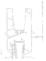
- FIG. 4 is a schematic cross sectional view of a combustor, taken on a vertical plane including a turbine central axis, which shows an upper half portion only of the turbine central axis. That is, an annular type combustor forms a combustor which is concentric with the turbine central axis and annular (like a doughnut shape) surrounding the turbine central axis, together with a lower half portion (not shown) of the turbine central axis.
- numeral 1 designates a pre-diffuser
- numeral 2 designates a diffuser case
- numeral 3 designates a fuel injector
- numeral 4 designates a swirler
- numeral 5 designates a liner
- numeral 6 designates a dilution hole
- numeral 7 designates a cooling hole
- numeral 8 designates a rotating ring.
- air passes through the pre-diffuser 1 and enters a combustion region surrounded by the liner 5 via the swirler 4, the dilution hole 6, the cooling hole 7, etc.
- level of NO x included in an emission gas is influenced by a ratio of fuel to air passing through the swirler 4 (hereinafter referred to as "fuel-air ratio”), and generally as the fuel-air ratio is lowered, the NO x level becomes lower.
- fuel-air ratio a ratio of fuel to air passing through the swirler 4
- a rotary type flow regulating mechanism employing the rotating ring 8 is provided at the swirler 4, by which opening cross sectional area of the swirler is changed and the fuel-air ratio is regulated.
- the rotating ring 8 has an approximately same structure as the swirler 4 and is constructed by swirling blades, each having a certain thickness. Air flow is regulated by the rotating ring 8 which is rotated so that a relative phase to the swirler 4 is changed.
- the opening cross sectional area becomes maximum and as the relative phase is caused to deviate from this state, as shown in Fig. 6, the opening cross sectional area can be reduced corresponding to the amount of such deviation. According to change of the opening cross sectional area, flow rate of air passing through the swirler 4 is increased or decreased with result that the fuel-air ratio can be regulated.
- the rotating ring which is a movable portion for regulating the fuel-air ratio is disposed at a position which is easily influenced by flames thus there is a problem that the rotating ring is heated to a high temperature so as to lose its durability and reliability. Also, in such arrangement, there is a problem that a complicated mechanism of the movable portion is needed as a countermeasure for thermal expansion etc.
- Another prior art combustor for a gas turbine described in US-A-3 905 192 has a movable bell mouth piece positioned at a forward end of a fuel atomizer or nozzle.
- the bell mouth piece is axially slidable and retractable to open or close an air duct section downstream of the nozzle.
- the air flow distribution regulating device is positioned directly in a fuel-air mixing region of the combustor and therefore in a zone which is exposed to considerably high temperatures.
- the present invention provides an annular type gas turbine combustor as defined in claim 1.
- Preferred embodiments of the combustor are defined in the dependent claims.
- the air flow distribution regulating device when air supplied downstream from the pre-diffuser passes through the air flow distribution regulating device at the terminal end of the pre-diffuser, the air flow distribution regulating device is slid in the axial direction and distribution of the air flowing downstream is regulated in a desired direction so as to obtain an optimized combustion.
- said air flow distribution regulating device is disposed at the terminal end of the pre-diffuser, as mentioned above, which is apart from flames so as not to be influenced by the flames, thus there is no fear of lowering of durability due to high temperature flames.
- the present invention also provides an annular type gas turbine combustor in which the air flow distribution regulating device is in the form of a slide duct surrounding the pre-diffuser and said slide duct is divided into a plurality of parts which are divided in the circumferential direction and the divided parts are slidable in the axial direction independent of each other. Thereby each of the divided parts can be slid to various sliding patterns so as to effect appropriate regulations of distribution of the air flowing downstream from the pre-diffuser to meet operation conditions.
- the present invention also provides an annular type gas turbine combustor in which a roller is disposed between the pre-diffuser and the air flow distribution regulating device, thereby relative movement of the pre-diffuser and the air flow distribution regulating device is done smoothly by the effect of rolling of the roll and the distribution of air flow-can be regulated securely and easily.
- the present invention also provides an annular type gas turbine combustor in which each of the pre-diffuser and the air flow distribution regulating device has a circular cross sectional shape and is disposed concentrically with each other, thereby the supplied air flows in a concentrically distributed form and the air flow distribution in the radial direction becomes uniform, so that a regular combustion can be attained.
- the present invention also provides an annular type gas turbine combustor in which each of the pre-diffuser and the air flow distribution regulating device has a polygonal cross sectional shape and is disposed concentrically with each other, thereby even if the pre-diffuser is formed in a polygonal cross sectional shape, the air flow distribution regulating device can well conform to that shape and the distribution of air flow can be regulated securely.
- the present invention also provides an annular type gas turbine combustor in which the air flow distribution regulating device has its end face formed in a wave shape, thereby there occurs a differential position in the axial direction between a tip position and a bottom position of the wave shape and making use of said differential position, flow-out position of the supplied air is caused to change in the axial direction, so that the distribution of air flow in the circumferential direction can be regulated finely.
- the present invention also provides an annular type gas turbine combustor in which the air flow distribution regulating device is constructed so as to be rotatable around a gas turbine center axis, thereby the air flow distribution regulating device is rotated in addition to movement in the axial direction and a fine and appropriate regulation of the air flow distribution can be effected further.
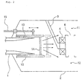
- Fig. 1 is a schematic cross sectional view of a combustor of a first embodiment according to the present invention.
- Fig. 2 is an explanatory view of regulation status of the combustor of Fig. 1.
- Fig. 3 is a schematic cross sectional view of a combustor of a second embodiment according to the present invention.
- Fig. 4 is a schematic cross sectional view of a prior art combustor.
- Fig. 5 is a cross sectional view taken on line A-A of Fig. 4.
- Fig. 6 is a cross sectional view taken on line B-B of Fig. 5.
- FIG. 1 A first embodiment according to the present invention is described with reference to Figs. 1 and 2. It is to be noted that same portions as those in the above-mentioned prior art are denoted with same numerals in the figures and characteristic features of the present embodiment are described with repetitive description being omitted.
- the air flow distribution regulating device of the present embodiment employs a slide duct 10, which slide duct 10 is disposed at an end portion of a pre-diffuser 1 concentrically with the pre-diffuser 1 so as to surrounded an outer circumferential surface of the pre-diffuser 1.
- the slide duct 10 is constructed integratedly by two divided objects, one being an outer side portion shown in an upper part of Fig. 1 and the other being an inner side portion shown in a lower part of Fig. 1, with a strut 14 being interposed between said two divided objects.
- a roller 13 is disposed, and an actuator 15 which connects to outside is connected to a portion of the slide duct 10, so that the slide duct 10, when pushed or pulled by the actuator 15, is movable in the axial direction of the pre-diffuser 1.
- the slide duct 10 as shown here is of two divided objects, upper and lower in the figure or outer and inner around the gas turbine axis, but it is not limited to the two divided objects but can be of a single unit or of objects divided into a plurality of more than 2 in a circumferential direction according to convenience of manufacture.
- the integrated slide duct may summarily be of a cross sectional shape conformable to, and slidable in the axial direction on, the shape of the pre-diffuser, whether circular or polygonal.
- the outer slide duct and the inner slide duct are-moved independent of each other and distribution of air flow led to an outer shroud passage 11 and an inner shroud passage 12 is regulated.
- a ratio of flow rate of an outer dilution air and an inner dilution air can be changed and a temperature distribution of combustion gas at an outlet portion 9 of the combustor can be optimized.
- a downstream side end face of the slide duct 10 is flat both in the first and second embodiments, an arbitrary shape of end face, such as uneven end face of wave-shape, for example, can be employed and also it is possible that the air flow distribution can be regulated in a circumferential direction.
- the air flow distribution regulating device which is slidable in the axial direction is disposed at the terminal end of the pre-diffuser, distribution of air flow led to the downstream swirler can be regulated, and by this flow regulation, fuel-air ratio can also be regulated with result that the fuel-air ratio is lowered at the time of high load operation and NO x can be reduced. Also, at the time of low load operation, the fuel-air ratio is enhanced so that a stable combustion can be attained.
- the air flow distribution regulating device is disposed in a close vicinity of the pre-diffuser, thus it is not influenced by flames, its movable portions can be made simpler and an apparatus of high durability and reliability can be provided.
- the air flow distribution regulating device is circumferentially divided into a plurality of parts and each of the divided parts is made movable independent of each other, thereby a fine regulation of air flow corresponding to combustion state becomes possible and a combustion gas temperature distribution at the outlet portion of the combustor can be optimized.
- partial variations such as a construction that the roller is disposed between the pre-diffuser and the air flow distribution regulating device, a construction that the pre-diffuser and the air flow distribution regulating device, each, has a circular or polygonal cross sectional shape and is disposed concentrically with each other, a construction that the air flow distribution regulating device has its end face formed in a wave-shape and a construction that the air flow distribution regulating device is constructed rotatively around the gas turbine axis, are appropriately selected and added, thereby distribution of supplied air flow can be finely regulated in the axial direction and circumferential direction.
Landscapes
- Engineering & Computer Science (AREA)
- Chemical & Material Sciences (AREA)
- Combustion & Propulsion (AREA)
- Mechanical Engineering (AREA)
- General Engineering & Computer Science (AREA)
- Air Supply (AREA)
- Pre-Mixing And Non-Premixing Gas Burner (AREA)
Claims (10)
- Ringförmiger Gasturbinen-Combustor mit:einem ringförmigen Combustorgehäuse (2) mit einem Brennstoff-Luft-Mischbereich,einem Vorzerstäuber (1), der am Einlassende des Combustorgehäuses (2) vorgesehen ist, um dem Brennstoff-Luft-Mischbereich des Combustors stromab des Vorzerstäubers (1) Luft zuzuführen, wobei der Vorzerstäuber (1) ein Abschlussende aufweist,einer Luftstromverteilungs-Regelungsvorrichtung (10), die am Abschlussende des Vorzerstäubers (1) und stromauf des Brennstoff-Luft-Mischbereichs angeordnet und in einer Axialrichtung des Vorzerstäubers (1) verschiebbar ist, um den Luftstrom stromab des Vorzerstäubers (1) zu regeln.
- Ringförmiger Gasturbinen-Combustor nach Anspruch 1, wobei die Luftstromverteilungs-Regelungsvorrichtung (10) die Form eines die Außenumfangsfläche des Vorzerstäubers (1) umgebenden Schiebekanals aufweist und einen radial äußeren Kanalteil und einen radial inneren Kanalteil umfasst.
- Ringförmiger Gasturbinen-Combustor nach Anspruch 2, wobei der radial äußere Kanalteil und der radial innere Kanalteil integral miteinander verbunden sind und mit einem Aktuator bzw. Stellglied (15) zum Ausführen der Schiebebewegung des Kanals in der Axialrichtung des Vorzerstäubers (1) verbunden sind.
- Ringförmiger Gasturbinen-Combustor nach Anspruch 2, wobei der radial äußere Kanalteil und der radial innere Kanalteil jeweils mit einem Aktuator (15a,15b) zum unabhängigen Ausführen der Schiebebewegung der Kanalteile in der Axialrichtung des Vorzerstäubers (1) verbunden sind.
- Ringförmiger Gasturbinen-Combustor nach einem der Ansprüche 2 bis 4, wobei der Schiebekanal in mehrere Teile in der Umfangsrichtung unterteilt ist und die unterteilten Teile in der Axialrichtung unabhängig voneinander verschiebbar bzw. gleitfähig sind.
- Ringförmiger Gasturbinen-Combustor nach einem der Ansprüche 1 bis 5, wobei eine Rolle bzw. Walze (13) zwischen dem Vorzerstäuber (1) und der Luftstromverteilungs-Regelungsvorrichtung (10) angeordnet ist.
- Ringförmiger Gasturbinen-Combustor nach einem der Ansprüche 1 bis 6, wobei die Luftstromverteilungs-Regelungsvorrichtung (10) eine Querschnittsform aufweist, die sich der Form des Vorzerstäubers (1) anpasst ist.
- Ringförmiger Gasturbinen-Combustor nach Anspruch 7, wobei der Vorzerstäuber (1) und die Luftstromverteilungs-Regelungsvorrichtung (10) jeweils eine kreisförmige oder eine polygonale Querschnittsform aufweisen und konzentrisch zueinander angeordnet sind.
- Ringförmiger Gasturbinen-Combustor nach einem der Ansprüche 1 bis 8, wobei die Luftstromverteilungs-Regelungsvorrichtung (10) ihre stromabwärtige axiale Endfläche in einer Wellenform ausgebildet hat.
- Ringförmiger Gasturbinen-Combustor nach Anspruch 6, wobei die Luftstromverteilungs-Regelungsvorrichtung (10) so aufgebaut ist, dass sie um eine Gasturbinen-Mittelachse drehbar ist.
Applications Claiming Priority (3)
| Application Number | Priority Date | Filing Date | Title |
|---|---|---|---|
| JP25144396A JP3706443B2 (ja) | 1996-09-24 | 1996-09-24 | アニュラ型ガスタービン燃焼器 |
| JP25144396 | 1996-09-24 | ||
| JP251443/96 | 1996-09-24 |
Publications (3)
| Publication Number | Publication Date |
|---|---|
| EP0831275A2 EP0831275A2 (de) | 1998-03-25 |
| EP0831275A3 EP0831275A3 (de) | 2000-07-19 |
| EP0831275B1 true EP0831275B1 (de) | 2003-08-13 |
Family
ID=17222915
Family Applications (1)
| Application Number | Title | Priority Date | Filing Date |
|---|---|---|---|
| EP97115032A Expired - Lifetime EP0831275B1 (de) | 1996-09-24 | 1997-08-29 | Ringbrennkammer für Gasturbinen |
Country Status (4)
| Country | Link |
|---|---|
| US (1) | US5918459A (de) |
| EP (1) | EP0831275B1 (de) |
| JP (1) | JP3706443B2 (de) |
| DE (1) | DE69724063T2 (de) |
Cited By (1)
| Publication number | Priority date | Publication date | Assignee | Title |
|---|---|---|---|---|
| US6925809B2 (en) | 1999-02-26 | 2005-08-09 | R. Jan Mowill | Gas turbine engine fuel/air premixers with variable geometry exit and method for controlling exit velocities |
Families Citing this family (9)
| Publication number | Priority date | Publication date | Assignee | Title |
|---|---|---|---|---|
| US6272842B1 (en) * | 1999-02-16 | 2001-08-14 | General Electric Company | Combustor tuning |
| EP1036988A3 (de) * | 1999-02-26 | 2001-05-16 | R. Jan Mowill | Kraftstoff/Luft-Vormischeinrichtung mit veränderlicher Geometrie und Methode, die Ausströmgeschwindigkeit zu regeln |
| GB2351343A (en) | 1999-06-22 | 2000-12-27 | Alstom Gas Turbines Ltd | Telescopically-moveable combustion chamber |
| US6253538B1 (en) * | 1999-09-27 | 2001-07-03 | Pratt & Whitney Canada Corp. | Variable premix-lean burn combustor |
| EP1319896A3 (de) * | 2001-12-14 | 2004-05-12 | R. Jan Mowill | Kraftstoff/Luft-Vormischeinrichtung mit veränderlicher Geometrie und Methode, die Ausströmgeschwindigkeit zu regeln |
| JP6028578B2 (ja) * | 2013-01-15 | 2016-11-16 | 株式会社Ihi | 燃焼器 |
| US20140216038A1 (en) * | 2013-02-06 | 2014-08-07 | General Electric Company | Variable Volume Combustor with Cantilevered Support Structure |
| US11578869B2 (en) * | 2021-05-20 | 2023-02-14 | General Electric Company | Active boundary layer control in diffuser |
| CN114576651B (zh) * | 2022-01-13 | 2023-01-06 | 南京航空航天大学 | 一种扩压器空气流量分配智能调节系统及其工作方法 |
Family Cites Families (8)
| Publication number | Priority date | Publication date | Assignee | Title |
|---|---|---|---|---|
| US2655787A (en) * | 1949-11-21 | 1953-10-20 | United Aircraft Corp | Gas turbine combustion chamber with variable area primary air inlet |
| US4044549A (en) * | 1972-12-11 | 1977-08-30 | Zwick Eugene B | Low emission combustion process and apparatus |
| US3905192A (en) * | 1974-08-29 | 1975-09-16 | United Aircraft Corp | Combustor having staged premixing tubes |
| DE2659351A1 (de) * | 1976-12-29 | 1978-07-06 | Daimler Benz Ag | Brennkammer fuer gasturbinen |
| US4532762A (en) * | 1982-07-22 | 1985-08-06 | The Garrett Corporation | Gas turbine engine variable geometry combustor apparatus |
| EP0312620B1 (de) * | 1987-10-19 | 1991-06-12 | Hitachi, Ltd. | Einrichtung zur Regulierung des Verbrennungsluftdurchsatzes in Gasturbinenbrennkammern |
| JP2954401B2 (ja) * | 1991-08-23 | 1999-09-27 | 株式会社日立製作所 | ガスタービン設備およびその運転方法 |
| JPH0579629A (ja) * | 1991-09-19 | 1993-03-30 | Hitachi Ltd | 燃焼器およびその運転方法 |
-
1996
- 1996-09-24 JP JP25144396A patent/JP3706443B2/ja not_active Expired - Lifetime
-
1997
- 1997-08-26 US US08/917,466 patent/US5918459A/en not_active Expired - Lifetime
- 1997-08-29 EP EP97115032A patent/EP0831275B1/de not_active Expired - Lifetime
- 1997-08-29 DE DE69724063T patent/DE69724063T2/de not_active Expired - Fee Related
Cited By (1)
| Publication number | Priority date | Publication date | Assignee | Title |
|---|---|---|---|---|
| US6925809B2 (en) | 1999-02-26 | 2005-08-09 | R. Jan Mowill | Gas turbine engine fuel/air premixers with variable geometry exit and method for controlling exit velocities |
Also Published As
| Publication number | Publication date |
|---|---|
| JP3706443B2 (ja) | 2005-10-12 |
| US5918459A (en) | 1999-07-06 |
| DE69724063T2 (de) | 2004-06-17 |
| JPH1096516A (ja) | 1998-04-14 |
| EP0831275A2 (de) | 1998-03-25 |
| DE69724063D1 (de) | 2003-09-18 |
| EP0831275A3 (de) | 2000-07-19 |
Similar Documents
| Publication | Publication Date | Title |
|---|---|---|
| US5303542A (en) | Fuel supply control method for a gas turbine engine | |
| US5289685A (en) | Fuel supply system for a gas turbine engine | |
| CA2381018C (en) | Variable premix-lean burn combustor | |
| EP1064501B1 (de) | Scheibe zur vermischung von brennstoff und luft für brennkammern mit mageren und geringem nox-ausstoss | |
| CA2245203C (en) | Gas turbine combustor | |
| US5660045A (en) | Gas turbine combustor and gas turbine | |
| JP2839777B2 (ja) | ガスタービン燃焼器用燃料噴射ノズル | |
| US6971242B2 (en) | Burner for a gas turbine engine | |
| EP0476927B1 (de) | Brennstoffeinspritzdüsenhalter | |
| EP1413830B1 (de) | Druckluftinjektor für Kraftstoff mit verbessertem Luftverteiler und Pilot | |
| US6122916A (en) | Pilot cones for dry low-NOx combustors | |
| EP0673490B1 (de) | Brennstoff-einspritzdüse | |
| US5899074A (en) | Gas turbine combustor and operation method thereof for a diffussion burner and surrounding premixing burners separated by a partition | |
| EP0800041B1 (de) | Gasturbinenbrennkamer | |
| EP0358437B1 (de) | Kraftstoff-Luftvormischvorrichtung für eine Gasturbine | |
| US6895755B2 (en) | Nozzle with flow equalizer | |
| US5121608A (en) | Gas turbine engine fuel burner | |
| JPH05149149A (ja) | ガスタービン燃焼器 | |
| EP1319896A2 (de) | Kraftstoff/Luft-Vormischeinrichtung mit veränderlicher Geometrie und Methode, die Ausströmgeschwindigkeit zu regeln | |
| EP1207344B1 (de) | Brennkammer | |
| US5918459A (en) | Annular type gas turbine combustor | |
| US20090217669A1 (en) | Fuel nozzles | |
| EP1445538A1 (de) | Brennstoffeinspritzdüse | |
| JPH0882419A (ja) | ガスタービン用燃焼器 | |
| CN118347016A (zh) | 一种采用旋流-非旋流组合进气头部结构的同心分级高温升燃烧室及方法 |
Legal Events
| Date | Code | Title | Description |
|---|---|---|---|
| PUAI | Public reference made under article 153(3) epc to a published international application that has entered the european phase |
Free format text: ORIGINAL CODE: 0009012 |
|
| 17P | Request for examination filed |
Effective date: 19970926 |
|
| AK | Designated contracting states |
Kind code of ref document: A2 Designated state(s): DE FR GB |
|
| AX | Request for extension of the european patent |
Free format text: AL;LT;LV;RO;SI |
|
| PUAL | Search report despatched |
Free format text: ORIGINAL CODE: 0009013 |
|
| AK | Designated contracting states |
Kind code of ref document: A3 Designated state(s): AT BE CH DE DK ES FI FR GB GR IE IT LI LU MC NL PT SE |
|
| AX | Request for extension of the european patent |
Free format text: AL;LT;LV;RO;SI |
|
| AKX | Designation fees paid |
Free format text: DE FR GB |
|
| 17Q | First examination report despatched |
Effective date: 20011228 |
|
| GRAH | Despatch of communication of intention to grant a patent |
Free format text: ORIGINAL CODE: EPIDOS IGRA |
|
| GRAH | Despatch of communication of intention to grant a patent |
Free format text: ORIGINAL CODE: EPIDOS IGRA |
|
| GRAA | (expected) grant |
Free format text: ORIGINAL CODE: 0009210 |
|
| AK | Designated contracting states |
Designated state(s): DE FR GB |
|
| REG | Reference to a national code |
Ref country code: GB Ref legal event code: FG4D |
|
| REF | Corresponds to: |
Ref document number: 69724063 Country of ref document: DE Date of ref document: 20030918 Kind code of ref document: P |
|
| ET | Fr: translation filed | ||
| PLBE | No opposition filed within time limit |
Free format text: ORIGINAL CODE: 0009261 |
|
| STAA | Information on the status of an ep patent application or granted ep patent |
Free format text: STATUS: NO OPPOSITION FILED WITHIN TIME LIMIT |
|
| 26N | No opposition filed |
Effective date: 20040514 |
|
| PGFP | Annual fee paid to national office [announced via postgrant information from national office to epo] |
Ref country code: FR Payment date: 20050809 Year of fee payment: 9 |
|
| PGFP | Annual fee paid to national office [announced via postgrant information from national office to epo] |
Ref country code: DE Payment date: 20050825 Year of fee payment: 9 |
|
| PG25 | Lapsed in a contracting state [announced via postgrant information from national office to epo] |
Ref country code: DE Free format text: LAPSE BECAUSE OF NON-PAYMENT OF DUE FEES Effective date: 20070301 |
|
| REG | Reference to a national code |
Ref country code: FR Ref legal event code: ST Effective date: 20070430 |
|
| PG25 | Lapsed in a contracting state [announced via postgrant information from national office to epo] |
Ref country code: FR Free format text: LAPSE BECAUSE OF NON-PAYMENT OF DUE FEES Effective date: 20060831 |
|
| PGFP | Annual fee paid to national office [announced via postgrant information from national office to epo] |
Ref country code: GB Payment date: 20160824 Year of fee payment: 20 |
|
| REG | Reference to a national code |
Ref country code: GB Ref legal event code: PE20 Expiry date: 20170828 |
|
| PG25 | Lapsed in a contracting state [announced via postgrant information from national office to epo] |
Ref country code: GB Free format text: LAPSE BECAUSE OF EXPIRATION OF PROTECTION Effective date: 20170828 |