EP0831282A2 - Plinthe chauffante pour installer des systèmes de chauffage our d'air conditionné et des cables pour électricité et/ou antenne - Google Patents
Plinthe chauffante pour installer des systèmes de chauffage our d'air conditionné et des cables pour électricité et/ou antenne Download PDFInfo
- Publication number
- EP0831282A2 EP0831282A2 EP97113737A EP97113737A EP0831282A2 EP 0831282 A2 EP0831282 A2 EP 0831282A2 EP 97113737 A EP97113737 A EP 97113737A EP 97113737 A EP97113737 A EP 97113737A EP 0831282 A2 EP0831282 A2 EP 0831282A2
- Authority
- EP
- European Patent Office
- Prior art keywords
- cover profile
- convector
- heating
- profile
- strip according
- Prior art date
- Legal status (The legal status is an assumption and is not a legal conclusion. Google has not performed a legal analysis and makes no representation as to the accuracy of the status listed.)
- Granted
Links
- 238000004378 air conditioning Methods 0.000 title claims description 5
- 238000009434 installation Methods 0.000 claims abstract description 8
- 238000010438 heat treatment Methods 0.000 claims description 14
- 238000010408 sweeping Methods 0.000 claims description 7
- 239000004922 lacquer Substances 0.000 claims description 3
- 125000006850 spacer group Chemical group 0.000 claims description 2
- 238000005422 blasting Methods 0.000 claims 1
- 230000005611 electricity Effects 0.000 claims 1
- 238000010079 rubber tapping Methods 0.000 abstract 1
- 239000000725 suspension Substances 0.000 abstract 1
- 230000000087 stabilizing effect Effects 0.000 description 3
- 241000446313 Lamella Species 0.000 description 2
- 244000007853 Sarothamnus scoparius Species 0.000 description 1
- 238000005452 bending Methods 0.000 description 1
- 230000005489 elastic deformation Effects 0.000 description 1
- 238000010616 electrical installation Methods 0.000 description 1
- 239000008236 heating water Substances 0.000 description 1
- 238000003780 insertion Methods 0.000 description 1
- 230000037431 insertion Effects 0.000 description 1
- 239000002184 metal Substances 0.000 description 1
Images

Classifications
-
- F—MECHANICAL ENGINEERING; LIGHTING; HEATING; WEAPONS; BLASTING
- F24—HEATING; RANGES; VENTILATING
- F24H—FLUID HEATERS, e.g. WATER OR AIR HEATERS, HAVING HEAT-GENERATING MEANS, e.g. HEAT PUMPS, IN GENERAL
- F24H3/00—Air heaters
- F24H3/002—Air heaters using electric energy supply
-
- F—MECHANICAL ENGINEERING; LIGHTING; HEATING; WEAPONS; BLASTING
- F24—HEATING; RANGES; VENTILATING
- F24D—DOMESTIC- OR SPACE-HEATING SYSTEMS, e.g. CENTRAL HEATING SYSTEMS; DOMESTIC HOT-WATER SUPPLY SYSTEMS; ELEMENTS OR COMPONENTS THEREFOR
- F24D19/00—Details
- F24D19/02—Arrangement of mountings or supports for radiators
- F24D19/04—Arrangement of mountings or supports for radiators in skirtings
-
- F—MECHANICAL ENGINEERING; LIGHTING; HEATING; WEAPONS; BLASTING
- F24—HEATING; RANGES; VENTILATING
- F24H—FLUID HEATERS, e.g. WATER OR AIR HEATERS, HAVING HEAT-GENERATING MEANS, e.g. HEAT PUMPS, IN GENERAL
- F24H9/00—Details
- F24H9/02—Casings; Cover lids; Ornamental panels
-
- H—ELECTRICITY
- H02—GENERATION; CONVERSION OR DISTRIBUTION OF ELECTRIC POWER
- H02G—INSTALLATION OF ELECTRIC CABLES OR LINES, OR OF COMBINED OPTICAL AND ELECTRIC CABLES OR LINES
- H02G3/00—Installations of electric cables or lines or protective tubing therefor in or on buildings, equivalent structures or vehicles
- H02G3/02—Details
- H02G3/04—Protective tubing or conduits, e.g. cable ladders or cable troughs
- H02G3/0425—Plinths
-
- E—FIXED CONSTRUCTIONS
- E04—BUILDING
- E04F—FINISHING WORK ON BUILDINGS, e.g. STAIRS, FLOORS
- E04F19/00—Other details of constructional parts for finishing work on buildings
- E04F19/02—Borders; Finishing strips, e.g. beadings; Light coves
- E04F19/04—Borders; Finishing strips, e.g. beadings; Light coves for use between floor or ceiling and wall, e.g. skirtings
- E04F2019/044—Borders; Finishing strips, e.g. beadings; Light coves for use between floor or ceiling and wall, e.g. skirtings with conduits
-
- E—FIXED CONSTRUCTIONS
- E04—BUILDING
- E04F—FINISHING WORK ON BUILDINGS, e.g. STAIRS, FLOORS
- E04F19/00—Other details of constructional parts for finishing work on buildings
- E04F19/02—Borders; Finishing strips, e.g. beadings; Light coves
- E04F19/04—Borders; Finishing strips, e.g. beadings; Light coves for use between floor or ceiling and wall, e.g. skirtings
- E04F2019/044—Borders; Finishing strips, e.g. beadings; Light coves for use between floor or ceiling and wall, e.g. skirtings with conduits
- E04F2019/0445—Ventilating plinths
Definitions
- the invention has for its object to provide a heating bar of the type described above, the individual components are such that none of the noises caused by differences in thermal expansion are generated, which is suitable for installing at least one electrical line which offers the possibility to everyone To provide electrical sockets and / or antenna sockets at any point along the length of the sweeping strip.
- the heating sweeping strip according to the invention has a suitable shape to act as an outlet duct of an air conditioning duct provided in the floor area.
- the invention proposes a holder which has clips for fastening the convector tubes by pushing them in, seats for snapping on electrical installation ducts and vertical branch ducts for electrical sockets, antenna sockets and / or telephone connection sockets, and there are also guide elements for the air throughput and slats provided with elastic compensation of the deformations caused by the thermal expansion.
- the mounting elements are shaped in such a way that simple and quick assembly and disassembly of the parts is possible without the use of specific tools.
- the holder for the broom according to the invention has at least one seat for clipping on a pipe or an electrical resistor for the convector to be installed.
- the shape of the jaws forming this clip-on seat is, according to the invention, such that, during the insertion of the convector, they cause a lateral elastic bending of the lamellae, which resiliently contact the said jaws laterally.
- the convector slats point be it against the surface on which the dustpan is mounted, be it against the cover profile, extensions on which protrude at an angle of a little more than 90 ° and so, be it on the mounting wall or mutually against the inner surface of the cover profile lay under elastic deformation in order to secure the heat transfer, even during the thermal expansion of the slats.
- the invention provides for covering the surfaces with a heat-resistant lacquer or the like, or for applying a heat-resistant film.
- the invention proposes to provide notches on the lamellae in which connecting and stabilizing strips made of metal or plastic are used with pressure and which in turn are placed in corresponding seats on the protrusions of the Bracket to be clipped.
- receptacles are provided for the attachment of at least one installation channel for an electrical line, for a telephone line and / or an antenna line.
- a vertical installation duct can be attached to the outside of the cover profile, which allows branching to one or more electrical, telephone and / or antenna sockets located above the bend profile
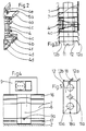
- the bracket 4 which has a flange in the upper region for the purpose of using a discharge profile 6, is fastened to the vertical wall 1 by means of screws 5.
- a hanging flange 4a for the engagement groove 7a of the cover profile 7 protrudes in the upper area, while a fastening flange 4b is provided in the lower area for fastening the cover profile 7 by means of screw 9a.
- Two clips 4c with elastic jaws protrude between said flanges 4a and 4b for the purpose of being received by pressing in the convector tubes 10 together with fins 12.
- the holder 4 has fastening elements 4d for the attachment of at least one installation channel 13 for mains power, telephone and / or antennas.
- a vertical branch duct 8 together with at least one socket at any point along the longitudinal extent of the cover profile 7; the socket is attached above the discharge profile 6.
- the vertical channel 8 has spacers 14a on its inside, on which the holding elements 14b for the cables 14, which are possibly provided with a reflective cover, are pressed or snapped on.
- the cover profile 7 is shaped and has corresponding dimensions such that a free opening for the throughput of the cold air 17 is provided in the vicinity of the floor 2 and a free opening for the throughput of the warm air 3b is provided in the upper region.
- the dimensions of the fins 12 and the bend of the extensions 12a and 12b are such that in the assembly position the fins are elastically deformed and exert a slight pressure against the contact surfaces, which favors the heat transfer and possible noises caused by the thermal expansion, especially during the temperature rise and Temperature drop that would occur can be prevented.
- the contact surfaces between the lamella extensions 12a, 12b and the cover profile 7, or the wall 1, can be covered by heat-resistant lacquer or laminates in order to additionally prevent the occurrence of noise caused by thermal expansion.
- the jaws of the clips 4c according to the invention have a conical shape that tapers towards the free ends so that they can slide like wedges between the lamellae 12 of the convector in order to spread them apart elastically and thus to facilitate assembly and to prevent heat expansion noises.
- the invention provides for connecting and stabilizing strips 18 to be pressed into notches 18a on the lamellae.
- the strips 18 in turn snap into corresponding receptacles on the hanging flanges 4a, 4b.
- the heating baffle can serve as an outlet channel for the air 3 a, 3 b of an air conditioning system distributed in the floor 3 near the bend.
Landscapes
- Engineering & Computer Science (AREA)
- General Engineering & Computer Science (AREA)
- Chemical & Material Sciences (AREA)
- Thermal Sciences (AREA)
- Combustion & Propulsion (AREA)
- Mechanical Engineering (AREA)
- Physics & Mathematics (AREA)
- Civil Engineering (AREA)
- Architecture (AREA)
- Structural Engineering (AREA)
- Central Heating Systems (AREA)
- Domestic Hot-Water Supply Systems And Details Of Heating Systems (AREA)
- Details Of Aerials (AREA)
- Duct Arrangements (AREA)
- Casings For Electric Apparatus (AREA)
Applications Claiming Priority (2)
| Application Number | Priority Date | Filing Date | Title |
|---|---|---|---|
| ITBZ960041 | 1996-09-23 | ||
| IT96BZ000041A IT1288266B1 (it) | 1996-09-23 | 1996-09-23 | Battiscopa termico per l'installazione di sistemi di riscaldamneto, di condizionamento, di linee elettriche e/o antenne. |
Publications (3)
| Publication Number | Publication Date |
|---|---|
| EP0831282A2 true EP0831282A2 (fr) | 1998-03-25 |
| EP0831282A3 EP0831282A3 (fr) | 1999-05-06 |
| EP0831282B1 EP0831282B1 (fr) | 2002-04-17 |
Family
ID=11346765
Family Applications (1)
| Application Number | Title | Priority Date | Filing Date |
|---|---|---|---|
| EP97113737A Expired - Lifetime EP0831282B1 (fr) | 1996-09-23 | 1997-08-08 | Plinthe chauffante pour installer des systèmes de chauffage our d'air conditionné et des cables pour électricité et/ou antenne |
Country Status (4)
| Country | Link |
|---|---|
| EP (1) | EP0831282B1 (fr) |
| AT (1) | ATE216480T1 (fr) |
| DE (1) | DE59707024D1 (fr) |
| IT (1) | IT1288266B1 (fr) |
Cited By (5)
| Publication number | Priority date | Publication date | Assignee | Title |
|---|---|---|---|---|
| FR2805336A1 (fr) * | 2000-02-23 | 2001-08-24 | Atlantic Industrie Sas | Dispositif de support de corps de chauffe |
| AT409036B (de) * | 1998-03-05 | 2002-05-27 | Vaillant Gmbh | Anschlusseinrichtung |
| CN101832013A (zh) * | 2010-02-12 | 2010-09-15 | 王振水 | 电热供暖踢脚线 |
| EP2796798A1 (fr) | 2013-04-26 | 2014-10-29 | ECO-MATIC (Société à responsabilité limitée) | Plinthe chauffante hydraulique et/ou électrique |
| DE102015005619B4 (de) | 2015-04-30 | 2020-06-10 | Günther Geyer | Installationskanal |
Families Citing this family (1)
| Publication number | Priority date | Publication date | Assignee | Title |
|---|---|---|---|---|
| RU205600U1 (ru) * | 2020-07-29 | 2021-07-22 | Кирилл Владимирович Бунчук | Регулируемый крепеж водяного плинтуса |
Family Cites Families (4)
| Publication number | Priority date | Publication date | Assignee | Title |
|---|---|---|---|---|
| BE529599A (fr) * | ||||
| DE1454341A1 (de) * | 1963-07-12 | 1969-03-27 | Rau Herbert | Fussleistenheizung |
| FR2222627B1 (fr) * | 1973-03-21 | 1978-12-29 | Profil Sa Ind Financ Le | |
| CA2116333A1 (fr) * | 1991-08-23 | 1993-03-04 | Manfred Fennesz | Plinthe chauffante a couvercle en bois |
-
1996
- 1996-09-23 IT IT96BZ000041A patent/IT1288266B1/it active IP Right Grant
-
1997
- 1997-08-08 AT AT97113737T patent/ATE216480T1/de active
- 1997-08-08 DE DE59707024T patent/DE59707024D1/de not_active Expired - Lifetime
- 1997-08-08 EP EP97113737A patent/EP0831282B1/fr not_active Expired - Lifetime
Non-Patent Citations (1)
| Title |
|---|
| None |
Cited By (6)
| Publication number | Priority date | Publication date | Assignee | Title |
|---|---|---|---|---|
| AT409036B (de) * | 1998-03-05 | 2002-05-27 | Vaillant Gmbh | Anschlusseinrichtung |
| FR2805336A1 (fr) * | 2000-02-23 | 2001-08-24 | Atlantic Industrie Sas | Dispositif de support de corps de chauffe |
| CN101832013A (zh) * | 2010-02-12 | 2010-09-15 | 王振水 | 电热供暖踢脚线 |
| CN101832013B (zh) * | 2010-02-12 | 2013-04-17 | 王振水 | 电热供暖踢脚线 |
| EP2796798A1 (fr) | 2013-04-26 | 2014-10-29 | ECO-MATIC (Société à responsabilité limitée) | Plinthe chauffante hydraulique et/ou électrique |
| DE102015005619B4 (de) | 2015-04-30 | 2020-06-10 | Günther Geyer | Installationskanal |
Also Published As
| Publication number | Publication date |
|---|---|
| IT1288266B1 (it) | 1998-09-11 |
| DE59707024D1 (de) | 2002-05-23 |
| ATE216480T1 (de) | 2002-05-15 |
| EP0831282B1 (fr) | 2002-04-17 |
| ITBZ960041A1 (it) | 1998-03-23 |
| EP0831282A3 (fr) | 1999-05-06 |
Similar Documents
| Publication | Publication Date | Title |
|---|---|---|
| DE69117294T2 (de) | Regelbare platte- und befestigungseinrichtung | |
| EP0831282B1 (fr) | Plinthe chauffante pour installer des systèmes de chauffage our d'air conditionné et des cables pour électricité et/ou antenne | |
| EP0176478A1 (fr) | Plinthe, en tant qu'élément d'installation servant à accueillir un noyau de chauffage | |
| DE102017105557B4 (de) | Einrichtung zum Temperieren von Räumen | |
| AT506308B1 (de) | Befestigungsvorrichtung und verfahren zum anschluss hydraulischer leitungen | |
| EP2012390A2 (fr) | Pince de mise à la terre destinée à l'équilibrage du potentiel de canaux de câblage | |
| DE3315786A1 (de) | Anschlussdose fuer insbesondere eine wasserleitungsanlage | |
| DE1759289C2 (de) | Wand- oder Deckenbekleidung | |
| DE102020208201A1 (de) | Heiz- oder Kühlkörper, insbesondere mehrreihiger Flachheizkörper oder Heizwand in vertikaler oder horizontaler Anordnung, mit mindestens einer Lüfterbaugruppe | |
| DE102010016177B4 (de) | Heizeinrichtung für den Einbau in einen Schaltschrank | |
| DE19803114A1 (de) | Wärmetauscherdecke mit Wärmeleitelementen | |
| WO2007000444A2 (fr) | Dispositif de chauffage et/ou de refroidissement d'une piece | |
| DE102014110844A1 (de) | Vorrichtung zum Beheizen von Räumen | |
| EP1271063B1 (fr) | Echangeur de chaleur, notamment plinthe chauffante | |
| DE102015102237B3 (de) | Deckenklimatisierungseinrichtung | |
| DE19801165C1 (de) | Heizungsanlage mit mindestens einem Heizelement zur Raumheizung | |
| DE20006211U1 (de) | Decken- und Fußleistenheizkörper | |
| DE29910425U1 (de) | Wand- oder Deckenvorbau mit integrierter Raumheizungs- bzw. Kühlungsanlage und Halterung hierfür | |
| EP1526018B1 (fr) | Dispositif de chauffage avec chauffage électrique supplémentaire integré | |
| DE102022113591A1 (de) | Leistenheizung | |
| DE9320445U1 (de) | Vorrichtung zur Befestigung einer Abdeckplatte an einem Plattenheizkörper | |
| DE29801344U1 (de) | Wärmetauscherdecke mit Wärmeleitelementen | |
| DE19609217A1 (de) | Rohrleitungssystem | |
| EP1413833B1 (fr) | Profil de guidage et convecteur | |
| AT402344B (de) | Anschlussvorrichtung für einen heizkörper |
Legal Events
| Date | Code | Title | Description |
|---|---|---|---|
| PUAI | Public reference made under article 153(3) epc to a published international application that has entered the european phase |
Free format text: ORIGINAL CODE: 0009012 |
|
| AK | Designated contracting states |
Kind code of ref document: A2 Designated state(s): AT DE FR GB |
|
| AX | Request for extension of the european patent |
Free format text: AL;LT;LV;RO;SI |
|
| 17P | Request for examination filed |
Effective date: 19980930 |
|
| PUAL | Search report despatched |
Free format text: ORIGINAL CODE: 0009013 |
|
| AK | Designated contracting states |
Kind code of ref document: A3 Designated state(s): AT BE CH DE DK ES FI FR GB GR IE IT LI LU MC NL PT SE |
|
| AX | Request for extension of the european patent |
Free format text: AL;LT;LV;RO;SI |
|
| AKX | Designation fees paid |
Free format text: AT DE FR GB |
|
| RTI1 | Title (correction) |
Free format text: BASEBOARD HEATER FOR INSTALLING HEATING- OR AIR CONDITIONING SYSTEMS AND ELECTRICAL- AND/OR ANTENNA WIRES |
|
| GRAG | Despatch of communication of intention to grant |
Free format text: ORIGINAL CODE: EPIDOS AGRA |
|
| 17Q | First examination report despatched |
Effective date: 20010209 |
|
| APAB | Appeal dossier modified |
Free format text: ORIGINAL CODE: EPIDOS NOAPE |
|
| APBJ | Interlocutory revision of appeal recorded |
Free format text: ORIGINAL CODE: EPIDOS IRAPE |
|
| GRAG | Despatch of communication of intention to grant |
Free format text: ORIGINAL CODE: EPIDOS AGRA |
|
| GRAH | Despatch of communication of intention to grant a patent |
Free format text: ORIGINAL CODE: EPIDOS IGRA |
|
| GRAH | Despatch of communication of intention to grant a patent |
Free format text: ORIGINAL CODE: EPIDOS IGRA |
|
| REG | Reference to a national code |
Ref country code: GB Ref legal event code: IF02 |
|
| GRAA | (expected) grant |
Free format text: ORIGINAL CODE: 0009210 |
|
| AK | Designated contracting states |
Kind code of ref document: B1 Designated state(s): AT DE FR GB |
|
| PG25 | Lapsed in a contracting state [announced via postgrant information from national office to epo] |
Ref country code: GB Free format text: LAPSE BECAUSE OF FAILURE TO SUBMIT A TRANSLATION OF THE DESCRIPTION OR TO PAY THE FEE WITHIN THE PRESCRIBED TIME-LIMIT Effective date: 20020417 Ref country code: FR Free format text: LAPSE BECAUSE OF FAILURE TO SUBMIT A TRANSLATION OF THE DESCRIPTION OR TO PAY THE FEE WITHIN THE PRESCRIBED TIME-LIMIT Effective date: 20020417 |
|
| REF | Corresponds to: |
Ref document number: 216480 Country of ref document: AT Date of ref document: 20020515 Kind code of ref document: T |
|
| REF | Corresponds to: |
Ref document number: 59707024 Country of ref document: DE Date of ref document: 20020523 |
|
| GBV | Gb: ep patent (uk) treated as always having been void in accordance with gb section 77(7)/1977 [no translation filed] |
Effective date: 20020417 |
|
| EN | Fr: translation not filed | ||
| PLBE | No opposition filed within time limit |
Free format text: ORIGINAL CODE: 0009261 |
|
| STAA | Information on the status of an ep patent application or granted ep patent |
Free format text: STATUS: NO OPPOSITION FILED WITHIN TIME LIMIT |
|
| 26N | No opposition filed |
Effective date: 20030120 |
|
| PGFP | Annual fee paid to national office [announced via postgrant information from national office to epo] |
Ref country code: AT Payment date: 20100830 Year of fee payment: 14 |
|
| PGFP | Annual fee paid to national office [announced via postgrant information from national office to epo] |
Ref country code: DE Payment date: 20100930 Year of fee payment: 14 |
|
| REG | Reference to a national code |
Ref country code: DE Ref legal event code: R119 Ref document number: 59707024 Country of ref document: DE Effective date: 20120301 |
|
| REG | Reference to a national code |
Ref country code: AT Ref legal event code: MM01 Ref document number: 216480 Country of ref document: AT Kind code of ref document: T Effective date: 20110808 |
|
| PG25 | Lapsed in a contracting state [announced via postgrant information from national office to epo] |
Ref country code: AT Free format text: LAPSE BECAUSE OF NON-PAYMENT OF DUE FEES Effective date: 20110808 |
|
| PG25 | Lapsed in a contracting state [announced via postgrant information from national office to epo] |
Ref country code: DE Free format text: LAPSE BECAUSE OF NON-PAYMENT OF DUE FEES Effective date: 20120301 |