EP0831310A2 - Procédé et dispositif pour déterminer l'atténuation additionnel météorologique du son - Google Patents
Procédé et dispositif pour déterminer l'atténuation additionnel météorologique du son Download PDFInfo
- Publication number
- EP0831310A2 EP0831310A2 EP97116062A EP97116062A EP0831310A2 EP 0831310 A2 EP0831310 A2 EP 0831310A2 EP 97116062 A EP97116062 A EP 97116062A EP 97116062 A EP97116062 A EP 97116062A EP 0831310 A2 EP0831310 A2 EP 0831310A2
- Authority
- EP
- European Patent Office
- Prior art keywords
- sound
- point
- determined
- called
- reflection
- Prior art date
- Legal status (The legal status is an assumption and is not a legal conclusion. Google has not performed a legal analysis and makes no representation as to the accuracy of the status listed.)
- Granted
Links
- 238000000034 method Methods 0.000 title claims abstract description 76
- 238000013016 damping Methods 0.000 title claims description 33
- 238000005259 measurement Methods 0.000 claims abstract description 32
- 238000004364 calculation method Methods 0.000 claims description 44
- 230000006870 function Effects 0.000 claims description 17
- 239000002689 soil Substances 0.000 claims description 14
- 230000005855 radiation Effects 0.000 claims description 11
- 238000006073 displacement reaction Methods 0.000 claims description 7
- 230000010354 integration Effects 0.000 claims description 6
- 238000012804 iterative process Methods 0.000 claims 2
- 230000011514 reflex Effects 0.000 claims 1
- 230000008569 process Effects 0.000 abstract description 5
- 239000002245 particle Substances 0.000 abstract 1
- 238000013459 approach Methods 0.000 description 44
- 239000000243 solution Substances 0.000 description 34
- 230000001427 coherent effect Effects 0.000 description 25
- 239000003518 caustics Substances 0.000 description 22
- 230000000694 effects Effects 0.000 description 18
- 238000010521 absorption reaction Methods 0.000 description 17
- 239000003570 air Substances 0.000 description 14
- 230000007774 longterm Effects 0.000 description 11
- 230000009467 reduction Effects 0.000 description 10
- 230000008859 change Effects 0.000 description 9
- 238000001228 spectrum Methods 0.000 description 8
- 230000007704 transition Effects 0.000 description 8
- 239000006185 dispersion Substances 0.000 description 7
- 230000007423 decrease Effects 0.000 description 5
- 230000010363 phase shift Effects 0.000 description 5
- 239000000126 substance Substances 0.000 description 5
- 238000012935 Averaging Methods 0.000 description 4
- 241000196324 Embryophyta Species 0.000 description 4
- 230000005540 biological transmission Effects 0.000 description 4
- 238000006243 chemical reaction Methods 0.000 description 3
- 230000002349 favourable effect Effects 0.000 description 3
- 230000015572 biosynthetic process Effects 0.000 description 2
- 230000003247 decreasing effect Effects 0.000 description 2
- 230000001419 dependent effect Effects 0.000 description 2
- 238000005516 engineering process Methods 0.000 description 2
- 238000003780 insertion Methods 0.000 description 2
- 230000037431 insertion Effects 0.000 description 2
- 238000011835 investigation Methods 0.000 description 2
- 239000010410 layer Substances 0.000 description 2
- 238000011160 research Methods 0.000 description 2
- 239000000523 sample Substances 0.000 description 2
- 238000012216 screening Methods 0.000 description 2
- 239000002344 surface layer Substances 0.000 description 2
- RZVAJINKPMORJF-UHFFFAOYSA-N Acetaminophen Chemical compound CC(=O)NC1=CC=C(O)C=C1 RZVAJINKPMORJF-UHFFFAOYSA-N 0.000 description 1
- 241000534414 Anotopterus nikparini Species 0.000 description 1
- 230000002745 absorbent Effects 0.000 description 1
- 239000002250 absorbent Substances 0.000 description 1
- 239000006096 absorbing agent Substances 0.000 description 1
- 230000006978 adaptation Effects 0.000 description 1
- 238000003915 air pollution Methods 0.000 description 1
- 239000012080 ambient air Substances 0.000 description 1
- 238000004458 analytical method Methods 0.000 description 1
- 230000004888 barrier function Effects 0.000 description 1
- 230000008901 benefit Effects 0.000 description 1
- 230000008033 biological extinction Effects 0.000 description 1
- 238000005422 blasting Methods 0.000 description 1
- 238000007664 blowing Methods 0.000 description 1
- 238000010276 construction Methods 0.000 description 1
- 238000001514 detection method Methods 0.000 description 1
- 230000004069 differentiation Effects 0.000 description 1
- 230000008034 disappearance Effects 0.000 description 1
- 230000007613 environmental effect Effects 0.000 description 1
- 238000011156 evaluation Methods 0.000 description 1
- 230000003760 hair shine Effects 0.000 description 1
- 230000003993 interaction Effects 0.000 description 1
- 238000011545 laboratory measurement Methods 0.000 description 1
- 239000000203 mixture Substances 0.000 description 1
- 238000012544 monitoring process Methods 0.000 description 1
- 238000009304 pastoral farming Methods 0.000 description 1
- 230000002093 peripheral effect Effects 0.000 description 1
- 238000005067 remediation Methods 0.000 description 1
- 230000002441 reversible effect Effects 0.000 description 1
- 238000012552 review Methods 0.000 description 1
- 238000000926 separation method Methods 0.000 description 1
- 230000007480 spreading Effects 0.000 description 1
- 230000009466 transformation Effects 0.000 description 1
- 238000000844 transformation Methods 0.000 description 1
- XLYOFNOQVPJJNP-UHFFFAOYSA-N water Substances O XLYOFNOQVPJJNP-UHFFFAOYSA-N 0.000 description 1
Images




Classifications
-
- G—PHYSICS
- G01—MEASURING; TESTING
- G01H—MEASUREMENT OF MECHANICAL VIBRATIONS OR ULTRASONIC, SONIC OR INFRASONIC WAVES
- G01H3/00—Measuring characteristics of vibrations by using a detector in a fluid
- G01H3/10—Amplitude; Power
- G01H3/12—Amplitude; Power by electric means
-
- G—PHYSICS
- G01—MEASURING; TESTING
- G01N—INVESTIGATING OR ANALYSING MATERIALS BY DETERMINING THEIR CHEMICAL OR PHYSICAL PROPERTIES
- G01N2291/00—Indexing codes associated with group G01N29/00
- G01N2291/04—Wave modes and trajectories
- G01N2291/044—Internal reflections (echoes), e.g. on walls or defects
Definitions
- the present invention relates to methods and devices for determination additional meteorological attenuation of sound propagation.
- VDI guideline 2714 “Sound propagation outdoors” and the VDI guideline are known 2720 "Soundproofing by screening outdoors", which is the basis of the Propagation calculation of sound are in practical use.
- the propagation model shown in the main text of VDI 2714 which the Weather and reflection on the floor are taken into account regardless of frequency. In exceptional cases, this will also affect the condition of the floor and the frequency taking into account the model of Annex D.
- the simplified model is also the basis for the calculation method of traffic noise according to the 16. Ordinance for the implementation of the Federal Immission Control Act - BImSchV (Traffic Noise Ordinance).
- the simplified model is derived from measurements on industrial plants (Stüber, E.g .: Noise protection planning for new petrochemical plants for protection of jobs and the neighborhood, chemical engineer.technik 47 (1975) No. 15, p. 624/628), the procedure described in Appendix D represents a combination basic considerations with a sound beam model and measurement results and is also a heuristic model.
- the dispersion model of VDI 2714 takes into account generally recognized physical Facts such as that the sound level of a spotlight by a Spherical wave can be described and thus the level decreases with 20 log ⁇ r, where r is the distance from the point of origin to the source. Accordingly, the Absorption of sound energy in the air, based on laboratory measurements (see also: ISO 9613-1-1993) is taken into account. This excludes the dependence of the absorption on the temperature and humidity.
- the VDI 2714 works from such curved ray paths.
- the influence the vegetation on the sound propagation according to VDI 2714 is taken into account, that the source and the point are connected with a radius of curvature of 5000 m and it is checked over which distance the sound waves through the vegetation run.
- a path-proportional additional damping is assumed for this route and called vegetation damping. It can also be assumed that that turbulence in the air lead to phase fluctuations, which is the coherence to disturb. This means that there is an inner contradiction between the physical There are reasons for the different damping dimensions in VDI 2714.
- the explanatory model of the interference of direct waves with the waves reflected on the ground is also used in the calculation of sound shielding according to VDI 2720 by walls and walls.
- the insertion loss of the screen is calculated by subtracting the ground meteorological measure from the screen dimension D Z in order to take into account that the screen not only reduces the direct wave, but also the reflected wave and no longer causes interference due to the much higher shielding of the reflected wave to be expected can occur.
- interference structures in the spectrum due to diffraction theory should be observed behind screens. However, this only happens in exceptional cases, as long-term measurements behind umbrellas on streets have shown (see also: deBAKOM Deutschen für sensorische Meßtechnik mbH, Dr. D. kuhner, Dr. J.
- the goal of the standardized propagation models is the sound propagation to describe on average under favorable propagation conditions, whereby the VDI 2714, in addition to the case of medium wind conditions, also the possibility describes how to calculate the long-term mean.
- the wind conditions include all meteorological situations in which wind blows from the system towards the Point blows.
- the Gun Noise Directive VDI 3745, assessment of Shooting noise emissions, Beuth-Verlag, Berlin, May 1993
- VDI 3745 assessment of Shooting noise emissions, Beuth-Verlag, Berlin, May 1993
- the long-term averaging level is intended to describe the average level to be expected is when all wind directions have occurred approximately equally often.
- VDI 2714 do not take into account the wind direction, the wind speed and other relevant meteorological parameters that can influence the speed of sound. These influences are numerous Publications presented.
- German patent DE 38 05 778 C2 teaches Method and device for recording and monitoring the meteorological transmission ratios of noise ".
- the method taught in this document is not based on a deductively gained physical knowledge, but rather on an experimental approach and therefore causes a basic effort to carry out a calibration measurement with the help This is time-consuming and labor-intensive and also requires repeated calibration measurements if the meteorological situation changes. The method is therefore impractical, especially in unstable weather conditions to be used.
- Claim 2 identifies a more specifically specified parabolic approach for the course of the sound rays, which is also the embodiment set out here of methods according to the present invention, as well as those here the above-mentioned exemplary embodiments.
- Claim 3 relates to a method for determining the additional meteorological damping without considering reflections.
- Claims 4 and 5 relate to the case of a one-off reflection of the sound beam and claim 6 the case of multiple reflection under the boundary condition, that the curvature of the partial rays is the same on their way.
- Claim 7 relates to a special embodiment of the method according to the invention to determine the additional meteorological damping at which the size ⁇ adjusted with the aid of the reciprocal radius of curvature of the entire sound beam becomes.
- Claim 8 therefore characterizes a method for determining the meteorological Additional attenuation of all, leading from one source to a point Sound beams (unreflected, single reflected, as well as all multiple reflected) using the method according to the invention for determining the additional meteorological attenuation of individual sound beams. Blasting with a The number of n reflections in particular always exists when there are reflections Corresponding reflection points can still be found. To the question how exactly it is determined whether there are still rays with a certain number of reflections exist on the ground, in particular in this context the further explanations in the section Calculation methods, there to the point Reflections referred.
- Claims 9 to 12 relate to methods based on the invention certain additional meteorological damping the overlay according to the invention of the sound.
- Claim 13 characterizes a method for determining and graphing the spatial distribution of the sound pressure squares determined according to the invention.
- claims 14 to 16 characterize devices for implementation the inventive method.
- the methods can advantageously According to the present invention can be performed on computers, the detection devices for the necessary initial values and preferably also Output devices for graphical representation of the results obtained exhibit.
- a parabolic sound beam model is developed that is based on climatological Builds up values as they do when calculating the spread of chimney flags are used (technical instructions for keeping the air clean - TA Lucas dated 27.02.1986 (GMBl. S.95.202) 1. BImSchVwV) and on measured values of the ground impedance resorted to.
- ⁇ o is the wind speed at height z o , which is usually set at 10 m.
- m is a constant that depends on atmospheric stability. According to TA Heil, it takes on the following values:
- TA Luft also provides information on the turbulence of the atmosphere, ie it indicates the probability with which a volume of airborne substances escaping from a chimney is deflected by the turbulence transversely to the direction of propagation and in the direction of propagation. This means that an average path deviation to be expected can also be estimated for the sound that propagates much more quickly.
- the mean path deviation w t results in a sound wave where c is the speed of sound.
- the approach of the sound ray model is based on the Fermatic principle, which states that a sound wave that propagates from a source point A to B searches for the path that has a minimum in terms of the passage of time.
- the time T with which the sound from the source (x q , h q ) reaches the point of arrival (x a , h a ) is due to the line integral determined, where z describes the height of the beam as a function of the path x and z ' its first derivative.
- h v is usually assumed to be 0.1 m and clearly describes that there is still a finite flow at the bottom or that the change in temperature is finite. This avoids that the reciprocal radius of curvature can diverge.
- the differential equation (3.2) can be numerical for z by piecewise integration be calculated. Because the height dependence of the speed of sound Eq. (3.5) has already been subjected to considerable simplifications, it is possible to Eq. (3.2) to solve without loss of information by an approximation approach.
- a 1 , b 1 , x b and h are described solely by the source point and the starting point.
- a 0 / x b 2 describes the second derivative, which is assumed to be constant, with a o describing the maximum elevation of the beam over h or the minimum elevation for negative radii of curvature at larger distances.
- Equation (3.11) can only be satisfied for a value of x or ⁇ , where ⁇ is defined as follows:
- the parameter ⁇ can only be based on Eq. (3.11) are determined:
- ⁇ becomes greater than 1 / (2-m) for ⁇ ⁇ 0, for ⁇ > 0 less than 1 / (2-m) with the consequence that a penumbra with two rays is created.
- meteorological measure dM is used to denote the increase or decrease in the sound level of a sound beam by focusing or defocusing the sound beam.
- this is referred to as "geometric intensity”. 1 shows the openings formed by two beams for the case of constant speed of sound and non-constant speed of sound. The distance s 1 indicates the opening of the beam at a constant and s 2 at a non-constant speed of sound.
- h -a O described.
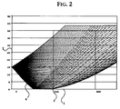
- FIG. 2 shows this “penumbra zone”, which lies to the right of the first beam reflected on the ground.
- the parabolic approximation accordingly provides both a direct beam and a second beam that passes through a caustic. This reflects Eq.
- a o1 and a o2 are calculated on the assumption that the starting point or source point is at ground level or at the height of the limit height parameter h v .
- the solution according to Eq. (3.11) differently curved rays before and after reflection.
- the condition can be introduced that both curvatures are the same. This has little influence on the result, but is numerically much easier to handle. This is explained in the section on calculation methods under the item reflections.
- ⁇ is the angle between the jet and the plane of the floor
- z is the floor impedance relative to the ambient air
- ⁇ e is the flow resistance in Ns ⁇ m -4
- ⁇ e is the effective rate of exponential change in the porosity of the floor
- f is the frequency in heart .
- the approach is based on a porous, locally reacting absorber.
- the reflection on the ground can be described with the reflection factor R for larger distances from the ground on the basis of plane waves. For smaller distances and heights above the ground, the spherical characteristics of the output wave and the reflected wave must also be taken into account.
- Table 5.1 shows that according to Eq. 5.6 over Eq. 5.1 absorption to be calculated on the floor. A maximum is observed in the low-frequency range between 2 and 3 degrees in relation to the plane, from 500 Hz the ground absorption increases with the angle. 6.
- the sound beams emitted by a source at a certain angle ⁇ can be passed through an enveloping lower surface r- ⁇ / 2 , and an upper surface through ⁇ + ⁇ / 2 given is described. If you cut these egg envelopes with a vertical surface that goes through the center of the source, you get an upper and a lower boundary line of the beam. We speak of caustics when these lines intersect. Since the upper boundary line is interchanged with the lower boundary line, going through caustics is connected with a 180 ° phase jump (see also: Arnold Sommerfeld, lectures on theoretical physics, B and IV, optics, Academic Publishing Company Geest & Portig K.-G ., Leipzig 1957).
- Single reflections are understood to be sound rays that after a reflection hit the ground at the point of impact. As long as the distance is too short between the source and the point or an insufficient curvature of the sound beams only a reflection occurs on the ground occur after the reflection on the ground no caustics on. From a certain distance, three single reflections observed, with the reflection in the middle between the point of transmission and transmission has a caustic. In the borderline case of the transition stand out because of the in the Kaustik occurring phase inversion two beams. The two rays can only be distinguished if the points of impact regarding the sufficiently differentiate the considered wavelength.
- caustics also occur in the penumbra in the penumbra if the curvature of the sound rays becomes sufficiently large ( ⁇ > 1 2- m ), without reflections on the floor.
- Eq. (7.6) can be used for a total of 4 beams with the different Time differences are generalized. The same applies to the consideration of Inconsistency according to the section on coherence.
- Wind speed and wind direction change over time with decreasing Stability the fluctuations become stronger. It is therefore not to be expected that when measuring in a particular meteorological situation, the calculated Levels can be found because the wind profile is already in the propagation distance changes. For a realistic comparison between calculation and Measurement is therefore the result at different wind speeds and averaging wind directions to provide a realistic baseline for measurements to obtain.
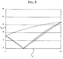
- the sound beam of the direct beam and the ground reflection is for one Spring height of 9.5 m and a point of incidence of 20 m for stability class V shown.
- Table 8.1 shows the geometric data on distance and time difference, Radii of curvature etc. compiled.
- the path of direct sound (Path 1) is 770.6 m, that of the reflected beam is 771.1 m.
- the covered Time that is calculated as a path integral over the speed of sound field is 2,258 or 2,260 s.
- the resulting actual displacement on Point of rise is 0.715 m and leads to a corresponding one depending on the frequency Phase shift.
- the level reduction dM of the direct beam caused by the non-linear change in the speed of sound with height is -0.5 dB.
- This level change is referred to as additional meteorological damping or meteorological measure.
- the beam reflected from the ground is reduced at an angle of incidence of 2.7 ° to the horizontal -2.0 dB and is composed of the absorption on the ground and the meteorological measurements of the incident and reflected beam, taking into account the mirror source sound strength Q.
- the ground absorption is frequency-dependent. In order to obtain a singular value, a linear frequency composition between 50 Hz and 1500 Hz was assumed and A-weighted. All changes in level relate to the A sound level.
- the energetic sum results (incoherent case ⁇ X ij >> 2) 1.2 dB and describes the case where the unevenness of the ground, turbulence etc. have destroyed the coherence between the beams.
- the radius of curvature of the direct sound is 41.12 km, that of the two parts of the beam reflected on the ground 23.8 and 11.95 km, ie the curvature of the reflected beam is larger on average than that of the direct beam. This corresponds to the expectation due to the course closer to the ground and explains that the ground reflectance is -2.6 dB, the mean ground absorption from 50 Hz to 1500 Hz is approx. -1 dB.
- the radii of curvature are sufficiently large to lead to a beam path that largely corresponds to the assumption of straight-line sound propagation (see FIG. 5).
- Table 8.1 and Figure 5 corresponds to a very unstable weather situation, such as occurs in strong sunlight. With a spread of 770 m, an average turbulent path deviation of 2.59 m is calculated according to TA Heil.
- D BM 3 - D BM (VDI 2714).
- the VDI 2714 delivers a D BM for longer distances of -1.8 dB.
- a level increase of between 1.2 and 1.6 dB occurs due to reflection on the floor.
- VDI 2714 there is a D BM of -1 dB, ie a level reduction.
- the soil meteorological measure is 16.9 dB, ie in the direction of the headwind and near the shadow zone, the sound beams are focused.
- the beam path deviates significantly from the beam path that would result if linear propagation were assumed.
- Both beams pass through the same layers of air at a very short distance and are therefore largely deflected by the air turbulence in the same way from the calculated path, ie the beams remain largely coherent despite the turbulence taken into account and are focused.
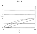
- FIG. 7 shows the case of a wind condition with stable weather conditions and a distance of 1770 m.
- the three reflections on the ground described in Appendix D VDI 2714 occur.
- the soil meteorological measure consists of 4 contributions to -0.7 dB (see Tab. 8.3). Due to the large time shifts between the beams, a resulting interference effect cannot be observed, ie the energetic sum of the 4 damping measures is also -0.7 dB (complete incoherence).
- this stability class results in a ground-level sound source an elliptical zone in which the source is directly perceptible is.
- a shadow zone forms in all directions out. So the same level outside the shadow zone can be found in approx. 350 m as well can also be measured at a distance of 1000 m, at a measuring height of 10 m above Reason. In between there is a minimum.
- the resulting interference cancellation according to VDI 2714 does not occur at longer distances in the direction of the wind with vertically extended sources.
- interference cancellation can be expected at the transition from the beginning of negative radii of curvature to the shadow zones.
- the result of this is that interference cancellation in the case of extensive sources cannot explain the additional attenuation at Mitwind D BM , which has been repeatedly confirmed by measurements, according to VDI 2714.
- the coherence condition for incoherent sources speaks very clearly against this (see also the section on coherence).
- the additional meteorological damping in the direction of the wind at larger distances can be explained as the interaction of defocusing due to the non-linear change in the speed of sound with the height and the frequency-dependent absorption of the sound when reflecting off the ground and when it is formed Bump. Occurrence of caustics when there is more than one floor reflection can cause local deviations, since the sound rays are subject to defocusing once they have passed through the caustics.
- the coherent case can also be used the incoherent case.
- Table 8.5 compares the level decreases according to VDI 2714 for a source height of 0.5 m and a point height of 4 m with the values for dBM that are obtained for stable, unstable and unstable weather conditions with the same geometry for the borderline cases of coherent and incoherent sound beams.
- a D BM of -2.4 dB is achieved at a distance of 2000 m in stable weather conditions, a coherent case is calculated in unstable conditions over -6 dB.
- the values in brackets describe the coherent case.
- the resulting ground interference effect is close to (coherent) 75 m -1.0 dB.
- Table 8.5 shows that this proportion is included in the VDI 2714 approach appears to be, i.e. the ground meteorological measure for a source close to the ground VDI 2714 is based on coherence of direct and reflected rays and describes the sound propagation in stable weather conditions. In larger ones Distances occur in any case significantly higher additional damping for the indifferent and unstable weather conditions.
- the coherent case is of the incoherent except indistinguishable in practice in the case of unstable weather conditions, since for larger ones Distances the coherent case and unstable weather conditions are unrealistic because of that the turbulence is great here.
- Table 8.6 compares the D BM according to VDI 2714 and for three weather conditions for a source height of 3.5 and a point height of 4 m (coherent approach). Averaged over 5 or 6 different wind speeds and over ⁇ 10 ° wind direction in the three weather conditions. The coherent case differs significantly from the incoherent one.
- the method according to the present invention provides the same value at 50 m distance as VDI 2714; at a distance of 200 m, the VDI 2714 predicts a decrease of 1 dB, at a distance of approx. 700 m the present technical procedure and the same values according to VDI 2714 deliver and at a distance of 2000 m the theory predicts a 1.6 dB higher D BM .
- the differences at close range and far range increase. For the far range, it is reasonable to assume that second-order reflections make further contributions and that the differences are somewhat smaller. However, it is in line with the observations of extensive industrial sources through long-term measurements that even at distances of 800 m or more during the day, the level is at least 1 dB lower on average than at mid-wind at night.
- the source delivers coherent and incoherent Approach 1.1 dB less than the VDI 2714. In all three cases this configuration the coherent and incoherent model very similar. At larger distances all weather conditions show less additional damping than the VDI 2714. The underestimation The additional attenuation at high sound sources is a common in practice observed phenomenon, however, because of the often still existing directional characteristic its impact is difficult to estimate.
- the deviations in the range up to 800 m are less than 2.4 dB, with increasing Remove the parabolic model at low altitudes higher additional damping predicts in stable weather conditions. Taking reflections into account higher order, the predicted additional damping is reduced by approx. 0.5 dB above 1000 m.
- VDI 2720 (noise protection by screening outdoors, Beuth-Verlag, Berlin, draft 1991) subtracts the D BM from the screen dimension when calculating the insertion loss of sound screens. This is done on the assumption that interference erasure cannot occur after the screen is set up. This is opposed to the fact that with the present model the interference component with the D BM up to a distance of 200 m is at most up to 1 dB. In addition, for distances over 200 m, the resulting interference in stable weather conditions is negligible. This means, especially for higher lying sound sources, that the D BM cannot be deducted. This is in line with the note in VDI 2720, which is based on practical experience with large industrial areas, that the deduction can be omitted for extensive industrial sources. This also suggests that in these cases the rays do not leave the sources coherently.
- the coherence requirement is for mobile sources close to the ground, such as road traffic according to the section on coherence. With heavy traffic, it can be assumed that that the turbulence generated by the traffic eliminates the interference reduced at close range.
- the present predicts in unstable situations; from Invention based on a parabolic model according to TA ships higher resulting Interference effects compared to stable weather conditions. This corresponds to the Nordic Model (see Appendix D VDI 2714).
- the VDI 2714 model represents sound propagation among those that are favorable for propagation Conditions for inversions at night. For the indifferent and unstable Weather conditions are calculated higher additional attenuation in the direction of the wind. This is confirmed by experience. That on the model developed here based method according to the present invention also allows the sound propagation and the additional meteorological attenuation in known Wind direction, wind speed and atmospheric stability (degree of coverage) to calculate.
- the ground impedance is required as additional information. The method according to the present invention was measured using a Ground impedances for grasslands tested. Other ground impedances that come from the flow resistance can be used.
- the frequency of wind direction, wind speed and stability can vary for Every location in Germany can be specified by the German Weather Service.
- German Weather Service With these data and the present model are climatological calculations the sound immission possible, which the frequencies of the different Consider weather conditions on a long-term average (10 years). This makes it possible the effect of sound screens in a climatological context bring, i.e. it opens up the possibility of showing how often what level reductions can be expected during the day and at night. Regional Differences that are climatic or geographical can be quantified will. You can follow the procedures for calculating the immission of non-atmospheric substances according to TA Lucas.
- m is determined by the dispersion class.
- Equation (B5) applies to positive radii of curvature
- equation (B6) applies to negative ones Radii of curvature.
- Equation (B6) There are two solutions to equation (B6).
- the shadow zone results from
- the limit of the shadow zone is through clearly determined.
- ⁇ can preferably also be selected with the value 2/3, based on the approach to adapting to the mean beam height.
- ⁇ is selected such that the mean reciprocal radius of curvature in the individual points of the sound beam over the entire sound beam, namely is equal to the reciprocal radius of curvature of the entire sound beam, that is applies, where is the mean radius of curvature in the individual points of the sound beam over the entire sound beam and R is the radius of curvature of the entire sound beam.
- R The radius of curvature R (z) over the course of the sound beam at a height z is according to Eq. 3.4 with given.
- R 2nd - x b 2nd (Ra 0 ) 2nd can be scheduled.
- R 2nd - x b 2nd (R - a 0 ) 2nd
- R 2nd - x b 2nd a 0 2nd - 2 a 0 R
- R 2nd -x b 2nd a 0 2nd - 2 a 0 R
- ⁇ can preferably also be experimented in this way be determined.
- the Points are determined by the condition that the angle of incidence is equal to the angle of reflection is determined.
- the curvature of the sound beams for the partial beams can be calculated individually be, or the curvature is set the same for both beams, with each the curvature of the longer beam is always used. The calculations show that the different approaches have little impact have additional damping due to meteorological reasons.
- z 1 ' is the first deflection of the first beam on the ground at point x
- z 2 ' is defined accordingly. It has proven to be advantageous to approximate these interpolation points by means of a third-order polygon and to search for the zeros at which the reflection condition is fulfilled. The advantage of this approach is that it works even on uneven terrain.
- An algorithm in which the zero point has proven to be a fast algorithm is determined by halving the search interval.
- n stands for the number of ground reflections and a is an unknown constant.
- the system of equations can be numerically easily determined using an algorithm determine one zero each. There are basically 4 Solutions to an n, with a maximum of 3 real solutions.
- the cases in between are calculated by iteration, for example using Newton 's algorithm.
- the second solution is between a O ' + h ' ⁇ 0 and H ' + a O ⁇ ⁇ > 0.
- the radiation becomes coherent, although the source, eg a fixed star, radiates incoherently.
- the condition for coherence is: x ⁇ sin ( ⁇ ) ⁇ / 4 where x is the dimension of the source and ⁇ is the wavelength and ⁇ the aperture angle at which the source is observed.
- the methods and devices according to the invention allow this not only easy to determine the sound rays, but also the focusing and defocusing generated by the wind and temperature field without further numerical differentiation incl. by reflection on the ground caused interference taking into account the atmospheric turbulence to determine.
- the determination can advantageously be carried out with the aid of the present invention the sound immission with known spatial structure of the sound sources for a meteorological situation based on the wind direction, wind speed and stability class.
- This application is extremely useful to check on the basis of a few sound immission measurements whether the method is correct for the applied or measured sound emissions. So that Reliability of measurements to check whether commercial businesses meet the immission guidelines adhere to, be simplified considerably.
- the wind direction in a river valley often follows the direction of flow at night of the water. This is the probability of a wind situation with noise barriers or walls that are parallel to the river, much less than on a road that is transverse to the direction of flow. Such differences that are can have a significant impact, for example according to the present invention be taken into account.
- Fig. 1 shows the parameters of the parabolic approach.
- the distance 1 is plotted on the x-axis, whereas the y-axis indicates the height 2 .
- s 1 and s 2 are the openings of the beams at constant and not constant speed of sound.
- Fig. 2 shows a numerical solution for the headwind direction.
- the sound source is at a height of 15 m.
- the distance in meters 1 is plotted on the x-axis, whereas the y-axis indicates the height in meters 2 .
- a zone between shadows and rays with ground reflection can also be seen.
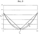
- the path difference is -0.06 m.
- the distance 1 is plotted on the x-axis, whereas the y-axis indicates the height 2 .
- Fig. 5 shows a direct beam and reflection on the ground at a source height of 9.5 m and an incidence height of 20 m.
- the distance 1 is plotted on the x-axis, the height 2 is indicated on the y-axis.
Landscapes
- Physics & Mathematics (AREA)
- General Physics & Mathematics (AREA)
- Measurement Of Velocity Or Position Using Acoustic Or Ultrasonic Waves (AREA)
- Geophysics And Detection Of Objects (AREA)
- Diaphragms For Electromechanical Transducers (AREA)
Applications Claiming Priority (2)
| Application Number | Priority Date | Filing Date | Title |
|---|---|---|---|
| DE19638537 | 1996-09-20 | ||
| DE19638537 | 1996-09-20 |
Publications (3)
| Publication Number | Publication Date |
|---|---|
| EP0831310A2 true EP0831310A2 (fr) | 1998-03-25 |
| EP0831310A3 EP0831310A3 (fr) | 1999-07-28 |
| EP0831310B1 EP0831310B1 (fr) | 2002-12-11 |
Family
ID=7806313
Family Applications (1)
| Application Number | Title | Priority Date | Filing Date |
|---|---|---|---|
| EP97116062A Expired - Lifetime EP0831310B1 (fr) | 1996-09-20 | 1997-09-16 | Procédé et dispositif pour déterminer l'atténuation additionnel météorologique du son |
Country Status (3)
| Country | Link |
|---|---|
| EP (1) | EP0831310B1 (fr) |
| AT (1) | ATE229643T1 (fr) |
| DE (2) | DE19740783C2 (fr) |
Cited By (3)
| Publication number | Priority date | Publication date | Assignee | Title |
|---|---|---|---|---|
| EP2071305A3 (fr) * | 2007-12-06 | 2010-11-17 | Manfred T. Kalivoda | Procédé de détermination de seuils d'émissions sonores |
| CN111693139A (zh) * | 2020-06-19 | 2020-09-22 | 浙江讯飞智能科技有限公司 | 声音强度测量方法、装置、设备及存储介质 |
| CN121500450A (zh) * | 2026-01-13 | 2026-02-10 | 中国气象局地球系统数值预报中心 | 地形湍流拖曳力的拖曳系数确定方法、装置、设备及介质 |
Family Cites Families (1)
| Publication number | Priority date | Publication date | Assignee | Title |
|---|---|---|---|---|
| DE3805778A1 (de) * | 1988-02-24 | 1989-08-31 | Fraunhofer Ges Forschung | Verfahren und vorrichtung zur erfassung und ueberwachung der meteorologisch bedingten uebertragungsverhaeltnisse von laerm |
-
1997
- 1997-09-16 DE DE19740783A patent/DE19740783C2/de not_active Expired - Fee Related
- 1997-09-16 EP EP97116062A patent/EP0831310B1/fr not_active Expired - Lifetime
- 1997-09-16 AT AT97116062T patent/ATE229643T1/de not_active IP Right Cessation
- 1997-09-16 DE DE59708931T patent/DE59708931D1/de not_active Expired - Fee Related
Non-Patent Citations (5)
| Title |
|---|
| LAMANCUSA J S ET AL: "RAY TRACING IN A MOVING MEDIUM WITH TWO-DIMENSIONAL SOUND-SPEED VARIATION AND APPLICATION TO SOUND PROPAGATION OVER TERRAIN DISCONTINUITIES" JOURNAL OF THE ACOUSTICAL SOCIETY OF AMERICA, Bd. 93, Nr. 4 PT 01, 1. April 1993, Seiten 1716-1726, XP000363142 * |
| LEHN W H: "A simple parabolic model for the optics of the atmospheric surface layer" APPLIED MATHEMATICAL MODELLING (UK), Bd. 9, Nr. 6, Dezember 1985, Seiten 447-453, XP002104129 * |
| RASPET R ET AL: "THE EFFECT OF REALISTIC GROUND IMPEDANCE ON THE ACCURACY OF RAY TRACING" JOURNAL OF THE ACOUSTICAL SOCIETY OF AMERICA, Bd. 97, Nr. 1, 1. Januar 1995, Seiten 154-158, XP000611042 * |
| VDI RICHTLINIEN 2714: "Schallausbreitung im Freien" Januar 1988 , VDI-VERLAG GMBH , D]SSELDORF XP002104130 * Seite 6 - Seite 7 * * |
| WALKDEN F, WEST M: "Prediction of enhancement factor for small explosive sources in a stratified moving atmosphere" JOURNAL OF THE ACOUSTICAL SOCIETY OF AMERICA, Bd. 84, Nr. 1, Juli 1988, Seiten 321-326, XP002104128 * |
Cited By (3)
| Publication number | Priority date | Publication date | Assignee | Title |
|---|---|---|---|---|
| EP2071305A3 (fr) * | 2007-12-06 | 2010-11-17 | Manfred T. Kalivoda | Procédé de détermination de seuils d'émissions sonores |
| CN111693139A (zh) * | 2020-06-19 | 2020-09-22 | 浙江讯飞智能科技有限公司 | 声音强度测量方法、装置、设备及存储介质 |
| CN121500450A (zh) * | 2026-01-13 | 2026-02-10 | 中国气象局地球系统数值预报中心 | 地形湍流拖曳力的拖曳系数确定方法、装置、设备及介质 |
Also Published As
| Publication number | Publication date |
|---|---|
| EP0831310A3 (fr) | 1999-07-28 |
| ATE229643T1 (de) | 2002-12-15 |
| DE19740783A1 (de) | 1998-04-02 |
| EP0831310B1 (fr) | 2002-12-11 |
| DE59708931D1 (de) | 2003-01-23 |
| DE19740783C2 (de) | 2000-08-31 |
Similar Documents
| Publication | Publication Date | Title |
|---|---|---|
| EP2917763B1 (fr) | Système de mesure lidar et procédé de mesure lidar | |
| EP3343249B1 (fr) | Procédé d'augmentation de la résolution spatiale d'une prévision météorologique | |
| EP0521855B1 (fr) | Amelioration apportee a un debitmetre aux ultrasons pour gaz et liquides | |
| DE102009041044A1 (de) | Vorrichtung und Computerprogramm zur Ermittlung von Funkwellenausbreitungs-Charakteristiken | |
| DE19835797C2 (de) | Verfahren zur Erfassung von Rauch mittels eines Lidar-Systems | |
| AT509215B1 (de) | Laser-hydrographieverfahren | |
| DE112021006609T5 (de) | Vorhersage des senkrechten abstands von schwingungen durch verteilte faseroptische abtastung | |
| DE4037156A1 (de) | Radarantennenanordnung | |
| DE3808173A1 (de) | System zum detektieren unterirdischer objekte | |
| DE102008023862A1 (de) | Vorrichtung und Verfahren zur Erzeugung eines Ultraschallbildes | |
| EP1085346B1 (fr) | Procédé pour mesurer la distance d'un objet, de particules atmospheriques et similaires utilisant des signaux de Lidar ou Radar à laser | |
| WO2010025712A1 (fr) | Procédé pour évaluer des valeurs mesurées d'un capteur optique de distance | |
| EP0157153A1 (fr) | Procédé de simulation de radar | |
| EP1592984B1 (fr) | Procede pour determiner des types de precipitation dans l'atmosphere | |
| DE102020122990A1 (de) | Verfahren und Vorrichtungen zur Simulation elektromagnetischer Strahlen | |
| EP0831310B1 (fr) | Procédé et dispositif pour déterminer l'atténuation additionnel météorologique du son | |
| EP2290397B1 (fr) | Procédé de mesure destiné à l'analyse non destructive d'une couche de neige et dispositif de mesure destiné à l'exécution du procédé de mesure | |
| EP2531822A2 (fr) | Procédé de mesure de la profondeur d'une nappe d'eau | |
| DE10001015C2 (de) | Verfahren zur Messung der Entfernung von Objekten, atmosphärischen Partikeln und dergleichen mittels Lidar- oder Laserradar-Signalen | |
| EP1889092B1 (fr) | Procede et dispositif pour corriger des donnees meteorologiques et progiciel informatique correspondant | |
| EP2921879B1 (fr) | Procédé de classification de points de mesure d'un jeu de données topo-bathymétrique | |
| DE102023113349A1 (de) | Verfahren zum Bestimmen einer vertikalen Struktur eines halbtransparenten Mediums aus SAR-Daten eines SAR-Systems | |
| DE19740083C1 (de) | Radarortungsgerät und Verfahren zur Bestimmung der Lage und Ausdehnung von verdeckten Objekten | |
| DE102020102851A1 (de) | Prüfvorrichtung zum Test eines mit Ultraschallwellen arbeitenden Abstandssensors | |
| DE2607169A1 (de) | Verfahren und messanordnung zur bestimmung des konzentrationsprofils von luftverunreinigungen oder natuerlichen bestandteilen in der atmosphaere |
Legal Events
| Date | Code | Title | Description |
|---|---|---|---|
| PUAI | Public reference made under article 153(3) epc to a published international application that has entered the european phase |
Free format text: ORIGINAL CODE: 0009012 |
|
| AK | Designated contracting states |
Kind code of ref document: A2 Designated state(s): AT DE DK FR GB SE |
|
| PUAL | Search report despatched |
Free format text: ORIGINAL CODE: 0009013 |
|
| AK | Designated contracting states |
Kind code of ref document: A3 Designated state(s): AT BE CH DE DK ES FI FR GB GR IE IT LI LU MC NL PT SE |
|
| 17P | Request for examination filed |
Effective date: 19991222 |
|
| AKX | Designation fees paid |
Free format text: AT DE FR GB |
|
| RBV | Designated contracting states (corrected) |
Designated state(s): AT DE DK FR GB SE |
|
| 17Q | First examination report despatched |
Effective date: 20010403 |
|
| GRAG | Despatch of communication of intention to grant |
Free format text: ORIGINAL CODE: EPIDOS AGRA |
|
| GRAG | Despatch of communication of intention to grant |
Free format text: ORIGINAL CODE: EPIDOS AGRA |
|
| GRAG | Despatch of communication of intention to grant |
Free format text: ORIGINAL CODE: EPIDOS AGRA |
|
| GRAH | Despatch of communication of intention to grant a patent |
Free format text: ORIGINAL CODE: EPIDOS IGRA |
|
| GRAH | Despatch of communication of intention to grant a patent |
Free format text: ORIGINAL CODE: EPIDOS IGRA |
|
| GRAH | Despatch of communication of intention to grant a patent |
Free format text: ORIGINAL CODE: EPIDOS IGRA |
|
| GRAA | (expected) grant |
Free format text: ORIGINAL CODE: 0009210 |
|
| AK | Designated contracting states |
Kind code of ref document: B1 Designated state(s): AT DE DK FR GB SE |
|
| REF | Corresponds to: |
Ref document number: 229643 Country of ref document: AT Date of ref document: 20021215 Kind code of ref document: T |
|
| REG | Reference to a national code |
Ref country code: GB Ref legal event code: FG4D Free format text: NOT ENGLISH |
|
| REF | Corresponds to: |
Ref document number: 59708931 Country of ref document: DE Date of ref document: 20030123 |
|
| GBT | Gb: translation of ep patent filed (gb section 77(6)(a)/1977) |
Effective date: 20030203 |
|
| PG25 | Lapsed in a contracting state [announced via postgrant information from national office to epo] |
Ref country code: SE Free format text: LAPSE BECAUSE OF FAILURE TO SUBMIT A TRANSLATION OF THE DESCRIPTION OR TO PAY THE FEE WITHIN THE PRESCRIBED TIME-LIMIT Effective date: 20030311 Ref country code: DK Free format text: LAPSE BECAUSE OF FAILURE TO SUBMIT A TRANSLATION OF THE DESCRIPTION OR TO PAY THE FEE WITHIN THE PRESCRIBED TIME-LIMIT Effective date: 20030311 |
|
| ET | Fr: translation filed | ||
| PLBE | No opposition filed within time limit |
Free format text: ORIGINAL CODE: 0009261 |
|
| STAA | Information on the status of an ep patent application or granted ep patent |
Free format text: STATUS: NO OPPOSITION FILED WITHIN TIME LIMIT |
|
| 26N | No opposition filed |
Effective date: 20030912 |
|
| PGFP | Annual fee paid to national office [announced via postgrant information from national office to epo] |
Ref country code: FR Payment date: 20040917 Year of fee payment: 8 |
|
| PGFP | Annual fee paid to national office [announced via postgrant information from national office to epo] |
Ref country code: AT Payment date: 20040922 Year of fee payment: 8 |
|
| PGFP | Annual fee paid to national office [announced via postgrant information from national office to epo] |
Ref country code: GB Payment date: 20041008 Year of fee payment: 8 |
|
| PG25 | Lapsed in a contracting state [announced via postgrant information from national office to epo] |
Ref country code: GB Free format text: LAPSE BECAUSE OF NON-PAYMENT OF DUE FEES Effective date: 20050916 Ref country code: AT Free format text: LAPSE BECAUSE OF NON-PAYMENT OF DUE FEES Effective date: 20050916 |
|
| GBPC | Gb: european patent ceased through non-payment of renewal fee |
Effective date: 20050916 |
|
| PG25 | Lapsed in a contracting state [announced via postgrant information from national office to epo] |
Ref country code: FR Free format text: LAPSE BECAUSE OF NON-PAYMENT OF DUE FEES Effective date: 20060531 |
|
| REG | Reference to a national code |
Ref country code: FR Ref legal event code: ST Effective date: 20060531 |
|
| PGFP | Annual fee paid to national office [announced via postgrant information from national office to epo] |
Ref country code: DE Payment date: 20070813 Year of fee payment: 11 |
|
| PG25 | Lapsed in a contracting state [announced via postgrant information from national office to epo] |
Ref country code: DE Free format text: LAPSE BECAUSE OF NON-PAYMENT OF DUE FEES Effective date: 20090401 |