EP0831406A2 - Implementierung eines Arbeitsflussmotors in einem Datenbankverwaltungssystem - Google Patents
Implementierung eines Arbeitsflussmotors in einem Datenbankverwaltungssystem Download PDFInfo
- Publication number
- EP0831406A2 EP0831406A2 EP97111729A EP97111729A EP0831406A2 EP 0831406 A2 EP0831406 A2 EP 0831406A2 EP 97111729 A EP97111729 A EP 97111729A EP 97111729 A EP97111729 A EP 97111729A EP 0831406 A2 EP0831406 A2 EP 0831406A2
- Authority
- EP
- European Patent Office
- Prior art keywords
- wfms
- dbms
- control
- function
- state
- Prior art date
- Legal status (The legal status is an assumption and is not a legal conclusion. Google has not performed a legal analysis and makes no representation as to the accuracy of the status listed.)
- Ceased
Links
Images


Classifications
-
- G—PHYSICS
- G06—COMPUTING OR CALCULATING; COUNTING
- G06Q—INFORMATION AND COMMUNICATION TECHNOLOGY [ICT] SPECIALLY ADAPTED FOR ADMINISTRATIVE, COMMERCIAL, FINANCIAL, MANAGERIAL OR SUPERVISORY PURPOSES; SYSTEMS OR METHODS SPECIALLY ADAPTED FOR ADMINISTRATIVE, COMMERCIAL, FINANCIAL, MANAGERIAL OR SUPERVISORY PURPOSES, NOT OTHERWISE PROVIDED FOR
- G06Q10/00—Administration; Management
- G06Q10/10—Office automation; Time management
Definitions
- the present invention relates to the field of implementation of workflow management systems (WFMS) on computer systems.
- WFMS workflow management systems
- WFMS Workflow-Management-Systems
- the "IBM FlowMark for OS/2" represents a typical modern, sophisticated, and powerful workflow management system. It supports the modelling of business processes as a network of activities.
- This network of activities, the process model is constructed as a directed, acyclic, weighted, colored graph.
- the nodes of the graph represent the activities or workitems which are performed.
- the edges of the graph, the control connectors describe the potential sequence of execution of the activities.
- Definition of the process graph is via the IBM FlowMark Definition Language (FDL) or the built-in graphical editor.
- the runtime component of the workflow manager interprets the process graph and distributes the execution of activities to the right person at the right place, e. g. by assigning tasks to a work list according to the respective person, wherein said work list is stored as digital data within said workflow or process management computer system.
- the business processes have to be analyzed and, as the result of this analysis, a process model has to be constructed as a network of activities corresponding to the business process.
- a process model In the IBM FlowMark product, the process models are not transformed into an executable.
- an instance of the process is created from the process model, called a process instance. This process instance is then interpreted dynamically by the IBM FlowMark product.
- WFMS workflow management systems
- DBMS database management system
- RDBMS Relational database management system
- Stored procedures allow an application program to be run in two parts. One part runs on the client and the other on the server. This allows one call to a remote database to execute a procedure, that may represent several, repetitive accesses to the database.
- the server procedure at the database runs within the same transaction as the client application.
- WFMS Due to the distributed nature of executing process models by WFMS, due to the huge amount of WFMS state information because of potentially very complex process models, due to the potentially large number of simultaneous users of a WFMS and so forth WFMS are permanently faced with the problem of trying to improve their internal processing speed and throughput to deliver as much as possible of the computer systems' processing power to the business processes themselves.
- the invention is based on the objective to improve a WFMS's throughput and responsiveness. More particularly, the objective of the invention is to provide an improved WFMS internal handling of WFMS state information and the administration of that state information in DBMS.
- WFMS relational database management system
- DBMS database management system
- the WFMS control functions such as navigating through the process graph, performing staff resolution, invoking programs and many more access the WFMS state information in the database, make the appropriate computations, and store new state information in the database. Access to the database takes place via the appropriate SQL DBMS calls. According to the current invention and in contrary to the current state of the art WFMS control functions are no longer implemented within the WFMS system itself.
- the current invention teaches to implement the WFMS engines, encompassing a set of control functions, directly within the DBMS. Only stubs corresponding to these control functions are still implemented within the WFMS. The main purpose of these stubs is to request the services of the WFMS control function cores within the DBMS.
- the technique proposed by the current invention increases performance of WFMS significantly as the WFMS control functions mainly operate on and within those computer systems, namely the DBMS, which store the data on the WFMS state.
- DBMS database management system
- a WFMS control function performs a multitude of DBMS accesses.
- all DBMS access take place from within the WFMS control function core executed directly within the DBMS itself.
- Such an approach is advantageous as the network traffic is reduced significantly. Network access is required no longer for each DBMS access. A single network access is sufficient, namely the one to request the service of the WFMS control function core. Further performance benefits are achieved by reducing the number of process switches due to the WFMS control function core operating directly within the DBMS.
- WFMS Wired Fidelity
- claim 3 suggests implement all WFMS control functions with DBMS access within the DBMS.
- claim 4 suggests to transfer the invention into a three tier system structure encompassing a WFMS client computer system, a WFMS server computer system and a DBMS system.
- the current invention is illustrated based on IBM's FlowMark workflow management system. Of course any other WFMS could be used instead. Furthermore the current teaching applies also to any other type of system which offers WFMS functionalities not as a separate WFMS but within some other type of system.
- a WFMS may support both, the modeling of business processes and their execution.
- Modeling of a business process as a syntactical unit in a way that is directly supported by a software system is extremely desirable.
- the software system can also work as an interpreter basically getting as input such a model:
- the model called a process model
- Such a model of a business process can be perceived as a template for a class of similar processes performed within an enterprise; it is a schema describing all possible execution variants of a particular kind of business process.
- An instance of such a model and its interpretation represents an individual process, i.e. a concrete, context dependent execution of a variant prescribed by the model.
- a WFMSs facilitates the management of business processes.
- Activities are the fundamental elements of the meta model.
- An activity represents a business action that is from a certain perspective a semantical entity of its own. With the model of the business process it might have a fine-structure that is then represented in turn via a model, or the details of it are not of interest at all from a business process modeling point of view. Refinement of activities via process models allows for both, modeling business processes bottom-up and top-down.
- control connectors Since activities might not be executed arbitrarily they are bound together via control connectors .
- a control connector might be perceived as a directed edge between two activities; the activity at the connector's end point cannot start before the activity at the start point of the connector has finished (successfully).
- Control connectors model thus the potential flow of control within a business process model.
- transition condition is associated with each control connector. Parameters from output containers of activities having already produced their results are followed as parameters referenced in transition conditions. When at run time an activity terminates successfully all control connectors leaving this activity are determined and the truth value of the associated transition conditions is computed based on the actual values of their parameters. Only the end points of control connectors the transition conditions of which evaluated to TRUE are considered as activities that might be executed based on the actual context of the business process. Transition conditions model thus the context dependent actual flow of control within a business process (i.e. an instance of a model).
- FlowMark consists, at the coarsest level, of a build time component and a run time component.
- the build time component supports the modeling of business processes according to the meta model described above and the run time component supports the corresponding semantics. Both components are implemented in a client/server structure.
- the client delivers the interaction with the user via an object-oriented graphical interface, invokes local tools, and provides animation.
- the server maintains the database for process instances, navigates through the process graph, and assigns the activities to the proper resources.
- Process definition includes modeling of activities, control connectors between the activities, input/output container, and data connectors.
- a process is represented as a directed acyclic graph with the activities as nodes and the control/data connectors as the edges of the graph. The graph is manipulated via a built-in, event-driven, CUA compliant graphic editor.
- the data containers are specified as named data structures. These data structures themselves are specified via the DataStructureDefnition facility.
- FlowMark distinguishes three main types of activities: program activities, process activities, and blocks.
- Program activities are implemented through programs. The programs are registered via the Program Definition facility. Blocks contain the same constructs as processes, such as activities, control connectors etc. They are however not named and have their own exit condition. If the exit condition is not met, the block is started again.
- Process activities are implemented as processes. These subprocesses are defined separately as regular, named processes with all its usual properties. Process activities offer great flexibility for process definition. It not only allows to construct a process through permanent refinement of activities into program and process activities (top-down), but also to build a process out of a set of existing processes (bottom-up). In particular, process activities help to organize the modeling work if several process modeler are working together. It allows the team members to work independently on different activities. Program and process activities can be associated with a time limit. The time limit specifies how long the activity may take. If the time is exceeded, a designated person is notified. If this person does not react within another time limit, the process administrator is notified. It not only helps to recognize critical situation but also to detect process deficiencies as all notifications are recorded in an audit trail.
- Data Structures are names and are defined in terms of elementary data types, such as float, integer, or string and references to existing data structures.
- Managing data structures as separate entities has the advantage that all interfaces of activities and their implementations are managed consistently in one place (similar to header files in programming languages).
- Program Registration Facility All programs which implement program activities are defined via the Program Registration Facility. Registered for each program is the name of the program, its location, and the invocation string.
- the invocation string consists of the program name and the command string passed to the program.
- a process instance is started either via the graphical interface of via the callable process application programming interface.
- start activities are located, the proper people are determined, and the activities are posted onto the work list of the selected people. If a user selects the activity, the activity is executed and removed from the work list of any other user to whom the activity has been posted. After an activity has executed, its exit condition is evaluated. If not met, the activity is rescheduled for execution, otherwise all outgoing control connectors and the associated transition conditions are evaluated.
- a control connector is selected, if the condition evaluates to TRUE.
- the target activities of the selected control connectors are then evaluated. If their start conditions are true, they are posted to the work list of selected people.
- a process is considered terminated, if all end activities have completed. To make sure that all end activities finish, a death path analysis is performed. It removes all edges in the process graph which can never be reached due to failing transition conditions. All information about the current state of a process is stored in the database maintained by the server. This allows for forward recovery in the case of crashes.
- WFMS workflow management systems
- RDBMS relational database management system
- DBMS database management system
- the WFMS control functions such as navigating through the process graph, performing staff resolution, invoking programs and many more access the WFMS state information in the database, make the appropriate computations, and store new state information in the database. Access to the database takes place via the appropriate SQL DBMS calls.
- the WFMS control functions are implemented within the WFMS system itself.
- the collection of above mentioned control functions build the heart of a WFMS called the WFMS engine .
- a typical implementation of a certain WFMS control function on top of a RDBMS i.e. which makes use of the RDBMS, will be outlined in greater detail.
- the control function Start a Process Instance will be chosen for that objective.
- This control function is part of the WFMS navigator , the core piece of the WFMS engine.
- the WFMS navigator performs all actions associated with processing the process model.
- the navigator understands a set of messages resulting in the execution of certain control functions like:
- Each message results in the execution of a series of SQL calls.
- One of the messages for example is the request for starting a process instance.
- the navigator relies with all its operations on two sets of tables: build time tables and run time tables .
- the build time tables contain the static information determined during build time, such as process model information, staff directory, or program information.
- the run time tables contain the dynamic information determined during run time, such as the process instance information.
- the various table instances are stored within the RDBMS.
- Figure 1 shows the table structure of the main build time table, the Processes table, which contains one entry for each process model and serves as the anchor point for all build time tables.
- MID the key of the table, contains the process name, which uniquely identifies a process model. This key is referenced by build time and run time tables.
- the table contains all process model related information, such as whether an audit trail should be written or not.
- Figure 2 shows the table structure of the Activities build time table. An entry is maintained in the table for each activity in a process model; it is uniquely identified by the AID column. MID contains the identifier of the appropriate process model.
- the ActivityPos field contains an indicator about the relative position of the activity within the process model, such as whether the activity is a start or and end activity. This helps among others to quickly determine start activities when a process is started.
- the StaffAssignment field contains an SQL statement which is the SQL representation of the staff assignment. At run time, the SQL statement is executed dynamically to obtain those users, who should receive the activity as a work item.
- Figure 3 shows the table structure of the main run time table , the ProcessInstances table, which contains one entry per process instance.
- PID uniquely identifies each process instance.
- the appropriate process model identifier is stored in MID .
- State contains the actual state of the process instance, such as running, suspended, or terminated.
- Figure 4 shows table structure of the ActivityInstances table, which contains one entry for each activity instance.
- PID is the identifier of the process instance this activity instance belongs to, AID the identifier of the activity within the process model; both together uniquely identify an activity instance.
- State contains the current state of the activity instance, such as ready, active, or finished.
- Figure 5 shows the table structure of the work item table which is used to maintain the workitems associated with a particular activity of a process instance. One entry is maintained for each user who gets the activity assigned.
- Figure 6 shows the appropriate code fragment of the control function to start a process. According to the state of the art this control function would be implemented on that computer system acting as the WFMS. It is important to recognize the multitude of SQL statements resulting in a multitude of separate interactions between the WFMS and the potentially remote RDMS.
- Statement 1 retrieves the appropriate process model information from the Processes build time table.
- Statement 2 sets the process instance state to running, creates a unique process instance identifier, and inserts this information into the ProcessInstances table.
- Statement 5 starts a loop over all start activities.
- Statement 6 retrieves for each activity the appropriate staff resolution and the activity identifier.
- Statement 7 sets the activity instance state to active and inserts an appropriate entry for the activity instance into the ActivityInstances table.
- the staff resolution is maintained in the form of an SQL statement to access the staff database.
- This statement is then prepared for execution in statement 8.
- An appropriate cursor is defined in statement 9 to retrieve the user to be assigned, and then opened in statement 10.
- Statement 11 starts a loop to retrieve all user to whom the activity should be assigned as work item.
- Statement 12 fetches the appropriate user identifier and statement 13 inserts an appropriate entry into the WorkItems table.
- Statement 14 closes the cursor for retrieval of the assigned users. Processing of starting a process terminates with closing the cursor for retrieving the start activities.
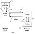
- Figure 7 shows how a normal database manager application 701 accesses a database 702 located on a database server. Each individual access 703, 704, 705 or 706, 707, 708 to the database must go across the network.
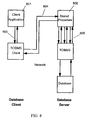
- FIG 8 shows the same application using the stored procedures technology.
- a stored procedure is a technique that allows an application 801 running on a client to call a procedure 802 physically stored on a database server.
- the server procedure 802 executes and accesses the database locally to the DBMS and returns information to the client application. This approach is especially advantageous if the stored procedures accesses the database multiple times. Under these circumstances a single access 803, 804 of the application 801 is required across the network while the repetitive databases accesses 805 can be executed in a performance effective manner directly within the database system.To use this technique, an application must be written in two separate procedures.
- the calling procedure 801 is contained in a client application and executes on the client.
- the server procedure 802 executes at the location of the database on the database server.
- the stored procedure 802 performs the processing on the database server, without transmitting unnecessary data across the network. Only those records are actually required at the client need to be transmitted.
- the server procedure at the database runs within the same transaction as the client.
- a stored procedure can also perform those DBMS features that exist only on the database server (but not on the database client), which includes commands to list directories, such as LIST DATABASE DIRECTORY and LIST NODE DIRECTORY.
- Stored procedures may execute in two different modes: fenced and non-fenced .
- a non-fenced procedure runs in the same address space as the database manager and results in increased performance when compared with a fenced stored procedure (which runs in an address space that is isolated from the database manager's). While performance improvements can be expected when running a non-fenced stored procedure, there is the danger that user code could accidentally damage the database control structures.
- a WFMS control function like the Start a Process Instance code fragment example for starting a process would then be implemented as two pieces.
- the new piece is the client piece 801, for which a fragment is shown in Figure 9.
- Statement 1 declares two host variables, procName to hold the name of the stored procedure which starts a process instance, and processModelId to hold the identifier (name) of the process model for which a process should be started.
- Statement 2 then calls the stored procedure startPrc and passes the name of the process model in parenthesis.
- this client piece of the WFMS control function is just a small stub representing the WFMS control function within the WFMS and which requests the associated service of the stored procedure within the DBMS to perform the service request and to deliver the actual processing results to a caller.
- the actual core of the WFMS control function is represented by the stored procedure 802 which is to a large extend identical to the code fragment of the control function Start a Process Instance visualized in Figure 6.
- the WFMS control function core is now no longer located within the WFMS but within the DBMS storing the WFMS state information.
- a further difference, not shown in the figures, is a piece of initialization code which accepts the passed host variable.
- FIG 10 shows simplified the overall structure of a WFMS according the state of the art.
- the WFMS represented by a certain control function 1001 acts as a client to the RDBMS 1002.
- Every WFMS control function, as shown in the previous chapter, consists of a series of SQL calls 1003 to 1004.
- This structure exhibits all the performance disadvantages discussed in the previous chapter as these SQL request have to be executed by passing system boundaries possibly involving communication across a computer network 1005 for each individual SQL request.
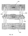
- WFMS control functions as stored procedures changes the structure of the WFMS implementation to the one depicted in Figure 11.
- a WFMS navigation step such as starting a process or finishing a workitem, is then implemented as a stored procedure which is called by the WFMS.
- a WFMS control function stub 1101 is requesting the service of an associated WFMS control function core 1102 no located within the RDMS 1103.
- all work is done in the database, minimal interaction and data passing between the WFMS and the RDBMS is required; all SQL calls are performed within the stored procedure, no containers, for example, have to be retrieved from the database into the WFMS workspace and stored back later into the database.
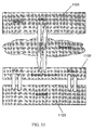
- FIG. 12 shows the system structure of a WFMS with a three tier structure encompassing a WFMS client 1201, a WFMS server 1202 and a RDBMS 1203. These structural components my be located on different computer systems or some of them may share the same physical computer system.
- the WFMS client on the user's workstation communicates with the WFMS server, which executes on a different workstation.
- the WFMS server accesses the RDBMS using the client interface 1204 provided by the RDBMS.
- the RDBMS itself may be on the same workstation as the WFMS server or on a different one.
- the WFMS and the RDBMS are exploiting a client/server structure.
- the current invention may be also applied to thus a system structure by implementing the WFMS control function stub on the WFMS client 1201 and the WFMS control function core on as stored procedure 1205 within the RDBMS.
Landscapes
- Engineering & Computer Science (AREA)
- Business, Economics & Management (AREA)
- Strategic Management (AREA)
- Entrepreneurship & Innovation (AREA)
- Human Resources & Organizations (AREA)
- Operations Research (AREA)
- Economics (AREA)
- Marketing (AREA)
- Data Mining & Analysis (AREA)
- Quality & Reliability (AREA)
- Tourism & Hospitality (AREA)
- Physics & Mathematics (AREA)
- General Business, Economics & Management (AREA)
- General Physics & Mathematics (AREA)
- Theoretical Computer Science (AREA)
- Information Retrieval, Db Structures And Fs Structures Therefor (AREA)
- Management, Administration, Business Operations System, And Electronic Commerce (AREA)
Priority Applications (1)
| Application Number | Priority Date | Filing Date | Title |
|---|---|---|---|
| EP97111729A EP0831406A3 (de) | 1996-09-11 | 1997-07-10 | Implementierung eines Arbeitsflussmotors in einem Datenbankverwaltungssystem |
Applications Claiming Priority (3)
| Application Number | Priority Date | Filing Date | Title |
|---|---|---|---|
| EP96114506 | 1996-09-11 | ||
| EP96114506 | 1996-09-11 | ||
| EP97111729A EP0831406A3 (de) | 1996-09-11 | 1997-07-10 | Implementierung eines Arbeitsflussmotors in einem Datenbankverwaltungssystem |
Publications (2)
| Publication Number | Publication Date |
|---|---|
| EP0831406A2 true EP0831406A2 (de) | 1998-03-25 |
| EP0831406A3 EP0831406A3 (de) | 2000-02-23 |
Family
ID=26142163
Family Applications (1)
| Application Number | Title | Priority Date | Filing Date |
|---|---|---|---|
| EP97111729A Ceased EP0831406A3 (de) | 1996-09-11 | 1997-07-10 | Implementierung eines Arbeitsflussmotors in einem Datenbankverwaltungssystem |
Country Status (1)
| Country | Link |
|---|---|
| EP (1) | EP0831406A3 (de) |
Cited By (5)
| Publication number | Priority date | Publication date | Assignee | Title |
|---|---|---|---|---|
| EP1069520A3 (de) * | 1999-07-13 | 2005-01-26 | Pfizer Products Inc. | Integriertes System und Verfahren für Geschäfts-Informationen |
| US6904161B1 (en) | 2000-11-17 | 2005-06-07 | Siemens Medical Solutions Usa | Workflow configuration and execution in medical imaging |
| US7865380B2 (en) * | 2001-11-08 | 2011-01-04 | International Business Machines Corporation | Automated information technology management system |
| WO2017148508A1 (en) | 2016-03-01 | 2017-09-08 | Huawei Technologies Co., Ltd. | Multi-phase high performance business process management engine |
| CN114240354A (zh) * | 2021-12-13 | 2022-03-25 | 武汉大学 | 基于数据库的教务工作流管理系统 |
Family Cites Families (1)
| Publication number | Priority date | Publication date | Assignee | Title |
|---|---|---|---|---|
| US5553234A (en) * | 1994-09-23 | 1996-09-03 | International Business Machines Corporation | System and method for including stored procedures, user-defined functions, and trigger processing in an existing unit of work |
-
1997
- 1997-07-10 EP EP97111729A patent/EP0831406A3/de not_active Ceased
Cited By (5)
| Publication number | Priority date | Publication date | Assignee | Title |
|---|---|---|---|---|
| EP1069520A3 (de) * | 1999-07-13 | 2005-01-26 | Pfizer Products Inc. | Integriertes System und Verfahren für Geschäfts-Informationen |
| US6904161B1 (en) | 2000-11-17 | 2005-06-07 | Siemens Medical Solutions Usa | Workflow configuration and execution in medical imaging |
| US7865380B2 (en) * | 2001-11-08 | 2011-01-04 | International Business Machines Corporation | Automated information technology management system |
| WO2017148508A1 (en) | 2016-03-01 | 2017-09-08 | Huawei Technologies Co., Ltd. | Multi-phase high performance business process management engine |
| CN114240354A (zh) * | 2021-12-13 | 2022-03-25 | 武汉大学 | 基于数据库的教务工作流管理系统 |
Also Published As
| Publication number | Publication date |
|---|---|
| EP0831406A3 (de) | 2000-02-23 |
Similar Documents
| Publication | Publication Date | Title |
|---|---|---|
| US5960420A (en) | Systems, methods and computer program products for implementing a workflow engine in database management system | |
| US6772407B1 (en) | Staging objects in workflow management systems | |
| US6122633A (en) | Subscription within workflow management systems | |
| US6415297B1 (en) | Parallel database support for workflow management systems | |
| US6308224B1 (en) | Method of generating an implementation of a workflow process model in an object environment | |
| US6631354B1 (en) | Deriving and running workload manager enclaves from workflows | |
| US6237020B1 (en) | Task-oriented automatic distribution of software | |
| US6073111A (en) | Container materialization/dematerialization for reduced dataload and improved data-coherency in workflow-management systems | |
| US6832201B1 (en) | Method and system for optimizing request shipping in workflow management systems | |
| US6820118B1 (en) | Method and system for providing a linkage between systems management systems and applications | |
| US6009405A (en) | Ensuring atomicity for a collection of transactional work items in a workflow management system | |
| US6826579B1 (en) | Generating event-condition-action rules from process models | |
| US6065009A (en) | Events as activities in process models of workflow management systems | |
| US6920456B2 (en) | Method, system, and program for maintaining information in database tables and performing operations on data in the database tables | |
| US7043714B2 (en) | Method, system, and program for using objects in data stores during execution of a workflow | |
| US5557793A (en) | In an object oriented repository, a method for treating a group of objects as a single object during execution of an operation | |
| US6278977B1 (en) | Deriving process models for workflow management systems from audit trails | |
| CN101097579B (zh) | 提供模型数据生成器的系统和方法 | |
| Alonso et al. | Workflow management: the next generation of distributed processing tools | |
| US20030004770A1 (en) | Method, system, and program for generating a workflow | |
| US20070288891A1 (en) | Meta-data driven implementation of business objects and their transactional behavior | |
| US7024670B1 (en) | Timed start-conditions for activities in workflow management systems | |
| US6507844B1 (en) | Method and system for minimizing network traffic | |
| US20020077945A1 (en) | Multiple audit trails in workflow-management-systems | |
| EP0895169A2 (de) | Ableitung von Prozessmodellen aus Rechnungsprüfvorgängen für Systeme zur Verwaltung von Arbeitsflüssen |
Legal Events
| Date | Code | Title | Description |
|---|---|---|---|
| PUAI | Public reference made under article 153(3) epc to a published international application that has entered the european phase |
Free format text: ORIGINAL CODE: 0009012 |
|
| AK | Designated contracting states |
Kind code of ref document: A2 Designated state(s): DE FR GB |
|
| AX | Request for extension of the european patent |
Free format text: AL;LT;LV;RO;SI |
|
| PUAL | Search report despatched |
Free format text: ORIGINAL CODE: 0009013 |
|
| AK | Designated contracting states |
Kind code of ref document: A3 Designated state(s): AT BE CH DE DK ES FI FR GB GR IE IT LI LU MC NL PT SE |
|
| AX | Request for extension of the european patent |
Free format text: AL;LT;LV;RO;SI |
|
| 17P | Request for examination filed |
Effective date: 20000516 |
|
| AKX | Designation fees paid |
Free format text: DE FR GB |
|
| STAA | Information on the status of an ep patent application or granted ep patent |
Free format text: STATUS: THE APPLICATION HAS BEEN REFUSED |
|
| 18R | Application refused |
Effective date: 20080912 |