EP0831428A2 - Machine postale - Google Patents
Machine postale Download PDFInfo
- Publication number
- EP0831428A2 EP0831428A2 EP97116467A EP97116467A EP0831428A2 EP 0831428 A2 EP0831428 A2 EP 0831428A2 EP 97116467 A EP97116467 A EP 97116467A EP 97116467 A EP97116467 A EP 97116467A EP 0831428 A2 EP0831428 A2 EP 0831428A2
- Authority
- EP
- European Patent Office
- Prior art keywords
- pulley
- print head
- envelope
- encoder
- endless belt
- Prior art date
- Legal status (The legal status is an assumption and is not a legal conclusion. Google has not performed a legal analysis and makes no representation as to the accuracy of the status listed.)
- Granted
Links
- 238000007639 printing Methods 0.000 claims abstract description 13
- 238000004891 communication Methods 0.000 claims abstract description 6
- 239000000463 material Substances 0.000 claims description 6
- 230000004044 response Effects 0.000 claims description 5
- 238000006073 displacement reaction Methods 0.000 claims description 2
- 230000003014 reinforcing effect Effects 0.000 description 5
- 238000004806 packaging method and process Methods 0.000 description 4
- 238000005516 engineering process Methods 0.000 description 3
- 238000007641 inkjet printing Methods 0.000 description 3
- 230000009471 action Effects 0.000 description 2
- 238000013461 design Methods 0.000 description 2
- 238000000034 method Methods 0.000 description 2
- 230000008569 process Effects 0.000 description 2
- 238000007651 thermal printing Methods 0.000 description 2
- 238000012546 transfer Methods 0.000 description 2
- 229920000271 Kevlar® Polymers 0.000 description 1
- 238000009825 accumulation Methods 0.000 description 1
- 238000003491 array Methods 0.000 description 1
- 238000005452 bending Methods 0.000 description 1
- 230000009286 beneficial effect Effects 0.000 description 1
- 230000008859 change Effects 0.000 description 1
- 230000006835 compression Effects 0.000 description 1
- 238000007906 compression Methods 0.000 description 1
- 238000012937 correction Methods 0.000 description 1
- 230000001419 dependent effect Effects 0.000 description 1
- 239000000835 fiber Substances 0.000 description 1
- 238000004519 manufacturing process Methods 0.000 description 1
- 239000002184 metal Substances 0.000 description 1
- 238000012986 modification Methods 0.000 description 1
- 230000004048 modification Effects 0.000 description 1
- 229920002635 polyurethane Polymers 0.000 description 1
- 239000004814 polyurethane Substances 0.000 description 1
- 238000007789 sealing Methods 0.000 description 1
- 230000007704 transition Effects 0.000 description 1
- 238000005303 weighing Methods 0.000 description 1
- 238000009736 wetting Methods 0.000 description 1
Images



Classifications
-
- G—PHYSICS
- G07—CHECKING-DEVICES
- G07B—TICKET-ISSUING APPARATUS; FARE-REGISTERING APPARATUS; FRANKING APPARATUS
- G07B17/00—Franking apparatus
- G07B17/00459—Details relating to mailpieces in a franking system
- G07B17/00467—Transporting mailpieces
-
- G—PHYSICS
- G07—CHECKING-DEVICES
- G07B—TICKET-ISSUING APPARATUS; FARE-REGISTERING APPARATUS; FRANKING APPARATUS
- G07B17/00—Franking apparatus
- G07B17/00185—Details internally of apparatus in a franking system, e.g. franking machine at customer or apparatus at post office
- G07B17/00193—Constructional details of apparatus in a franking system
-
- G—PHYSICS
- G07—CHECKING-DEVICES
- G07B—TICKET-ISSUING APPARATUS; FARE-REGISTERING APPARATUS; FRANKING APPARATUS
- G07B17/00—Franking apparatus
- G07B17/00185—Details internally of apparatus in a franking system, e.g. franking machine at customer or apparatus at post office
- G07B17/00314—Communication within apparatus, personal computer [PC] system, or server, e.g. between printhead and central unit in a franking machine
- G07B2017/00322—Communication between components/modules/parts, e.g. printer, printhead, keyboard, conveyor or central unit
-
- G—PHYSICS
- G07—CHECKING-DEVICES
- G07B—TICKET-ISSUING APPARATUS; FARE-REGISTERING APPARATUS; FRANKING APPARATUS
- G07B17/00—Franking apparatus
- G07B17/00459—Details relating to mailpieces in a franking system
- G07B17/00508—Printing or attaching on mailpieces
- G07B2017/00516—Details of printing apparatus
- G07B2017/00524—Printheads
- G07B2017/00532—Inkjet
Definitions
- the present invention relates generally to a mailing machine. More particularly, the invention relates to a mailing machine having a transport apparatus for feeding envelopes in continuous stream fashion past a print head for printing a postage indicia thereon.
- Mailing machines are well known in the art. Generally, mailing machines are readily available from manufactures such as Pitney Bowes, Stamford, CT. Mailing machines often include a variety of different modules which automate the processes of producing mailpieces.
- the typical mailing machine includes a variety of different modules or sub-systems where each module performs a different task on a mailpiece, such as: singulating (separating the mailpieces one at a time from a stack of mailpieces), weighing, sealing (wetting and closing the glued flap of an envelope), applying evidence of postage, accounting for postage used, feeding roll tape or cut tape strips for printing and stacking finished mailpieces.
- the exact configuration of each mailing machine is particular to the needs of the user.
- the mailing machine also includes a transport apparatus which feeds the mailpieces in a path of travel through the successive modules of the mailing machine.
- Postage meters may utilize a variety of different technologies to perform the printing process.
- Traditional postage meters use a rotary die that includes an embossed or raised surface in the pattern of the postal indicia. After applying ink to the die, the die is rotated to engage an envelope and transfer the ink from the embossed surface to the envelope to form the postal indicia.
- Other postage meters and printers use thermal printing technology to create the postal indicia on the envelope. In thermal printers, the envelope is compressed against a thermal print head by a print or platen roller with a thermal ink ribbon captured there between.
- the envelope and ink ribbon are simultaneously advanced past the thermal print head while the individual thermal print head elements are selectively heated causing the ink to liquefy and transfer to the envelope. Once printing is completed, it is necessary to feed the envelope from the postage meter.
- Still other postage meters and printers use ink jet printing technology to create the postal indicia.
- the envelope is brought to within a predetermined distance of the print head so that a desire print gap is established.
- the envelope is advanced past the ink jet print head while the individual print head elements, commonly referred to as nozzles, are selectively energized causing ink to be ejected from the print head and onto the envelope.
- the envelope could be held stationary while the print head traverses over the envelope as the nozzles are energized.
- a first type of prior art transport apparatus includes a motor, an encoder system coupled directly to the motor and a drive roller mounted to the output shaft of the motor.
- the transport apparatus is positioned with respect to the print head so that the drive roller is in opposing relationship to the print head elements. In this fashion, accurate encoding of the drive roller is ensured.
- this system generally works well, it creates packaging problems. Since the motor and print head are located in close proximity to each other, assuring adequate space for all the necessary components becomes difficult. Additionally, these types of systems are not well suited to mailing machines that must print over a wide print zone.
- a second type of prior art transport apparatus includes a motor, an encoder system coupled directly to the motor and a feed system operatively coupled to the output shaft of the motor.
- the feed system generally employs a belt looped around a series of pulleys and a series of gears connecting the pulleys to the output shaft of the motor.
- the motor is located remotely from the print head so that the packaging difficulties described above are alleviated. Additionally, the use of a belt allows for a longer transport path.
- this transport apparatus creates other problems. Because the encoder system is far removed from the print head, accurate tracking of the envelope is made difficult due to the accumulation of manufacturing tolerances and compliance of the components between the encoder system, the feed belt and the print head. Moreover, as the belt wears and stretches over time, the accuracy of the encoding will degrade further.
- a mailing machine comprising a control means, a print head having individual print elements which are selectively energizable for printing on an envelope and a transport means for feeding the envelope past the print head.
- the transport means including a first pulley, a second pulley in proximate location to the print head, an endless belt extending between the first and second pulley, the endless belt engaging the envelope and feeding the envelope past the print head, drive means for causing the endless belt to rotate and encoder means operatively coupled to the second pulley for providing signals indicative of the position of the second pulley.
- the control means is operative communication with the print head, the encoder means and the drive means for synchronizing the feeding of the envelope with energizing of the elements of the print head.
- Fig. 1 is a schematic representation of an elevational view of a partial mailing machine including a transport apparatus in accordance with the invention.
- Fig. 1A is a schematic representation of a plan view of an encoder pulley and an encoder system in accordance with the invention.
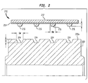
- Fig. 2 is a schematic representation of a cross sectional exploded end view of a belt and a pulley in accordance with the invention.
- Fig. 3 is a schematic representation of a cross sectional assembled end view of the belt and the pulley of Fig. 2 in accordance with the invention.
- a mailing machine 10 including a print head module 100, a transport apparatus 200 and a micro control system 300 is shown.
- the transport apparatus 200 feeds envelopes in a seriatim fashion in a path of travel along a deck 240 as indicated by arrow A past the print head module 100 so that an indicia of postage can be printed on each envelope 20.
- the print head module 100 is of an ink jet print head type having a plurality of ink jet nozzles (not shown) for ejecting droplets of ink in response to appropriate signals.
- the print head module 100 may be of any conventional type such as those commonly available from Hewlett-Packard Company and Canon Inc..
- the transport apparatus 200 includes an endless belt 210 looped around a drive pulley 220 and an encoder pulley 222 which is located downstream in the path of travel from the drive pulley 220 and proximate to the print head module 100.
- the drive pulley 220 and the encoder pulley 222 are substantially identical and are fixably mounted to shafts 244 and 246, respectively, which are in turn rotatively mounted to any suitable structure (not shown) such as a frame.
- the shaft 244 is operatively connected to a motor 260 by any conventional means such as intermeshing gears (not shown) or a timing belt (not shown) so that when the motor 260 rotates in response to signals from the micro control system 300, the drive pulley 220 also rotates which in turn causes the endless belt 210 to rotate and advance the envelope 20 along the path of travel.
- any conventional means such as intermeshing gears (not shown) or a timing belt (not shown) so that when the motor 260 rotates in response to signals from the micro control system 300, the drive pulley 220 also rotates which in turn causes the endless belt 210 to rotate and advance the envelope 20 along the path of travel.
- the transport apparatus 200 further includes a plurality of idler pulleys 232, a plurality of normal force rollers 234 and a tensioner pulley 230.
- the tensioner pulley 230 is initially spring biased and then locked in place by any conventional manner such as a set screw and bracket (not shown). This allows for constant and uniform tension on the endless belt 210. In this manner, the endless belt 210 will not slip on the drive pulley 220 when the motor 260 is energized and caused to rotate.
- the tensioner pulley 230 is rotatively mounted to one end 254a of an arm 254 while the other end 254b of the arm 254 is pivotally mounted to any suitable structure (not shown).
- An extension spring 256 is fixed at one end while the other end is mounted along the span of the arm 254 so as to bias the tensioner pulley 230 outward against the tensioner pulley 230.
- the idler pulleys 232 are rotatively mounted to any suitable structure (not shown) along the path of travel between the drive pulley 220 and the encoder pulley 222.
- the normal force rollers 234 are located in opposed relationship and biased toward the idler pulleys 232, the drive pulley 220 and the encoder pulley 222, respectively. Each normal force roller 234 is rotatively mounted to one end 250a of an arm 250 while the other end of the arm 254 is pivotally mounted to any suitable structure (not shown).
- a compression spring 252 is fixed at one end while the other end is mounted along the span of the arm 250 so as to bias the normal force roller 234 upward and into contact with the endless belt 210.
- the normal force rollers 234 work to bias the envelope 20 is up against the deck 240. This is commonly referred to as top surface registration which is beneficial for ink jet printing. Any variation in thickness of the envelope 20 is taken up by the deflection of the normal force rollers 234. Thus, a constant gap (the distance between the print head module 100 and the deck 240) is set between the envelope 20 and the print head module 100 no matter what the thickness of the envelope 20. The constant gap is optimally set to a desired value to achieve quality printing. It is important to note that the deck 240 contains suitable openings for the endless belt 210 and normal force rollers 234.
- the transport apparatus 200 also includes an encoder system 270 which is located proximate to the print head module 100 and operatively coupled to the encoder pulley 222.
- the encoder system 270 includes an encoder disk 272 fixably mount to the shaft 246 and an encoder detector 274 fixably mounted to a frame 280.
- the encoder disk 272 has a plurality of vanes located around its circumference and is of a conventional type, such as model number HP 5100 available from Hewlett-Packard Company.
- the encoder detector 274 is also of the conventional type, such as model number HP 9100 available from Hewlett-Packard Company, and includes a light source 274a and a light detector 274b.
- the encoder disk 272 and the encoder detector 274 are positioned with respect to each other so that the vanes of the encoder disk 272 alternately block and unblock the light source 274a as the shaft 246 rotates. The transition from blocked to unblocked or vice versa results in a change of state (also commonly referred to as a "count") for the encoder detector 274.
- the encoder disk 272 has been selected so that 1024 counts occur per revolution. In this manner, the position and speed of the shaft 246 can be tracked.
- This type of encoder system 270 is well known and those skilled in the art will recognize other means for encoding which would serve equally well.
- the print head module 100 includes a first row of nozzles 102 and a second row of nozzles 104 which may correspond to individual print heads which have been assembled together to form the print head module 100.
- the distance between the first row of nozzles 102 and the second row of nozzles 104 measured along the path of travel is necessary for packaging and performance considerations.
- high performance print head capable of high resolution printing at high speeds are only available in linear arrays of small length.
- to print a wide swath across the envelope 20 requires the alignment of multiple print heads in end to end fashion as measured in a direction transverse to the path of travel.
- the transport apparatus 200 and the print head module 100 as described above are under the control of the micro control system 300 which may be of any suitable combination of microprocessors, firmware and software.
- the micro control system 300 includes a motor controller 310 which is in operative communication with the motor 260 and a print head controller 320 which is in operative communication with the print head module 100. Additionally, the micro control system 300 is in operative communication with the encoder system 270 via the encoder detector 274.
- the micro control system 300 constantly compares the actual position of the envelope 20 with the desired position of the envelope 20 and computes appropriate corrective drive signals which are communicated to the motor controller 310.
- the motor controller 310 then provides energizing signals to the motor 260 in response to the drive signals received from the micro control system 300.
- the print head controller 320 provides energizing signals to the nozzles 102 and 104 of the print head module 100 in response to instructions from the micro control system 300.
- the micro control system 300 receives the counts from the encoder detector 274 as the encoder disk 272 alternately blocks and unblocks the encoder detector 274.
- the micro control system 300 instructs the print head controller 320 to energize the nozzles 102 and 104, appropriately. Thus, a line of print occurs for each count that takes place during printing.
- the endless belt 210 and the encoder pulley 222 are shown in more detail in a cross sectional end view in spaced apart relationship for clarity.
- the endless belt 210 includes an outer layer or main body 212, an inner layer comprised of a reinforcing cord 214 and a plurality of ribs 216 which extend outward from the reinforcing cord 214 a predetermined height H.
- the ribs 216 have a predetermined width RH at their root. Because the main body 212 is in contact with the envelope 20, it is made of a material such as polyurethane having a durometer of 35-70 to produce a suitably high coefficient of friction. This ensures no slippage between the endless belt 210 and the envelope 20.
- the reinforcing cord 214 serves to keep the endless belt 210 dimensionally stable by preventing the endless belt 210 from stretching. It may be made from any suitably strong material (high modulus of elasticity - to reduce stretch) which is also flexible enough to withstand repeated bending and tensile forces. For example, Kevlar®, which is readily available from Dupont, or metal fiber.
- the ribs 216 of the endless belt 210 fit into a plurality of corresponding grooves 224 of a predetermined depth D from the outside diameter 222a of the encoder pulley 222.
- the grooves 224 have a predetermined with GW at their opening.
- the drive pulley 220 and the idler pulleys 232 must also have grooves to accommodate the ribs 216 of the endless belt 210.
- the endless belt 210 and the encoder pulley 222 are shown in more detail in a cross sectional end view in their assembled positions.
- the height H of the ribs 216 is established to be less than the depth D of the grooves 224. This will ensure that the ribs 216 will not bottom out on the grooves 224 and cause the endless belt 210 to lift off from the encoder pulley 222.
- the reinforcing cord 214 of the endless belt 210 remains in intimate bearing contact with the outer diameter 222a of the encoder pulley 222.
- the endless belt 210 and the encoder pulley 222 are in driving engagement at the interface between the reinforcing cord 214 and the outer diameter 222a. Additionally, those skilled in the art will recognize that this arrangement provides for a constant pitch radius for the endless belt 210 as opposed to traditional V-type belts which sink further into their pulleys resulting in a shrinking pitch radius as the ribs wear.
- the pitch radius which is dependent upon the radius of the encoder pulley 222 and the thickness of the belt 210, is set to 0.679 inches.
- the micro control system 300 sends appropriate motor signals to the motor 260 via the motor controller 310 to cause the motor 260 to rotate which in turn causes the endless belt 210 to rotate and advance the envelope 20.
- the speed and/or position of the envelope 20 is set to a predetermined desire value such as the highest rate of feeding which would still produce a quality postal indicia.
- the micro control system 300 sends appropriate print signals to the print head module 100 via the print head controller 320 to cause the nozzles 102 and 104 to eject ink in a predetermined sequence at each encoder count to produce the postal indicia on the envelope 20.
- the micro control system 300 monitors the encoder signals from the encoder detector 274 and compares these signals to their expected signals. If the actual encoder signals do not match the expected encoder signals, then the envelope 20 is not feeding at the predetermined speed and the risk of a distorted postal indicia is present. At this point, if the actual encoder signals match the expected encoder signals, then the micro control system 300 continues to operate in normal fashion. However, if the actual encoder signals do not match the expected encoder signals, then the micro control system 300 may take one of two, or a combination of both, corrective actions.
- the micro control system 300 may adjust the motor signals so as to bring the bring the endless belt 210 into conformance with the predetermined belt speed.
- the motor controller 310 may adjust the print signals to account for the variance in the belt speed thus delaying or advancing the timing of the energizing of the print nozzles 102 and 104.
- the micro control system 300 only need take the first corrective action. Because printing is directly coupled to the actual position of the envelope 20 via the encoder counts, no correction is needed to produce the postal indicia without distortion. Thus, even if the envelope 20 is not being fed at the correct speed, or experiences wide variations in speed or position over the desired speed or position, a quality print will still result. This is because the sequence of the energizing of the nozzles 102 and 104 is tied to the actual position of the envelope 20 via the encoder counts.
Landscapes
- Physics & Mathematics (AREA)
- General Physics & Mathematics (AREA)
- Ink Jet (AREA)
- Handling Of Sheets (AREA)
- Handling Of Cut Paper (AREA)
- Character Spaces And Line Spaces In Printers (AREA)
Applications Claiming Priority (2)
| Application Number | Priority Date | Filing Date | Title |
|---|---|---|---|
| US717788 | 1996-09-23 | ||
| US08/717,788 US5740728A (en) | 1996-09-23 | 1996-09-23 | Mailing machine |
Publications (3)
| Publication Number | Publication Date |
|---|---|
| EP0831428A2 true EP0831428A2 (fr) | 1998-03-25 |
| EP0831428A3 EP0831428A3 (fr) | 2000-05-24 |
| EP0831428B1 EP0831428B1 (fr) | 2013-09-18 |
Family
ID=24883513
Family Applications (1)
| Application Number | Title | Priority Date | Filing Date |
|---|---|---|---|
| EP97116467.8A Expired - Lifetime EP0831428B1 (fr) | 1996-09-23 | 1997-09-22 | Machine postale |
Country Status (3)
| Country | Link |
|---|---|
| US (1) | US5740728A (fr) |
| EP (1) | EP0831428B1 (fr) |
| CA (1) | CA2215579C (fr) |
Cited By (2)
| Publication number | Priority date | Publication date | Assignee | Title |
|---|---|---|---|---|
| EP0871145A2 (fr) | 1997-03-27 | 1998-10-14 | Pitney Bowes Inc. | Machine postale ayant la capacité de déterminer la tarification en fonction des dimensions |
| CN106079854A (zh) * | 2012-05-18 | 2016-11-09 | 阪本顺 | 转印辊和印刷装置 |
Families Citing this family (15)
| Publication number | Priority date | Publication date | Assignee | Title |
|---|---|---|---|---|
| US6312072B1 (en) | 1997-05-01 | 2001-11-06 | Pitney Bowes Inc. | Disabling a printing mechanism in response to an out of ink condition |
| US5956051A (en) | 1997-05-29 | 1999-09-21 | Pitney Bowes Inc. | Disabling a mailing machine when a print head is not installed |
| US6041569A (en) * | 1997-07-11 | 2000-03-28 | Pitney Bowes Inc. | Mailing machine having envelope closing and sealing device |
| US5913627A (en) * | 1997-12-11 | 1999-06-22 | Pitney Bowes Inc. | Guide and support structure for a mailing machine |
| US6004048A (en) * | 1998-05-18 | 1999-12-21 | Pitney Bowes Inc. | Apparatus and method for ensuring good print quality in a mail handling system including a fixed printhead/moving mailpiece subsystem |
| US6062003A (en) * | 1998-11-18 | 2000-05-16 | Pitney Bowes Inc. | Sealing and deskewing device for a mailing machine |
| US6193825B1 (en) | 1998-12-28 | 2001-02-27 | Pitney Bowes Inc. | Method and apparatus for moistening envelope flaps |
| JP2000351477A (ja) * | 1999-06-11 | 2000-12-19 | Sharp Corp | 記録媒体搬送装置 |
| US6361603B1 (en) | 2000-05-18 | 2002-03-26 | Pitney Bowes Inc. | Apparatus for moistening envelope flaps |
| US6650077B1 (en) | 2001-06-27 | 2003-11-18 | Lexmark International, Inc. | Method for controlling printer paper feed |
| GB0118531D0 (en) * | 2001-07-30 | 2001-09-19 | Innovative Technology Ltd | Handling banknotes and the like |
| US20030056894A1 (en) * | 2001-09-25 | 2003-03-27 | John Getz | Applicator for adhesively-impregnated tape |
| JP3997990B2 (ja) * | 2002-03-08 | 2007-10-24 | ブラザー工業株式会社 | 画像形成装置及びそれに用いられる外側ベルト |
| TW552233B (en) * | 2002-08-29 | 2003-09-11 | Veutron Corp | A transmission mechanism of auto document feeder |
| US20060100046A1 (en) * | 2004-11-08 | 2006-05-11 | Canon Kabushiki Kaisha | Image forming apparatus |
Citations (1)
| Publication number | Priority date | Publication date | Assignee | Title |
|---|---|---|---|---|
| EP0718799A2 (fr) | 1994-12-22 | 1996-06-26 | Pitney Bowes Inc. | Machine à affranchir avec imprimente à jet d'encre |
Family Cites Families (15)
| Publication number | Priority date | Publication date | Assignee | Title |
|---|---|---|---|---|
| US4008801A (en) * | 1975-06-19 | 1977-02-22 | F. N. Shepard & Company | Guide for conveyor belt |
| US4225036A (en) * | 1977-09-06 | 1980-09-30 | Deere & Company | Endless belt conveyor |
| BE896737A (fr) * | 1982-06-01 | 1983-09-16 | Michelin & Cie Gen De S Ets Mi | Courroie de transmission de section trapezoidale |
| US4557372A (en) * | 1984-08-13 | 1985-12-10 | The Mead Corporation | Belt system with alignment apparatus |
| JPS62212640A (ja) * | 1986-03-14 | 1987-09-18 | Konishiroku Photo Ind Co Ltd | ハロゲン化銀写真感光材料 |
| NL8602967A (nl) * | 1986-11-21 | 1988-06-16 | Dunlop Enerka Bv | Transportband. |
| JPH02182641A (ja) * | 1988-12-30 | 1990-07-17 | Canon Inc | 画像記録装置 |
| US4959040A (en) * | 1989-04-21 | 1990-09-25 | Rastergraphics Inc. | Method and apparatus for precisely positioning and stabilizing a continuous belt or web or the like |
| FR2655752B1 (fr) * | 1989-12-08 | 1992-12-31 | Alcatel Satmam | Machine a affranchir a transporteur integre. |
| JPH05221548A (ja) * | 1992-02-14 | 1993-08-31 | Bando Chem Ind Ltd | 紙葉類搬送用無端ベルト |
| JPH06144626A (ja) * | 1992-11-10 | 1994-05-24 | Bando Chem Ind Ltd | 紙葉類搬送用無端ベルト |
| GB9224016D0 (en) * | 1992-11-16 | 1993-01-06 | Z Mark Int Inc | Mail stamping apparatus and method |
| US5544579A (en) * | 1992-12-17 | 1996-08-13 | Pitney Bowes Inc. | Mailing machine including overrideable sheet length discriminating structure |
| US5467709A (en) * | 1994-12-22 | 1995-11-21 | Pitney Bowes Inc. | Mailing machine utilizing ink jet printer |
| DE19605015C1 (de) * | 1996-01-31 | 1997-03-06 | Francotyp Postalia Gmbh | Vorrichtung zum Bedrucken eines auf einer Kante stehenden Druckträgers |
-
1996
- 1996-09-23 US US08/717,788 patent/US5740728A/en not_active Expired - Lifetime
-
1997
- 1997-09-15 CA CA002215579A patent/CA2215579C/fr not_active Expired - Fee Related
- 1997-09-22 EP EP97116467.8A patent/EP0831428B1/fr not_active Expired - Lifetime
Patent Citations (1)
| Publication number | Priority date | Publication date | Assignee | Title |
|---|---|---|---|---|
| EP0718799A2 (fr) | 1994-12-22 | 1996-06-26 | Pitney Bowes Inc. | Machine à affranchir avec imprimente à jet d'encre |
Cited By (3)
| Publication number | Priority date | Publication date | Assignee | Title |
|---|---|---|---|---|
| EP0871145A2 (fr) | 1997-03-27 | 1998-10-14 | Pitney Bowes Inc. | Machine postale ayant la capacité de déterminer la tarification en fonction des dimensions |
| CN106079854A (zh) * | 2012-05-18 | 2016-11-09 | 阪本顺 | 转印辊和印刷装置 |
| CN106079854B (zh) * | 2012-05-18 | 2018-12-07 | 阪本顺 | 转印辊和印刷装置 |
Also Published As
| Publication number | Publication date |
|---|---|
| EP0831428A3 (fr) | 2000-05-24 |
| US5740728A (en) | 1998-04-21 |
| CA2215579A1 (fr) | 1998-03-23 |
| EP0831428B1 (fr) | 2013-09-18 |
| CA2215579C (fr) | 2002-04-23 |
Similar Documents
| Publication | Publication Date | Title |
|---|---|---|
| US5740728A (en) | Mailing machine | |
| EP0911765B1 (fr) | Machine à affranchir à impression par jet d'encre et système de maintenance | |
| US6299269B1 (en) | Disabling a mailing machine when a print head is not installed | |
| EP0854445B1 (fr) | Appareil de transport d'articles | |
| US6106095A (en) | Mailing machine having registration of multiple arrays of print elements | |
| CA2250343E (fr) | Machine de traitement de courrier ayant un systeme d'impression a jet d'encre et un systeme d'entretien | |
| US6761425B2 (en) | Printing apparatus and printing method | |
| US6356883B1 (en) | Mailing system having flexible printing of messages | |
| EP1628833B1 (fr) | Fabrication de rubans de mesure | |
| EP0589722B1 (fr) | Machine d'affranchissement à impression thermique | |
| JP3131103B2 (ja) | シート搬送装置 | |
| CA2266292C (fr) | Machine a affranchir dote d'un systeme de prevention de perte de fonds | |
| EP1431925B1 (fr) | Méchanisme de transport pour une machine de traitement de courrier et procédé d'enregistrement d'un envoi postal dans une machine de traitement de courrier | |
| US7401913B2 (en) | Recording apparatus | |
| EP1780029A1 (fr) | Imprimante avec dispositif d'avance pour un support d'impression | |
| US5329302A (en) | Tapered platen roller for thermal printer | |
| US5923343A (en) | Mailing machine having a registration shield with improved air flow capability during ink jet printing on envelopes | |
| US5838346A (en) | Scanning printhead for printing on a moving medium | |
| GB2304635A (en) | Apparatus and method for positioning a printing mechanism between stations. | |
| US6062003A (en) | Sealing and deskewing device for a mailing machine | |
| JPH01233958A (ja) | 記録装置のシート送り方法 | |
| CA2501748C (fr) | Machine a affranchir dote d'un systeme de prevention de perte de fonds | |
| CA2425154A1 (fr) | Systeme de mise hors fonction d'une machine de traitement du courrier sans tete d'impression | |
| JPH09254466A (ja) | 記録材搬送装置 |
Legal Events
| Date | Code | Title | Description |
|---|---|---|---|
| PUAI | Public reference made under article 153(3) epc to a published international application that has entered the european phase |
Free format text: ORIGINAL CODE: 0009012 |
|
| AK | Designated contracting states |
Kind code of ref document: A2 Designated state(s): DE FR GB |
|
| PUAL | Search report despatched |
Free format text: ORIGINAL CODE: 0009013 |
|
| AK | Designated contracting states |
Kind code of ref document: A3 Designated state(s): AT BE CH DE DK ES FI FR GB GR IE IT LI LU MC NL PT SE |
|
| 17P | Request for examination filed |
Effective date: 20001113 |
|
| AKX | Designation fees paid |
Free format text: DE FR GB |
|
| GRAP | Despatch of communication of intention to grant a patent |
Free format text: ORIGINAL CODE: EPIDOSNIGR1 |
|
| INTG | Intention to grant announced |
Effective date: 20130411 |
|
| GRAS | Grant fee paid |
Free format text: ORIGINAL CODE: EPIDOSNIGR3 |
|
| GRAA | (expected) grant |
Free format text: ORIGINAL CODE: 0009210 |
|
| RIN1 | Information on inventor provided before grant (corrected) |
Inventor name: DEBARBER, CHRISTOPHER Inventor name: FREEMAN, GERALD |
|
| AK | Designated contracting states |
Kind code of ref document: B1 Designated state(s): DE FR GB |
|
| REG | Reference to a national code |
Ref country code: GB Ref legal event code: FG4D |
|
| REG | Reference to a national code |
Ref country code: DE Ref legal event code: R096 Ref document number: 69740655 Country of ref document: DE Effective date: 20131107 |
|
| REG | Reference to a national code |
Ref country code: DE Ref legal event code: R097 Ref document number: 69740655 Country of ref document: DE |
|
| PLBE | No opposition filed within time limit |
Free format text: ORIGINAL CODE: 0009261 |
|
| STAA | Information on the status of an ep patent application or granted ep patent |
Free format text: STATUS: NO OPPOSITION FILED WITHIN TIME LIMIT |
|
| 26N | No opposition filed |
Effective date: 20140619 |
|
| REG | Reference to a national code |
Ref country code: DE Ref legal event code: R097 Ref document number: 69740655 Country of ref document: DE Effective date: 20140619 |
|
| REG | Reference to a national code |
Ref country code: FR Ref legal event code: PLFP Year of fee payment: 19 |
|
| PGFP | Annual fee paid to national office [announced via postgrant information from national office to epo] |
Ref country code: GB Payment date: 20150928 Year of fee payment: 19 |
|
| PGFP | Annual fee paid to national office [announced via postgrant information from national office to epo] |
Ref country code: FR Payment date: 20150917 Year of fee payment: 19 |
|
| PGFP | Annual fee paid to national office [announced via postgrant information from national office to epo] |
Ref country code: DE Payment date: 20150929 Year of fee payment: 19 |
|
| REG | Reference to a national code |
Ref country code: DE Ref legal event code: R119 Ref document number: 69740655 Country of ref document: DE |
|
| GBPC | Gb: european patent ceased through non-payment of renewal fee |
Effective date: 20160922 |
|
| REG | Reference to a national code |
Ref country code: FR Ref legal event code: ST Effective date: 20170531 |
|
| PG25 | Lapsed in a contracting state [announced via postgrant information from national office to epo] |
Ref country code: DE Free format text: LAPSE BECAUSE OF NON-PAYMENT OF DUE FEES Effective date: 20170401 Ref country code: FR Free format text: LAPSE BECAUSE OF NON-PAYMENT OF DUE FEES Effective date: 20160930 Ref country code: GB Free format text: LAPSE BECAUSE OF NON-PAYMENT OF DUE FEES Effective date: 20160922 |