EP0831466A2 - Optical head having multiple light sources having different wavelengths - Google Patents
Optical head having multiple light sources having different wavelengths Download PDFInfo
- Publication number
- EP0831466A2 EP0831466A2 EP97402199A EP97402199A EP0831466A2 EP 0831466 A2 EP0831466 A2 EP 0831466A2 EP 97402199 A EP97402199 A EP 97402199A EP 97402199 A EP97402199 A EP 97402199A EP 0831466 A2 EP0831466 A2 EP 0831466A2
- Authority
- EP
- European Patent Office
- Prior art keywords
- light
- wavelength
- collimated light
- optical
- optical system
- Prior art date
- Legal status (The legal status is an assumption and is not a legal conclusion. Google has not performed a legal analysis and makes no representation as to the accuracy of the status listed.)
- Granted
Links
Images


Classifications
-
- G—PHYSICS
- G11—INFORMATION STORAGE
- G11B—INFORMATION STORAGE BASED ON RELATIVE MOVEMENT BETWEEN RECORD CARRIER AND TRANSDUCER
- G11B7/00—Recording or reproducing by optical means, e.g. recording using a thermal beam of optical radiation by modifying optical properties or the physical structure, reproducing using an optical beam at lower power by sensing optical properties; Record carriers therefor
- G11B7/12—Heads, e.g. forming of the optical beam spot or modulation of the optical beam
- G11B7/125—Optical beam sources therefor, e.g. laser control circuitry specially adapted for optical storage devices; Modulators, e.g. means for controlling the size or intensity of optical spots or optical traces
- G11B7/127—Lasers; Multiple laser arrays
-
- G—PHYSICS
- G11—INFORMATION STORAGE
- G11B—INFORMATION STORAGE BASED ON RELATIVE MOVEMENT BETWEEN RECORD CARRIER AND TRANSDUCER
- G11B7/00—Recording or reproducing by optical means, e.g. recording using a thermal beam of optical radiation by modifying optical properties or the physical structure, reproducing using an optical beam at lower power by sensing optical properties; Record carriers therefor
- G11B7/08—Disposition or mounting of heads or light sources relatively to record carriers
-
- G—PHYSICS
- G11—INFORMATION STORAGE
- G11B—INFORMATION STORAGE BASED ON RELATIVE MOVEMENT BETWEEN RECORD CARRIER AND TRANSDUCER
- G11B7/00—Recording or reproducing by optical means, e.g. recording using a thermal beam of optical radiation by modifying optical properties or the physical structure, reproducing using an optical beam at lower power by sensing optical properties; Record carriers therefor
- G11B7/12—Heads, e.g. forming of the optical beam spot or modulation of the optical beam
- G11B7/135—Means for guiding the beam from the source to the record carrier or from the record carrier to the detector
- G11B7/1356—Double or multiple prisms, i.e. having two or more prisms in cooperation
-
- G—PHYSICS
- G11—INFORMATION STORAGE
- G11B—INFORMATION STORAGE BASED ON RELATIVE MOVEMENT BETWEEN RECORD CARRIER AND TRANSDUCER
- G11B7/00—Recording or reproducing by optical means, e.g. recording using a thermal beam of optical radiation by modifying optical properties or the physical structure, reproducing using an optical beam at lower power by sensing optical properties; Record carriers therefor
- G11B2007/0003—Recording, reproducing or erasing systems characterised by the structure or type of the carrier
- G11B2007/0006—Recording, reproducing or erasing systems characterised by the structure or type of the carrier adapted for scanning different types of carrier, e.g. CD & DVD
Definitions
- the present invention relates to an optical head for an optical disk device which records and reproduces information by using light, and more particularly to an optical head which includes a plurality of light sources having different wavelengths.
- exit light from an objective lens is converged onto a minute spot when recording or reproducing information on or from the optical disk.
- the objective lens is designed to form the smallest possible spot for an optical disk having a substrate of a particular thickness.
- optical disks having different substrate thicknesses have been standardized.
- conventional single-light source optical systems cannot accommodate such different substrate thicknesses. Therefore, optical systems for accommodating two different substrate thicknesses have been developed.
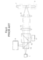
- Fig. 6 shows an example of such a two-light-source optical system. This configuration accommodates two different substrate thicknesses by using two light sources having different wavelengths.
- exit light from a first light source I is shaped by a collimator lens 13 and an objective lens 6, to form a minute spot on an optical disk 7 having a first substrate thickness.
- Reflection light from the optical disk is guided by a beam splitter 14 to a first detection system 3, which detects necessary information.
- an integrated module 17 incorporates a second light source whose wavelength is different from that of the first light source. Exit light from the integrated module 17 is superimposed on an optical path extending from the first light source by a wavelength combining element 10. In this case, a minute spot can be formed on a second optical disk 8 having a second substrate thickness different from that of the first optical disk. Reflection light from the optical disk is separated by the wavelength combining element 10, and a necessary signal is detected by a second detection system that is provided in the integrated module 17.
- the configuration shown in Figure 6 accommodates optical disks having different substrate thicknesses by employing two light sources having different wavelengths and establishing different objective lens incident states.
- the optical head shown in Fig. 6 is larger than the conventional single-light source optical head because the number of parts required is much greater than that of the conventional single-light source optical head. As a result, such a larger structure is more difficult to move, and hence high-speed access of the entire optical disk with a two-light-source optical head, is difficult to achieve.
- a separation-type optical head is conventionally used.
- a conventional separation-type optical head has a structure in which the optical system is divided at a position between the objective lens and a collimator lens, so that typically only the objective lens is moved in the optical axis direction.
- the separation-type optical head takes into account that a variation in distance between the collimated light portion and the objective lens does not affect the optical characteristics of the head.
- a separation-type optical head cannot be used with the head shown in Figure 6, because the second light source is not collimated. That is, since exit light from the second light source (which is indicated by broken lines) incorporated into module 17, is not collimated between the collimating lens 13 and the objective lens 6, the optical characteristics of the second light would be changed by a variation in the distance, which would prevent a minute spot from being formed on the second optical disk. Thus, the reproduced or recorded signal from/on the optical disk would deteriorate.
- an object of the present invention is to provide a structure for a two-wavelength separation-type optical head in which collimated light beams from two light sources having different wavelengths, form through a single objective lens minute, focused spots on optical disks having different thicknesses.
- an optical head in a first aspect of the present invention, includes a fixed optical system that includes a first light source outputting a first collimated light having a first wavelength, a first detection system for receiving a reflection of the first collimated light from a first optical. disk having a first substrate thickness, a second light source outputting a second collimated light parallel to the first collimated light and having a second wavelength different than that of the first wavelength, and a second detection system for receiving a reflection of the second collimated light from a second optical disk having a second substrate thickness different than that of the first substrate thickness.
- a movable optical system having an objective lens for focusing the first light on the first optical disk and for focusing a second light on the second optical disk, and an optical system is provided for converting a wave of the second collimated light and transmitting the second collimated light to the objective lens.
- the first collimated light and the second collimated light travel between the fixed optical system and the movable optical system.
- a driving system moves the movable optical system in a direction parallel to the first collimated light and the second collimated light.
- the movable optical system further includes a wavelength combining element for combining the first collimated light and the second collimated light and outputting a combined light to the objective lens.
- the first collimated light and the second collimated light are output from the fixed optical system at different positions.
- an optical head in a second aspect of the invention, includes a fixed optical system including a first light source for outputting a first collimated light having a first wavelength, a first detection system for receiving a reflection of the first collimated light from a first optical disk having a first substrate thickness, a second light source for outputting a second collimated light having a second wavelength different than that of the first wavelength, a second detection system for receiving a reflection of the second collimated light from a second optical disk having a second substrate thickness different than that of the first substrate thickness, and a wavelength-combining element for combining the first collimated light and the second collimated light.
- a movable optical system includes a wavelength-selective wavefront conversion element for converting a wavefront of the second collimated light and transmitting a second light, and an objective lens for focusing the first collimated light on the first optical disk and for focusing the second light, received from the wavelength-selective wavefront conversion element, on the second optical disk.
- an optical head in a third aspect of the invention, includes a fixed optical system including a first light source for outputting a first light having a first wavelength, a second light source for outputting a second light having a second wavelength different than that of the first wavelength, a wavelength-combining element for combining the first light and the second light, a collimator lens for collimating the first light and the second light from the wavelength-combining element, to produce first collimated light and second collimated light, a first detection system for receiving a reflection of the first collimated light from a first optical disk having a first substrate thickness, a second detection system for receiving a reflection of the second collimated light from a second optical disk having a second substrate thickness different than that of the first substrate thickness.
- a movable optical system includes a wavelength-selective wavefront conversion element for converting a wavefront of the second collimated light and transmitting a second light, and an objective lens for focusing the first collimated light on the first optical disk and for focusing the second light, received from the wavelength-selective wavefront conversion element, on the second optical disk.
- an optical head including a fixed optical system including a first light source for outputting a first light having a first wavelength, a second light source for outputting a second light having a second wavelength different than that of the first wavelength, a wavelength-combining element for combining the first light and the second light; and a collimator lens for collimating the first light and the second light, to produce first collimated light and second collimated light, respectively, and a shared detection system for receiving a reflection of the first collimated light from a first optical disk having a first substrate thickness, and for receiving a reflection of the second collimated light from a second optical disk having a second substrate thickness different than that of the first substrate thickness.
- a movable optical system of this embodiment of the present invention includes a wavelength-selective wavefront conversion element for converting a wavefront of the second collimated light and transmitting a second light, and an objective lens for focusing the first collimated light on said first optical disk and for focusing the second light, received from the wavelength-selective wavefront conversion element, on the second optical disk.
- an optical head in a fifth aspect of the present invention, includes a fixed optical system and a movable optical system.
- the fixed optical system includes a first light source for outputting a first light having a first wavelength, to be collimated to produce a first collimated light, and a first detection system for receiving a reflection of the first collimated light from a first optical disk having a first substrate thickness.
- the movable optical system includes a second light source for outputting a second, non-collimated light and having a second wavelength different than that of the first wavelength, an objective lens for focusing the first collimated light on the first optical disk and for focusing the second non-collimated light on the second optical disk, and a second detection system for receiving a reflection of the second non-collimated light from a second optical disk having a second substrate thickness different than that of the first substrate thickness.
- the second light source and the second detection system are preferably provided in a single module to reduce the size of the movable optical system.
- an optical head for transferring data to and from different optical disks and for compensating for different substrate thicknesses of the different optical disks.
- the optical head includes a fixed optical system for outputting a first light and a second light, wherein the first light includes a collimated light and the second light includes a collimated light and has a wavelength different from that of the first light.
- a movable optical system is provided for receiving the first light and the second light and including a mechanism for focusing the first light on an optical disk having a first thickness, and for focusing the second light on an optical disk having a second thickness different than that of the first thickness.
- a separation-type optical head is optimally used, such that both light sources are collimated.
- the optical characteristics of the light including the second light
- a minute spot can be formed on the second optical disk.
- distance (substrate thickness differences) variations in the present invention are irrelevant to its operation, since the invention utilizes collimated light, not non-collimated light as in the conventional systems.
- such can be achieved by a relatively small and easily movable, high-speed access optical head system.
- FIG. 1 which shows a first embodiment of the present invention
- light from a first light source 1 is converted into collimated light by a collimator lens 13, reflected by a wavelength combining device 10, and then shaped by an objective lens 6, to form a minute spot on a first optical disk 7.
- Reflection light from the first optical disk 7 travels along the same optical path in the opposite direction, and is separated by a beam splitter 14, so as to be guided to a first detection system 3.
- the first detection system 3 detects a focusing error signal, a tracking error signal, an information signal, and other signals, as is known in the optical disk art.
- DVD digital video disk
- CD-ROM compact disk-read-only memory
- a second optical disk 8 having a different substrate thickness than that of the first optical disk 7 is used instead of the first optical disk 7, the light from a second light source 2 is converted into collimated light by a collimator lens 13, reflected by a mirror 12, and then input to a wavefront conversion element 11 (preferably comprising a holographic optical element having a concentric holograni pattern or the like) which converts the wave surface of the collimated light so that it is properly focused by the objective lens 6 to form a minute spot on the second optical disk's 8 substrate.
- a wavefront conversion element 11 preferably comprising a holographic optical element having a concentric holograni pattern or the like
- the two collimated beams of light output from the collimating lenses 13 are parallel to one another.
- the resulting light is passed through the wavelength combining element 10, and shaped by the objective lens 6, to form a minute spot on a second optical disk 8.
- Reflection light from the second optical disk 8 travels along the same optical path in the opposite direction, and is separated by a beam splitter 14 so as to be guided to a second detection system 4.
- the second detection system 4 similarly detects a focusing error signal, a tracking error signal, an information signal, and other signals.
- the wavelength combining device 10 is a conventional device well known to those ordinarily skilled in this art field and, for example, could be a beam splitter, wavelength filter or the like having a multilayered interference film.
- the wavelength combining device 10 operates similarly to a beam splitter, such that some light is passed and other light is reflected.
- a glass lens or a hologram element can be used as the wavefront conversion element 11.
- the beam splitters 14 are also well known elements to those ordinarily skilled in this art field and could include, for example, a polarizing beam splitter combined with a quarter-wave plate.
- the light sources 1, 2, the detection systems 4, 5, the collimator lenses 13, and the beam splitters 14 are provided in a fixed optical system 5, whereas the objective lens 6, the wavelength combining element 10, the mirror 12, and the wavefront conversion element 11 are provided in a movable optical system 9.
- the movable optical system 9 is movable only along the optical axis direction of collimated light beams, or the radial direction of the optical disks 7 and 8.
- a conventional drive mechanism (not illustrated) including a voice coil motor or a screw can be used, for example, as a moving mechanism to move the movable optical system 9.
- each of the light beams is a collimated light beam which permits the movable optical system to be moved freely without affecting the optical characteristics of the optical head.
- the first embodiment of the present invention takes into account that only non-collimated light is affected by distance, and that distance does not vary the optical characteristics of collimated light. As a result, the optical characteristics of the signals do not deteriorate and substrates having different thicknesses can be accommodated.
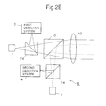
- FIG. 2A a second embodiment of the invention is illustrated. in which the fixed optical system is simplified by positioning the wavelength-combining element 10 between the beam splitters 14 and a movable optical system 9.
- the light from a first light source 1 is converted into collimated light by a collimator lens 13, passed through a wavelength-combining element 10, reflected by a mirror 12, passed through a wavelength-selective wavefront conversion element 15, and then shaped by an objective lens 6, to form a minute spot on a first optical disk 7.
- Reflection light from the first optical disk 7 travels along the same optical path in the opposite direction, and is separated by a beam splitter 14, so as to be guided to a first detection system 3.
- the first detection system 3 detects a focusing error signal, a tracking error signal, an information signal, and other signals, as mentioned above.
- the light from a second light source 2 is converted into collimated light by a collimator lens 13, superimposed on the optical path extending from the first light source by the wavelength-combining device 10, reflected by the mirror 12, and then input to the wavelength-selective wavefront conversion element 15 which operates as described above to accommodate for the different substrate thickness of the second optical disk 8.
- the resulting light is shaped by the objective lens 6, to form a minute spot on the second optical disk 8.
- the movable optical system 9 has only three components (e.g., elements 12, 15, and 6), and thus is lighter than that of the first embodiment.
- Reflection light from the second optical disk 8 travels along the same optical path in the opposite direction, and is separated by a beam splitter 14, so as to be guided to a second detection system 4.
- the number of collimator lenses in the fixed optical system 5 could be reduced to one by positioning the wavelength combining device 10 between the collimator lens 13 and the beam splitters 14, as shown in Figure 2B.
- the wavelength combining device 10 between the collimator lens 13 and the beam splitters 14, as shown in Figure 2B.
- an integrated module (discussed in detail below with respect to Figure 5) could be used in which the light source and the detection optical system are integrated to further reduce the number of parts and the corresponding size and weight of the optical head.
- the wavelength-selective wavefront conversion element 15 has no effect on the wavelength of the first light source 1, and converts only the wave surface of the wavelength of the second light source 2.
- a relief hologram element can be used as such a wavefront conversion element.
- h is the lattice height of the hologram element
- n is the refractive index of the element
- ⁇ 1 and ⁇ 2 are wavelengths of the first and second light sources, respectively.
- the objective lens 6, the wavelength-selective wavefront conversion element 15, and the mirror 12 are provided in the movable optical system 9, and the remaining parts are provided in the fixed optical system 5.
- This structure allows the movable optical system to be made smaller when compared to the first embodiment, because the wavelength combining element 10 is moved to the fixed optical system 5. As discussed above, a smaller movable system 9 moves faster and provides the optical head with quicker response characteristics.
- FIG. 3 a third embodiment of the invention is illustrated.
- the fixed optical system is simplified by positioning the wavelength-combining element 10 between the beam splitter 14 and the first and second light sources, 1, 2, respectively, as shown in Figure 3. This results in a more compact and lightweight system.
- the third embodiment is further different than the second embodiment in that the third embodiment uses a shared detection system 16, instead of first and second detection systems.
- This structure further results in a more compact and lightweight system having a higher access speed.
- the operation of the shared detection system 16 is the same as the first detection 3 of Figure 1 (as well as that of the embodiment of Figure 5 discussed briefly below).
- One detection system such as the first detection system may be used for the first and second light because the first and second optical disks are not used simultaneously (e.g., only one disk is usable at a time). Namely, the first light is off when the second light is on and vice versa.
- Figures 2A (and 2B) and 3 are preferable since the fewest number of elements are included in the movable system, and therefore these embodiments are the lightest, making access speed the quickest.
- the modified second embodiment of Figure 2B is light since it uses the same movable optical system as that of Figure 2A, and it also has the added advantage of having a relatively smaller fixed optical system since only one collimator lens is employed in the fixed optical system.
- Figure 4 discussed below forms the heaviest of the movable systems.
- a fourth embodiment of the invention is shown in Figure 4.
- the second light source 17 and the wavelength-combining element 10 are positioned in the movable optical system 9, as opposed to both first and second light sources and the wavelength-combining element 10 being in the fixed optical system, as in the second and third embodiments described above.
- the fixed optical system 5 and the movable optical system 9 are related to each other only by the collimated light from the first light source 1.
- an integrated module 17 is used in which the light source is integral with the detection system (e.g., see the discussion below regarding the integrated module below of Figure 5).
- This configuration is advantageous in that the collimator lens and the wavefront-conversion element can be omitted by properly setting the distance between the light source and the objective lens.
- This configuration eliminates the need for a collimator lens 13, in that the second light is shaped by the objective lens 6 to form a minute spot on the recording layer of the second disk 8 by setting the distance between the second light source and the objective lens 6. Therefore, a collimator lens for the second light is unnecessary.
- the integrated module 17 includes a light source 19 and a photodetector 20.
- the light from the light source 19 is directly output from the integrated module 17.
- a hologram element 18 directs the incoming light signal to the photodetector 20. As mentioned above, the hologram element 18 will affect only the incoming light, but will not affect the outgoing light from the light source.
- a two-wavelength separation type optical head which accommodates optical disks having different substrate thicknesses and utilizes a fixed optical system and a movable optical system to make the movable parts of the head lighter and to increase the operating speed of the optical head.
Landscapes
- Physics & Mathematics (AREA)
- Optics & Photonics (AREA)
- Optical Head (AREA)
- Moving Of The Head For Recording And Reproducing By Optical Means (AREA)
Abstract
Description
Having thus described my invention, what I claim as new and desire to secure by Letters Patent is as follows:
Claims (30)
- An optical head, comprising:a fixed optical system including:a first light source for outputting a first collimated light having a first wavelength;a first detection system for receiving a reflection of said first collimated light from a first optical disk having a first substrate thickness;a second light source for outputting a second collimated light having a second wavelength different than that of said first wavelength; anda second detection system for receiving a reflection of said second collimated light from a second optical disk having a second substrate thickness different than that of said first substrate thickness; anda movable optical system including:an objective lens for focusing said first collimated light on said first optical disk, and for focusing said second collimated light on said second optical disk; andan optical system for converting a wavefront of said second collimated light, and transmitting said second collimated light to said objective lens.
- The optical head as in claim 1, wherein said movable optical system further comprises a wavelength-combining element for combining said first collimated light and said second light, and for outputting a combined light to said objective lens,said first collimated light and said second collimated light being output from said fixed optical system at different positions.
- The optical head as in claim 2, further comprising:a driving system for moving said movable optical system in a direction parallel to said first collimated light and said second collimated light, said second collimated light being parallel to said first collimated light,wherein said first collimated light and said second collimated light travel between said fixed optical system and said movable optical system.
- An optical head comprising:a fixed optical system including:a first light source for outputting a first collimated light having a first wavelength;a first detection system for receiving a reflection of said first collimated light from a first optical disk having a first substrate thickness;a second light source for outputting a second collimated light having a second wavelength different than that of said first wavelength;a second detection system for receiving a reflection of said second collimated light from a second optical disk having a second substrate thickness different than that of said first substrate thickness; anda wavelength-combining element for combining said first collimated light and said second collimated light; anda movable optical system comprising:a wavelength-selective wavefront conversion element for converting a wavefront of said second collimated light and transmitting a second light; andan objective lens for focusing said first collimated light on said first optical disk and for focusing said second light, received from said wavelength-selective wavefront conversion element, on said second optical disk.
- The optical head as in claim 4, further comprising:a driving system for moving said movable optical system in a direction parallel to one of said first collimated light and said second collimated light,wherein said first collimated light and said second collimated light travel between said fixed optical system and said movable optical system.
- The optical head as in claim 4, wherein said fixed optical system includes a first collimator lens positioned between said first detection system and said wavelength-combining element, and a second collimator lens positioned between said second detection system and said wavelength-combining element.
- An optical head comprising:a fixed optical system including:a first light source for outputting a first light having a first wavelength;a second light source for outputting a second light having a second wavelength different than that of said first wavelength;a wavelength-combining element for combining said first light and said second light;a collimator lens for collimating said first light and said second light from said wavelength-combining element, to produce first collimated light and second collimated light;a first detection system for receiving a reflection of said first collimated light from a first optical disk having a first substrate thickness;a second detection system for receiving a reflection of said second collimated light from a second optical disk having a second substrate thickness different than that of said first substrate thickness; anda movable optical system comprising:a wavelength-selective wavefront conversion element for converting a wavefront of said second collimated light and transmitting a second light; andan objective lens for focusing said first collimated light on said first optical disk and for focusing said second light, received from said wavelength-selective wavefront conversion element, on said second optical disk.
- The optical head as in claim 7, further comprising:a driving system for moving said movable optical system in a direction parallel to one of said first collimated light and said second collimated light,wherein said first collimated light and said second collimated light travel between said fixed optical system and said movable optical system.
- The optical head according to claim 7, wherein said fixed optical system further comprises a first beam splitter positioned between said first detection system and said wavelength-combining element, and a second beam splitter positioned between said second detection system and said wavelength-combining element.
- An optical head comprising:a fixed optical system including:a first light source for outputting a first light having a first wavelength;a second light source for outputting a second light having a second wavelength different than that of said first wavelength;a wavelength-combining element for combining said first light and said second light; anda collimator lens for collimating said first light and said second light, to produce first collimated light and second collimated light, respectively; anda shared detection system for receiving a reflection of said first collimated light from a first optical disk having a first substrate thickness, and for receiving a reflection of said second collimated light from a second optical disk having a second substrate thickness different than that of said first substrate thickness; anda movable optical system comprising:a wavelength-selective wavefront conversion element for converting a wavefront of said second collimated light and transmitting a second light; andan objective lens for focusing said first collimated light on said first optical disk and for focusing said second light, received from said wavelength-selective wavefront conversion element, on said second optical disk.
- The optical head as in claim 10, wherein said fixed optical system further comprises a beam splitter positioned between said said wavelength-combining element and said collimator lens, andwherein said wavelength-combining element receives said first light and said second light directly from said first light source and said second light source, respectively.
- The optical head as in claim 10, further comprising:a driving system for moving said movable optical system in a direction parallel to said first collimated light and said second collimated light, said second collimated light being parallel to said first collimated light,wherein said first collimated light and said second collimated light travel between said fixed optical system and said movable optical system.
- An optical head comprising:a fixed optical system including:a first light source for outputting a first light having a first wavelength, for collimation to produce a first collimated light; anda first detection system for receiving a reflection of said first collimated light from a first optical disk having a first substrate thickness; anda movable optical system including:a second light source for outputting a second, non-collimated light and having a second wavelength different than that of said first wavelength;an objective lens for focusing said first collimated light on said first optical disk and for focusing said second non-collimated light on said second optical disk; anda second detection system for receiving a reflection of said second non-collimated light from a second optical disk having a second substrate thickness different than that of said first substrate thickness.
- The optical head as in claim 13, wherein said fixed optical system further comprises a collimator lens for receiving said first light and for producing said first collimated light, andwherein said movable optical system further comprises:a wavelength-combining element for receiving said first collimated light from said collimator lens of said fixed optical system and for receiving said second non-collimated light from said second light source, and for providing an output to said objective lens.
- The optical head as in claim 14, further comprising:a driving system for moving said movable optical system in a direction parallel to said first collimated light,wherein said second light source is positioned at a predetermined distance from said objective lens such that said second light, without collimation, is shaped by said objective lens into a minute spot on said second optical disk.
- The optical head as in claim 13, wherein said second light source and said second detection system are integrated into a single module.
- An optical head for transferring data to and from different optical disks and for compensating for different substrate thicknesses of said different optical disks, comprising:a fixed optical system for outputting a first light and a second light, wherein said first light comprises a collimated light said second light comprises a collimated light and has a wavelength different from that of said first light; anda movable optical system for receiving said first light and said second light and including means for focusing said first light on an optical disk having a first thickness, and for focusing said second light on an optical disk having a second thickness different than that of said first thickness.
- The optical head as in claim 17, wherein said means for focusing comprises an objective lens, andwherein said first thickness corresponds to a thickness of a reflective surface of a first optical disk of said optical disks and said second thickness corresponds to a thickness of a reflective surface of a second optical disk of said optical disks.
- The optical head as in claim 18, wherein said fixed optical system includes a first detector for receiving said first light reflected from said reflective surface of said first optical disk, and a second detector for receiving said second light reflected from said reflective surface of said second optical disk.
- The optical head as in claim 17, wherein said movable optical system is movable in a direction parallel to said first light.
- The optical head as in claim 19, wherein said first detector includes a first light source for outputting said first light, and said second detector includes a second light source for outputting said second light.
- The optical head as in claim 17, wherein said first light and said second light are parallel.
- The optical head as in claim 17, wherein said first light and said second light have a common axis.
- The optical head as in claim 17, wherein said fixed optical system includes a wavelength-combining device for combining said first light and said second light.
- The optical head as in claim 17, wherein said movable optical system includes a wavelength-combining device for combining said first light and said second light.
- The optical head as in claim 18, wherein said movable optical system includes a wavefront-conversion element adjacent said objective lens for adjusting a wavefront of said second light.
- The optical head as in claim 19, wherein said first detector and said second detector comprise a single, shared detector.
- The optical head as in claim 21, wherein said first detector includes a hologram element for deflecting said first light reflected from said first surface and for not affecting said first light output from said first light source, andwherein said second detector includes said hologram element for deflecting said second light reflected from said second surface and for not affecting said second light output from said second light source.
- The optical head according to claim 24, wherein said fixed optical system includes a single collimator lens positioned to receive and collimate said first and second light from said wavelength-combining element, and for providing said first collimated light and said second collimated light to said movable optical system.
- The optical head according to claim 17, wherein said fixed optical system includes:a wavelength-combining element for receiving said first light and said second light;a single beam splitter for receiving an output from said wavelength-combining element;a single collimator lens, positioned to receive an output from said beam splitter, for providing an output to said movable optical system; anda single, shared detection system for receiving said first light and said second light reflected from a first optical disk and a second optical disk, respectively, of said different optical disks.
Applications Claiming Priority (3)
| Application Number | Priority Date | Filing Date | Title |
|---|---|---|---|
| JP251492/96 | 1996-09-24 | ||
| JP25149296 | 1996-09-24 | ||
| JP8251492A JPH10106019A (en) | 1996-09-24 | 1996-09-24 | Two-wavelength separation type optical head |
Publications (4)
| Publication Number | Publication Date |
|---|---|
| EP0831466A2 true EP0831466A2 (en) | 1998-03-25 |
| EP0831466A3 EP0831466A3 (en) | 1998-05-13 |
| EP0831466B1 EP0831466B1 (en) | 2002-04-10 |
| EP0831466B8 EP0831466B8 (en) | 2002-10-09 |
Family
ID=17223610
Family Applications (1)
| Application Number | Title | Priority Date | Filing Date |
|---|---|---|---|
| EP97402199A Expired - Lifetime EP0831466B8 (en) | 1996-09-24 | 1997-09-22 | Optical head having multiple light sources having different wavelengths |
Country Status (3)
| Country | Link |
|---|---|
| US (1) | US5982732A (en) |
| EP (1) | EP0831466B8 (en) |
| JP (1) | JPH10106019A (en) |
Cited By (10)
| Publication number | Priority date | Publication date | Assignee | Title |
|---|---|---|---|---|
| EP0881634A1 (en) * | 1997-05-29 | 1998-12-02 | Nec Corporation | Optical head device |
| RU2162253C1 (en) * | 2000-06-26 | 2001-01-20 | Закрытое акционерное общество "Инфокристал" | Method and device for automatic focusing on optical beam onto data medium effective layer |
| EP1117096A3 (en) * | 2000-01-14 | 2002-07-03 | Samsung Electronics Co., Ltd. | Optical pickup |
| RU2187153C2 (en) * | 2000-10-10 | 2002-08-10 | Общество С Ограниченной Ответственностью "Инсмат Технология" | Method and disk-type data medium for tracking data track of disk-type optical- record medium |
| EP1096483A3 (en) * | 1999-10-30 | 2003-04-23 | Samsung Electronics Co., Ltd. | Optical pickup |
| EP1422696A3 (en) * | 2002-11-25 | 2005-01-19 | Matsushita Electric Industrial Co., Ltd. | Optical head apparatus |
| EP1630799A1 (en) * | 2004-08-27 | 2006-03-01 | Mitsumi Electric Co., Ltd. | Light-emission and reception module for optical pickup and optical pickup |
| US7245407B2 (en) | 2002-06-10 | 2007-07-17 | Matsushita Electric Industrial Co., Ltd. | Complex objective lens compatible with information media of different thicknesses |
| CN100350479C (en) * | 2004-04-28 | 2007-11-21 | 索尼株式会社 | Optical pickup and recording and/or reproducing apparatus for optical recording medium |
| US7443778B2 (en) | 2003-02-27 | 2008-10-28 | Matsushita Electric Industrial Co., Ltd. | Optical head device and optical information device using the same, computer, optical disk player, car navigation system, optical disk recorder, and optical disk server |
Families Citing this family (14)
| Publication number | Priority date | Publication date | Assignee | Title |
|---|---|---|---|---|
| US6304540B1 (en) * | 1998-03-30 | 2001-10-16 | Samsung Electronics Co., Ltd. | Optical pickup compatible with a digital versatile disk and a recordable compact disk using a holographic ring lens |
| JP3304053B2 (en) * | 1997-05-30 | 2002-07-22 | 松下電器産業株式会社 | Optical head and optical disk device |
| US20010050892A1 (en) * | 1997-07-11 | 2001-12-13 | Yoshitaka Takahashi | Optical disk apparatus compatible with different types of mediums |
| KR100291557B1 (en) * | 1997-08-30 | 2001-06-01 | 윤종용 | Optical pickup compatible with cd-r and dvd using round shield surface |
| US6377536B1 (en) * | 1997-12-22 | 2002-04-23 | Lg Electronics Inc. | Optical pick-up apparatus |
| JP3638210B2 (en) * | 1998-06-15 | 2005-04-13 | シャープ株式会社 | Hologram laser unit and optical pickup device using the same |
| JP2000311379A (en) * | 1999-04-23 | 2000-11-07 | Asahi Optical Co Ltd | Optical disk drive |
| US6760296B1 (en) * | 1999-06-24 | 2004-07-06 | Sony Corporation | Optical integrated device, optical pickup and optical disk apparatus |
| TW563120B (en) * | 1999-10-26 | 2003-11-21 | Toshiba Corp | Optical head and optical disk apparatus having the same |
| JP2002025096A (en) * | 2000-07-07 | 2002-01-25 | Matsushita Electric Ind Co Ltd | Semiconductor light source, optical pickup head device, and information recording / reproducing device |
| KR20030093683A (en) * | 2002-06-05 | 2003-12-11 | 삼성전자주식회사 | Compatible optical pickup |
| US7158454B2 (en) * | 2003-12-17 | 2007-01-02 | Acute Applied Technologies Inc. | Optical device |
| US8177394B2 (en) * | 2008-11-07 | 2012-05-15 | Endure Medical, Inc. | Stereoscopic illumination system for microscope |
| KR20220030067A (en) * | 2020-09-02 | 2022-03-10 | 삼성전자주식회사 | Wafer inspection apparatus and system including same |
Family Cites Families (13)
| Publication number | Priority date | Publication date | Assignee | Title |
|---|---|---|---|---|
| JPS62257641A (en) * | 1986-04-30 | 1987-11-10 | Toshiba Corp | Optical head |
| US5148421A (en) * | 1990-04-20 | 1992-09-15 | Matsushita Electric Industrial Co., Ltd. | Optical head |
| JP3136758B2 (en) * | 1991-05-10 | 2001-02-19 | 株式会社日立製作所 | Optical information recording / reproducing device |
| KR100246212B1 (en) * | 1991-05-31 | 2000-03-15 | 이데이 노부유끼 | Optical disk device |
| US5619488A (en) * | 1991-09-07 | 1997-04-08 | Fuji Xerox Co., Ltd. | Information recording device |
| JPH05210868A (en) * | 1992-01-30 | 1993-08-20 | Hitachi Ltd | Multibeam separation type optical head |
| JPH06325405A (en) * | 1992-09-11 | 1994-11-25 | Toshiba Corp | Optical recording and reproducing device |
| JP3309470B2 (en) * | 1993-03-10 | 2002-07-29 | 松下電器産業株式会社 | Optical information recording / reproducing device |
| JP3240846B2 (en) * | 1994-08-12 | 2001-12-25 | 松下電器産業株式会社 | Light head |
| JPH08221798A (en) * | 1995-02-13 | 1996-08-30 | Hitachi Ltd | Separate type multi-beam optical head |
| US5526338A (en) * | 1995-03-10 | 1996-06-11 | Yeda Research & Development Co. Ltd. | Method and apparatus for storage and retrieval with multilayer optical disks |
| DE69627752T2 (en) * | 1995-06-05 | 2003-10-16 | Nec Corp., Tokio/Tokyo | Optical playback head device for various disc types |
| JP3062099B2 (en) * | 1996-02-06 | 2000-07-10 | 日本電気株式会社 | Optical head device |
-
1996
- 1996-09-24 JP JP8251492A patent/JPH10106019A/en active Pending
-
1997
- 1997-09-12 US US08/928,393 patent/US5982732A/en not_active Expired - Fee Related
- 1997-09-22 EP EP97402199A patent/EP0831466B8/en not_active Expired - Lifetime
Cited By (21)
| Publication number | Priority date | Publication date | Assignee | Title |
|---|---|---|---|---|
| US6201780B1 (en) | 1997-05-29 | 2001-03-13 | Nec Corporation | Optical head with a phase plate for different types of disks |
| EP0881634A1 (en) * | 1997-05-29 | 1998-12-02 | Nec Corporation | Optical head device |
| US7120109B1 (en) | 1999-10-30 | 2006-10-10 | Samsung Electronics Co., Ltd. | Optical pickup with improved collimating lens for use with long and short wavelength laser beams |
| EP1096483A3 (en) * | 1999-10-30 | 2003-04-23 | Samsung Electronics Co., Ltd. | Optical pickup |
| EP1117096A3 (en) * | 2000-01-14 | 2002-07-03 | Samsung Electronics Co., Ltd. | Optical pickup |
| US6590851B1 (en) | 2000-01-14 | 2003-07-08 | Samsung Electronics Co., Ltd. | Optical pickup for recording/reproducing optical discs of multiple thicknesses |
| RU2162253C1 (en) * | 2000-06-26 | 2001-01-20 | Закрытое акционерное общество "Инфокристал" | Method and device for automatic focusing on optical beam onto data medium effective layer |
| RU2187153C2 (en) * | 2000-10-10 | 2002-08-10 | Общество С Ограниченной Ответственностью "Инсмат Технология" | Method and disk-type data medium for tracking data track of disk-type optical- record medium |
| US7245407B2 (en) | 2002-06-10 | 2007-07-17 | Matsushita Electric Industrial Co., Ltd. | Complex objective lens compatible with information media of different thicknesses |
| US7330292B2 (en) | 2002-06-10 | 2008-02-12 | Matsushita Electric Industrial Co., Ltd. | Complex objective lens, optical head, optical information apparatus, computer, optical disk player, car navigation system, optical disk recorder, and optical disk server |
| US7433290B2 (en) | 2002-06-10 | 2008-10-07 | Matsushita Electric Industrial Co., Ltd. | Complex objective lens, optical head, optical information apparatus, computer, optical disk player, car navigation system, optical disk recorder, and optical disk server |
| US7911923B2 (en) | 2002-06-10 | 2011-03-22 | Panasonic Corporation | Complex objective lens, optical head, optical information apparatus, computer, optical disk player, car navigation system, optical disk recorder, and optical disk server |
| US7920310B2 (en) | 2002-06-10 | 2011-04-05 | Panasonic Corporation | Complex objective lens for an optical head and optical information apparatus |
| US8325582B2 (en) | 2002-06-10 | 2012-12-04 | Panasonic Corporation | Complex objective lens, optical head, optical information apparatus, computer, optical disk player, car navigation system, optical disk recorder, and optical disk server |
| EP1422696A3 (en) * | 2002-11-25 | 2005-01-19 | Matsushita Electric Industrial Co., Ltd. | Optical head apparatus |
| US7248409B2 (en) | 2002-11-25 | 2007-07-24 | Matsushita Electric Industrial Co., Ltd. | Optical element, optical lens, optical head apparatus, optical information apparatus, computer, optical information medium player, car navigation system, optical information medium recorder, and optical information medium server |
| CN100337278C (en) * | 2002-11-25 | 2007-09-12 | 松下电器产业株式会社 | Optical element, lens, optical head, optical information device and system using same |
| US7443778B2 (en) | 2003-02-27 | 2008-10-28 | Matsushita Electric Industrial Co., Ltd. | Optical head device and optical information device using the same, computer, optical disk player, car navigation system, optical disk recorder, and optical disk server |
| US8509047B2 (en) | 2003-02-27 | 2013-08-13 | Panasonic Corporation | Optical head device and optical information device using the same, computer, optical disk player, car navigation system, optical disk recorder, and optical disk server |
| CN100350479C (en) * | 2004-04-28 | 2007-11-21 | 索尼株式会社 | Optical pickup and recording and/or reproducing apparatus for optical recording medium |
| EP1630799A1 (en) * | 2004-08-27 | 2006-03-01 | Mitsumi Electric Co., Ltd. | Light-emission and reception module for optical pickup and optical pickup |
Also Published As
| Publication number | Publication date |
|---|---|
| EP0831466A3 (en) | 1998-05-13 |
| EP0831466B1 (en) | 2002-04-10 |
| US5982732A (en) | 1999-11-09 |
| JPH10106019A (en) | 1998-04-24 |
| EP0831466B8 (en) | 2002-10-09 |
Similar Documents
| Publication | Publication Date | Title |
|---|---|---|
| US5982732A (en) | Optical head having multiple light sources having different wavelengths | |
| US6043912A (en) | Optical pickup compatible with a digital versatile disk and a recordable compact disk using a holographic ring lens | |
| KR100266223B1 (en) | Optical pickup apparatus | |
| US5737294A (en) | Objective lens with two numerical apertures for reading/writing two optical discs | |
| KR19990047850A (en) | Optical pickup with objectives compatible with multiple optical discs | |
| US6304540B1 (en) | Optical pickup compatible with a digital versatile disk and a recordable compact disk using a holographic ring lens | |
| EP1156483B1 (en) | Compatible optical disk player and data recording and reproducing method | |
| US6240053B1 (en) | Optical pickup device | |
| EP1688937B1 (en) | Optical pickup apparatus which is compatible with multiple types of media | |
| KR19990074653A (en) | Optical pickup using optically adjustable iris | |
| KR100263154B1 (en) | Optical pick-up using optical phase plate | |
| KR100255243B1 (en) | Optical pickup compatible with optical recording media | |
| US6304542B1 (en) | Compact dual wavelength optical pickup head | |
| US7760612B2 (en) | Optical element and optical head device using it, and optical information device using this optical head device, and computer, optical disk player, car navigation system, optical disk recorder and optical disk server using this optical information device | |
| KR100228678B1 (en) | Optical pickup using polarized beam splitter | |
| KR100209917B1 (en) | Actuator Separate Optical Pickup | |
| US6069862A (en) | Compact optical head including two light emitters having parallel optical axes | |
| US5379286A (en) | Optical information recording-reproducing apparatus having a prism | |
| JP3896171B2 (en) | Optical pickup and optical disk apparatus | |
| KR20040076328A (en) | Optical pickup apparatus comprising optical device with phase shift coating layer | |
| JPH1027373A (en) | Optical head and optical disk device | |
| KR100459154B1 (en) | Optical pickup device for different optical discs | |
| KR100468962B1 (en) | Optical pickup | |
| JPH06168462A (en) | Optical head | |
| KR100238069B1 (en) | Optical pickup compatible with cd-r and dvd using hologram |
Legal Events
| Date | Code | Title | Description |
|---|---|---|---|
| PUAI | Public reference made under article 153(3) epc to a published international application that has entered the european phase |
Free format text: ORIGINAL CODE: 0009012 |
|
| AK | Designated contracting states |
Kind code of ref document: A2 Designated state(s): NL |
|
| AX | Request for extension of the european patent |
Free format text: AL;LT;LV;RO;SI |
|
| PUAL | Search report despatched |
Free format text: ORIGINAL CODE: 0009013 |
|
| RHK1 | Main classification (correction) |
Ipc: G11B 7/00 |
|
| AK | Designated contracting states |
Kind code of ref document: A3 Designated state(s): AT BE CH DE DK ES FI FR GB GR IE IT LI LU MC NL PT SE |
|
| AX | Request for extension of the european patent |
Free format text: AL;LT;LV;RO;SI |
|
| 17P | Request for examination filed |
Effective date: 19981026 |
|
| 17Q | First examination report despatched |
Effective date: 19981124 |
|
| AKX | Designation fees paid |
Free format text: DE NL |
|
| RBV | Designated contracting states (corrected) |
Designated state(s): DE NL |
|
| GRAG | Despatch of communication of intention to grant |
Free format text: ORIGINAL CODE: EPIDOS AGRA |
|
| GRAG | Despatch of communication of intention to grant |
Free format text: ORIGINAL CODE: EPIDOS AGRA |
|
| GRAH | Despatch of communication of intention to grant a patent |
Free format text: ORIGINAL CODE: EPIDOS IGRA |
|
| RBV | Designated contracting states (corrected) |
Designated state(s): NL |
|
| GRAH | Despatch of communication of intention to grant a patent |
Free format text: ORIGINAL CODE: EPIDOS IGRA |
|
| REG | Reference to a national code |
Ref country code: DE Ref legal event code: 8566 |
|
| GRAA | (expected) grant |
Free format text: ORIGINAL CODE: 0009210 |
|
| AK | Designated contracting states |
Kind code of ref document: B1 Designated state(s): NL |
|
| PLBE | No opposition filed within time limit |
Free format text: ORIGINAL CODE: 0009261 |
|
| STAA | Information on the status of an ep patent application or granted ep patent |
Free format text: STATUS: NO OPPOSITION FILED WITHIN TIME LIMIT |
|
| 26N | No opposition filed |
Effective date: 20030113 |
|
| PGFP | Annual fee paid to national office [announced via postgrant information from national office to epo] |
Ref country code: NL Payment date: 20030922 Year of fee payment: 7 |
|
| ET | Fr: translation filed | ||
| PGFP | Annual fee paid to national office [announced via postgrant information from national office to epo] |
Ref country code: FR Payment date: 20040213 Year of fee payment: 7 |
|
| PG25 | Lapsed in a contracting state [announced via postgrant information from national office to epo] |
Ref country code: NL Free format text: LAPSE BECAUSE OF NON-PAYMENT OF DUE FEES Effective date: 20050401 |
|
| PG25 | Lapsed in a contracting state [announced via postgrant information from national office to epo] |
Ref country code: FR Free format text: LAPSE BECAUSE OF NON-PAYMENT OF DUE FEES Effective date: 20050531 |
|
| NLV4 | Nl: lapsed or anulled due to non-payment of the annual fee |
Effective date: 20050401 |
|
| REG | Reference to a national code |
Ref country code: FR Ref legal event code: ST |