EP0831486A2 - Appareil d'enregistrement/de reproduction d'informations et méthode - Google Patents
Appareil d'enregistrement/de reproduction d'informations et méthode Download PDFInfo
- Publication number
- EP0831486A2 EP0831486A2 EP97402200A EP97402200A EP0831486A2 EP 0831486 A2 EP0831486 A2 EP 0831486A2 EP 97402200 A EP97402200 A EP 97402200A EP 97402200 A EP97402200 A EP 97402200A EP 0831486 A2 EP0831486 A2 EP 0831486A2
- Authority
- EP
- European Patent Office
- Prior art keywords
- recording
- data
- error correction
- audio
- information signal
- Prior art date
- Legal status (The legal status is an assumption and is not a legal conclusion. Google has not performed a legal analysis and makes no representation as to the accuracy of the status listed.)
- Withdrawn
Links
- 238000000034 method Methods 0.000 title claims description 14
- 230000005236 sound signal Effects 0.000 description 38
- 238000010586 diagram Methods 0.000 description 8
- 238000010276 construction Methods 0.000 description 6
- 238000005070 sampling Methods 0.000 description 6
- 230000008569 process Effects 0.000 description 5
- 230000003247 decreasing effect Effects 0.000 description 3
- 230000002159 abnormal effect Effects 0.000 description 2
- 238000006243 chemical reaction Methods 0.000 description 2
- 238000011109 contamination Methods 0.000 description 2
- 230000000593 degrading effect Effects 0.000 description 2
- 230000008901 benefit Effects 0.000 description 1
- 230000015556 catabolic process Effects 0.000 description 1
- 238000006731 degradation reaction Methods 0.000 description 1
- 230000003111 delayed effect Effects 0.000 description 1
- 230000006866 deterioration Effects 0.000 description 1
- 230000006872 improvement Effects 0.000 description 1
- 238000007689 inspection Methods 0.000 description 1
- 230000007257 malfunction Effects 0.000 description 1
- 238000012986 modification Methods 0.000 description 1
- 230000004048 modification Effects 0.000 description 1
- 230000002265 prevention Effects 0.000 description 1
- 230000002250 progressing effect Effects 0.000 description 1
- 238000013139 quantization Methods 0.000 description 1
- 230000008707 rearrangement Effects 0.000 description 1
Images


Classifications
-
- G—PHYSICS
- G11—INFORMATION STORAGE
- G11B—INFORMATION STORAGE BASED ON RELATIVE MOVEMENT BETWEEN RECORD CARRIER AND TRANSDUCER
- G11B20/00—Signal processing not specific to the method of recording or reproducing; Circuits therefor
- G11B20/10—Digital recording or reproducing
- G11B20/18—Error detection or correction; Testing, e.g. of drop-outs
- G11B20/1806—Pulse code modulation systems for audio signals
- G11B20/1813—Pulse code modulation systems for audio signals by adding special bits or symbols to the coded information
-
- G—PHYSICS
- G11—INFORMATION STORAGE
- G11B—INFORMATION STORAGE BASED ON RELATIVE MOVEMENT BETWEEN RECORD CARRIER AND TRANSDUCER
- G11B19/00—Driving, starting, stopping record carriers not specifically of filamentary or web form, or of supports therefor; Control thereof; Control of operating function ; Driving both disc and head
- G11B19/02—Control of operating function, e.g. switching from recording to reproducing
- G11B19/04—Arrangements for preventing, inhibiting, or warning against double recording on the same blank or against other recording or reproducing malfunctions
-
- G—PHYSICS
- G11—INFORMATION STORAGE
- G11B—INFORMATION STORAGE BASED ON RELATIVE MOVEMENT BETWEEN RECORD CARRIER AND TRANSDUCER
- G11B27/00—Editing; Indexing; Addressing; Timing or synchronising; Monitoring; Measuring tape travel
- G11B27/02—Editing, e.g. varying the order of information signals recorded on, or reproduced from, record carriers
- G11B27/031—Electronic editing of digitised analogue information signals, e.g. audio or video signals
- G11B27/036—Insert-editing
-
- G—PHYSICS
- G11—INFORMATION STORAGE
- G11B—INFORMATION STORAGE BASED ON RELATIVE MOVEMENT BETWEEN RECORD CARRIER AND TRANSDUCER
- G11B5/00—Recording by magnetisation or demagnetisation of a record carrier; Reproducing by magnetic means; Record carriers therefor
- G11B5/008—Recording on, or reproducing or erasing from, magnetic tapes, sheets, e.g. cards, or wires
- G11B5/00813—Recording on, or reproducing or erasing from, magnetic tapes, sheets, e.g. cards, or wires magnetic tapes
- G11B5/00847—Recording on, or reproducing or erasing from, magnetic tapes, sheets, e.g. cards, or wires magnetic tapes on transverse tracks
- G11B5/0086—Recording on, or reproducing or erasing from, magnetic tapes, sheets, e.g. cards, or wires magnetic tapes on transverse tracks using cyclically driven heads providing segmented tracks
-
- G—PHYSICS
- G11—INFORMATION STORAGE
- G11B—INFORMATION STORAGE BASED ON RELATIVE MOVEMENT BETWEEN RECORD CARRIER AND TRANSDUCER
- G11B5/00—Recording by magnetisation or demagnetisation of a record carrier; Reproducing by magnetic means; Record carriers therefor
- G11B5/012—Recording on, or reproducing or erasing from, magnetic disks
-
- G—PHYSICS
- G11—INFORMATION STORAGE
- G11B—INFORMATION STORAGE BASED ON RELATIVE MOVEMENT BETWEEN RECORD CARRIER AND TRANSDUCER
- G11B15/00—Driving, starting or stopping record carriers of filamentary or web form; Driving both such record carriers and heads; Guiding such record carriers or containers therefor; Control thereof; Control of operating function
- G11B15/02—Control of operating function, e.g. switching from recording to reproducing
-
- G—PHYSICS
- G11—INFORMATION STORAGE
- G11B—INFORMATION STORAGE BASED ON RELATIVE MOVEMENT BETWEEN RECORD CARRIER AND TRANSDUCER
- G11B20/00—Signal processing not specific to the method of recording or reproducing; Circuits therefor
- G11B20/10—Digital recording or reproducing
- G11B20/10527—Audio or video recording; Data buffering arrangements
- G11B2020/10537—Audio or video recording
- G11B2020/10592—Audio or video recording specifically adapted for recording or reproducing multichannel signals
-
- G—PHYSICS
- G11—INFORMATION STORAGE
- G11B—INFORMATION STORAGE BASED ON RELATIVE MOVEMENT BETWEEN RECORD CARRIER AND TRANSDUCER
- G11B2220/00—Record carriers by type
- G11B2220/20—Disc-shaped record carriers
- G11B2220/21—Disc-shaped record carriers characterised in that the disc is of read-only, rewritable, or recordable type
- G11B2220/215—Recordable discs
- G11B2220/216—Rewritable discs
-
- G—PHYSICS
- G11—INFORMATION STORAGE
- G11B—INFORMATION STORAGE BASED ON RELATIVE MOVEMENT BETWEEN RECORD CARRIER AND TRANSDUCER
- G11B2220/00—Record carriers by type
- G11B2220/90—Tape-like record carriers
-
- G—PHYSICS
- G11—INFORMATION STORAGE
- G11B—INFORMATION STORAGE BASED ON RELATIVE MOVEMENT BETWEEN RECORD CARRIER AND TRANSDUCER
- G11B2220/00—Record carriers by type
- G11B2220/90—Tape-like record carriers
- G11B2220/91—Helical scan format, wherein tracks are slightly tilted with respect to tape direction, e.g. VHS, DAT, DVC, AIT or exabyte
- G11B2220/913—Digital audio tape [DAT] format
-
- G—PHYSICS
- G11—INFORMATION STORAGE
- G11B—INFORMATION STORAGE BASED ON RELATIVE MOVEMENT BETWEEN RECORD CARRIER AND TRANSDUCER
- G11B27/00—Editing; Indexing; Addressing; Timing or synchronising; Monitoring; Measuring tape travel
- G11B27/02—Editing, e.g. varying the order of information signals recorded on, or reproduced from, record carriers
- G11B27/031—Electronic editing of digitised analogue information signals, e.g. audio or video signals
- G11B27/032—Electronic editing of digitised analogue information signals, e.g. audio or video signals on tapes
Definitions
- the present invention relates to an improvement of an information recording/reproducing apparatus such as a video tape recorder (VTR) and a digital audio tape recorder (DAT) for recording and reproducing information signals such as a video signal and an audio signal on and from a recording medium, and an information recording/reproducing method applied to the apparatus.
- an information recording/reproducing apparatus such as a video tape recorder (VTR) and a digital audio tape recorder (DAT) for recording and reproducing information signals such as a video signal and an audio signal on and from a recording medium, and an information recording/reproducing method applied to the apparatus.
- VTR video tape recorder
- DAT digital audio tape recorder
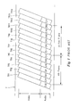
- Fig. 1 is a schematic plan view showing tracks (TR1-TR14) formed on a magnetic tape by a digital video tape recorder for recording digitized video and audio information thereon in a helical scanning system.
- a magnetic tape is helically wound around a rotary drum having magnetic heads, and video and audio information signals being digtized are recorded on the magnetic tape.
- the audio information signals of two channels (CH1, CH2) and the video information signal are recorded in a time sharing manner on each of tracks formed on a magnetic tape T.
- Video information signal of one video frame period included in nth frame is recorded on tracks TR2 to TR7, and the same included in the subsequent (n + 1)th frame is recorded on tracks TR8 to TR13.
- the audio information signal of CH1 is recorded on the track TR2 to TR4 and the audio information signal of the CH2 is recorded on the track TR5 to TR7.
- an amount of the audio information signal to be recorded during the one video frame period is made constant.
- the part of the track is preliminarily erased by a flying erase head. Then, new information signal is recorded on the erased part by a magnetic head. For instance, when the video information signals of the nth and (n + 1)th frames are renewed, the video signals of the tracks TR2 to TR13 are erased, and new video signals are recorded thereon.
- the reason of the preliminary erasure by using the flying erase head is to prevent an error rate at reproduction from increasing. otherwise an overwriting without such a preliminary erasure causes a large error rate at reproduction of the new information signal.
- a flying erase head having a track width larger than that of the track.
- this flying erase head causes a problem to erase parts of the tracks TR1 and TR14 in a track width direction, which should not be erased, resulting in an increase of the error rate because of a decrease of a signal level at reproduction.
- the error rate developed exceeds a limit of error correcting ability of the apparatus, the reproduced image is degraded in quality due to a partial loss of the information data.
- guard bands are provided between the tracks.
- these guard bands cause a problem to increase a track pitch between the tracks, resulting in a decrease of recording capability of the magnetic tape of a given length.
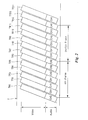
- Fig. 2 is a schematic plan view showing a track pattern having guard bands at every two tracks in the prior art.
- guard bands are provided between groups of two tracks as shown in Fig. 2. Thereby, it is possible to prevent the partial track erasure without decreasing much recording capacity upon renewal of recorded information as a unit of frame, and to prevent the increase of the error rate upon reproduction.
- a general object of the present invention is to provide information recording/reproducing apparatuses, in which the above disadvantages have been eliminated
- a specific object of the present invention is to provide an information recording/reproducing apparatus capable of renewing recorded information by rewriting one of two tracks abutted on each other without degrading a recording state of another track even when a guard band is not provided between the two tracks adjacent to each other or a very narrow guard band is provided therebetween.
- a more specific object of the present invention is to provide an information recording/reproducing apparatus for recording information signals on a recording medium as a track pattern having two tracks abutted on each other, and for reproducing the information signals recorded on the recording medium comprising: pre-reproduction means for reproducing the information signal recorded on one of the two tracks adjacent to each other on the recording medium upon rewriting for a renewal of the information signal recorded on another of the two tracks; and re-recording means for re-recording the information signal reproduced by the pre-reproduction means on an identical position as being initially recorded on the one of the two tracks in the recording medium.
- Another and more specific object of the present invention is to provide an information recording/reproducing apparatus capable of recording/reproducing video and audio information signals on/from a recording medium, the apparatus being constructed to utilize a recorded pattern of a group of two tracks adjacent to each other, each of the tracks having both a video area for recording the video information signal and an audio area for recording the audio information signal, the audio information signals of n (n > 1) channels being recorded in portions of the audio area of the tracks corresponding to one video information unit period, an auxiliary information signal indicating if the audio information signal is significant, being added to each of the audio information signals of m (m ⁇ 0, integer) channels among the audio information signals of the n channels, wherein the apparatus is capable of rewriting/editing the audio information signals of (n-m) channel except for the m channels, the apparatus comprising: pre-reproduction means for reproducing the audio information signal of one of the m channels prior to rewriting/editing the audio information signals recorded on one of the (n-m) channels of one of the two tracks abutted
- Other specific object of the present invention is to provide a method for recording/reproducing an information signal on a recording medium with a recorded pattern having groups of tracks adjacent to each other, the method comprising the steps of: reproducing an information signal recorded on one of the two tracks abutted on each other prior to rewriting/editing another of the two tracks; and recording the information signal reproduced on the same position on the recording medium again.
- Fig. 3 is a block diagram of a main part of a digital VTR of a first embodiment in the present invention.
- an input video signal is fed to a recording video signal processing circuit 12.
- the recording video signal processing circuit 12 performs predetermined recording processes such as dividing the signal into blocks, discrete cosine conversion (DCT) and quantization of the input video signal, and feeds processed video data to an video error correction encoding circuit (referred to as V error correction encoding circuit hereinafter) 14, and a timing information signal indicating one video frame period to a recording audio signal processing circuit 13 so as to synchronize the video data with audio data.
- the V error correction encoding circuit 14 encodes the inputted video data to error correction encoded data, and supplies them to a recording modulation circuit 16.
- audio input signals of two channels i.e., CH1 and CH2 are fed in parallel to the recording audio signal processing circuit 13 through a switch 11.
- the switch 11 Upon recording operation, the switch 11 is usually set to a terminal position "a".
- the audio input signals of CH1 and CH2 are fed to the recording audio signal processing circuit 13.
- the recording audio signal processing circuit 13 After having performed such as signal shuffling processing, the recording audio signal processing circuit 13 feeds the processed audio data of CH1 and CH2 to an audio error correction encoding circuit (referred to as A error correction encoding circuit hereinafter) 15.
- a error correction encoding circuit hereinafter
- the A error correction encoding circuit 15 feeds the encoded audio data of CH1 and CH2 to the recording modulation circuit 16 in such a timing that they form a tape pattern corresponding to the tracks TR2 to TR4 (CH-1) and the tracks TR5 to TR7 (CH-2) shown in Fig. 2, respectively.
- the recording modulation circuit 16 selects both the video data and the audio data in such a timing as corresponding to their positions to be recorded on the tracks, and adds synch-words to detect synchronization of the data upon reproduction, and performs a recording modulation encoding of the data to allow the data to be recorded on a magnetic tape T, and feed them to a recording amplifier 17.
- the recording amplifier 17 amplifies inputted signals and feeds them to a recording head 18 to record the inputted signals on the magnetic tape T.
- the recording amplifier 17 feeds the inputted signals to the recording head 18 according to a control signal A directing rewriting timing.
- a flying erase head 20 is provided ahead of the recording head 18, and a reproducing head 21 further ahead of the flying erase head 20 with respect to a rotational direction of the rotary drum shown with an arrow R.
- the data recorded on the magnetic tape T are erased by the flying erase head 20 in such a manner that an erase current is fed to the flying erase head 20 from an erase current amplifier 19 according to a timing indicated by a control signal B.
- it is porsible to directly overwrite data without erasing the previous data by the flying erase head 20.
- Outputted signal from the reproducing head 21 is fed to a reproducing demodulation circuit 23 through a reproduction amplifier 22.
- the reproducing demodulation circuit 23 demodulates the signals modulated at the recording, and separates the video data from the audio data, and feeds the audio and video data to an audio error correction decoding circuit (referred to as A error correction decoding circuit hereinafter) 24 and a video error correction decoding circuit (referred to as V error correction decoding circuit hereinafter) 25, respectively.
- the A and V error correction decoding circuits 24, 25 perform error correction decoding of the audio and video data referring to their error correction codes respectively, and supply the processed audio and video data to a reproduction audio signal processing circuit 26 and a reproduction video signal processing circuit 27 respectively. Further, if unrecoverable error data are found, the A error correction decoding circuit 24 performs flag adding processing for indicating the existence of the unrecoverable error data.
- the reproduction video signal processing circuit 27 performs a predetermined reproduction processing, i.e., reversing procedures of the recording processes such as dequantization, reverse-DCT, and rearrangement of the data, and outputs the processed signal as a reproduced video output signal, in addition, supplies the timing information signal indicating one video frame period to the reproduction audio signal processing circuit 26.
- a predetermined reproduction processing i.e., reversing procedures of the recording processes such as dequantization, reverse-DCT, and rearrangement of the data.
- the reproduction audio signal processing circuit 26 performs a reverse processing of the recording processing, wherein such reverse-shuffling is performed and so on.
- the circuit 26 restores the unrecoverable error data by using both preceding and succeeding sampled data as the sampling data of audio signal, and outputs the restored data as a reproduction audio signal.
- This reproduced audio signal is also inputted to the terminals "b" of the switch 11.
- the switch 11 Upon the normal recording, the switch 11 is (maintained to be) set to the terminals "a", and each of the inputted video and audio signals (CH1, CH2) undergoes certain recording processes through the recording video signal processing circuit 12, the recording audio signal processing circuit 13, the V and A error correction encoding circuits 14, 15, and the recording modulation circuit 16.
- the inputted video and audio signals are recorded on the magnetic tape T forming a tape pattern shown in Fig. 2 by the recording head 18. In this case, an erase current is not applied to the flying erase head 20.
- the data reproduced by the reproducing head 21 undergo certain reproducing progresses which are the reverse progressing of the recording progresses through the reproducing demodulation circuit 23, the A and V error correction decoding circuits 24, 25, and the reproduction audio and video signal processing circuits 26, 27, and the are outputted as a video output signal and an audio output signal.
- the switch 11 is set to the terminal "b" only for the audio output signal of CH2. And, the audio data of CH2 recorded on the tracks TR5 to TR7 are reproduced from the magnetic tape T by the reproducing head 21 prior to the editing recording, and the reproduced audio signal is inputted to the recording audio signal processing circuit 13 through the terminal "b" of the switch 11.
- a positional relation between the reproducing head 21 and the recording head 18 installed on the rotary drum (not shown), i.e., a preceding distance of the reproducing head 21 with respect to the recording head 18, is determined so that a rewriting timing of the audio data of CH1 to be rewritten accords with a timing of the reproduced audio data of CH2.
- the audio data of CH1 to be rewritten and the reproduced audio data of CH2 are applied to the recording audio signal processing circuit 13 in synchronization with each other, and are processed in the same manner as that of the ordinary recording operation.
- a number of audio sampled data to be recorded is determined to be a predetermined one, and the predetermined number is always maintained consistent.
- control signal A for operating the recording amplifier 17 in a period corresponding to the audio area of the tracks TR2 to TR7 is applied to the recording amplifier 17
- control signal B is applied to the erase current amplifier 19 to cause the flying erase head 20 to erase the data corresponding to the audio area of the tracks TR2 to TR7 prior to rewriting.
- the switch 11 is set to the terminal "b" only for the audio signal of CH1, and the same processing as mentioned above is performed.
- the audio data which are not an object of renewing is reproduced preceding to rewriting, and both the reproduced audio data and the new audio data to be rewritten are recorded on the respective tracks again.
- the number of audio sampled data recorded on the audio data area of the tracks TR5 to TR7 is a predetermined number.
- a sampling period of the audio input signal and the one video frame period are not locked.
- the sampling rate of the audio input signal is required to be converted in such a manner that the sampling rate is locked with the one frame period, resulting in a complicated circuit.
- the number of the audio sampled data is made variable upon recording, and the number representing the amount of the data is recorded on the audio data area together with the data to be recorded.
- both the audio sampling data inputted in the the video nth frame period and the number of the audio sampled data are recorded on the tracks TR2 to TR4 with respect to the audio data of CH1 and the tracks TR5 to TR7 with respect to the audio data of CH2.
- the audio sampled data are reproduced being referred to the number of data in one frame period.
- the number of the sampled data to be recorded in one video frame period may be deviated every video frame.
- the numbers of the audio sampled data of CH1 and CH2 recorded on the tracks TR2 to TR13 of the audio area at an initial state does not always coincide with the number of the audio sampled data reproduced therefrom in advance of rewriting.
- the number of the sampled data to be recorded is predetermined.
- the number of the audio sampled data being recorded is larger than the number of sampled data capable of being recorded in the nth and (n + 1)th frame period, one part of the sampled data reproduced from the tracks TR5 to TR7 and TR11 to TR13 in advance of rewriting is impossible to be recorded again.
- a dropout of sampled data occurs between the (n + 1)th and (n + 2)th frames. The dropout of sampled data causes abnormal sound in the reproduction.
- Fig. 4 is a block diagram showing a main part of a digital VTR of a second embodiment in the present invention.
- a construction shown in Fig. 4 is employed instead of the one shown in Fig. 3.
- the switch 11 shown in Fig. 3 is removed, and instead of that the switch 31 is provided between the recording audio signal processing circuit 13 and the A error correction encoding circuit 15, and the data outputted from the A error correction decoding circuit 24 is applied to terminals "b" of the switch 31 through a delay circuit 32.
- Other construction is the same as that of the first embodiment shown in Fig. 3.
- the A error correction decoding circuit 24 detects and corrects the data error referring to the error correction code added at recording as mentioned in the first embodiment. When a unrecoverable error data is detected, the A error correction decoding circuit 24 converts a value of the error data to a value of inhibited data. For instance, in a case of 16 bit data, a value of [8000h (h denotes hexadecimal system)] is given as the inhibited data.
- the delay circuit 32 feeds its input signal to the switch 31 by causing a delay time corresponding to a sum of a time required for signal processing in the reproducing audio signal processing circuit 26 and a time required for signal processing in the recording audio signal processing circuit 13.
- the switch 31 is set to the terminal "b" for the audio data of CH2 for a predetermined switching period when the audio data of CH1 is rewritten. This switching period is controlled so that the switch 31 is set to the terminal "b” only while the audio data of CH2 of the track TR5 are outputted from the delay circuit 32. In this case, the renewed audio data of CH1 to be rewritten on the tracks TR2 to TR4 are also applied to the A error correction encoding circuit 15 through the switch 31.
- the A error correction encoding circuit 15 performs both coding of the audio sampled data to be recorded on the audio area of the tracks TR2 to TR4 and encoding of the audio sampled data inputted from the delay circuit 32 to be recorded on the audio area of the track TR5 . After that the A error correction encoding circuit 15 applies the audio data of CH1 and CH2 to the recording modulation circuit 16 in a timing corresponding to the tracks TR2 to TR4 and the track TR5, respectively.
- the recording amplifier 17 is controlled by the control signal A in such a manner that it only operates during a period corresponding to the audio areas of the tracks TR2 to TR4 and the track TR5.
- the erase current amplifier 19 is also controlled by the control signal B in such a manner that the flying erase head 20 erases only the audio data in the tracks TR2 to TR5.
- the rewriting of the audio data of CH1 in the (n + 1)th frame is performed in the same manner as mentioned above.
- it is the audio data of CH2 of the track TR11 from which the signal is reproduced in advance of rewriting and re-recorded thereon, because a part of the audio data of the track TR11 is erased by the flying erase head 20.
- the circuit 26 Upon normal reproducing, when such data as having the inhibited value (8000h) outputted from the A error correction decoding circuit 24 is inputted to the reproducing audio signal processing circuit 26, the circuit 26 handles it as the unrecoverable data. In other words, an interpolated value obtained by using the two data adjacent to the unrecoverable data replaces the value of the unrecoverable data. Thus, it is possible to reproduce the audio data normally.
- the outputted data from the A error correction decoding circuit 24 is directly supplied to the A error correction encoding circuit 15 through the delay circuit 32.
- the delay circuit 32 it is possible to prevent the abnormal sound from occurring at the editing part even when the number of the audio data to be recorded during one frame period is deviated or variable, because the number of the sampled data to be rewritten coincides with the number of the data already recorded.
- error data is made to be the inhibited data value and is re-recorded on the corresponding track, it is not necessary to provide an error correction circuit (a circuit for performing interpolation correction) in the path for feeding back the audio data which are not the object of rewriting, from the reproducing system to the recording system, resulting in a simple construction of the circuit.
- an error correction circuit a circuit for performing interpolation correction
- the track to be reproduced prior to rewriting and re-recording is limited to only one track (the track TR5 of which a part is erased by the flying erase head 20). This allows other tracks (TR6, TR7) to remain as they are, resulting in a prevention of dropout of sound when the recording head 18 malfunctions.
- a third embodiment of the present invention is conceived, in which the editing operation is intended to be instantly stopped when the number of the error data is beyond the limit of the error data correcting ability of the system.
- Fig. 5 is a block diagram showing a main part of a digital VTR of a third embodiment in the present Invention.
- an audio signal processing system of four channels to allow four channel audio signals to record and reproduce on the tracks at both normal and editing recording.
- an error encode counting circuit 51 for counting unrecoverable error data at the audio reproduction
- a system control circuit 52 for controlling the system of the digital VTR corresponding to an output from the error code counting circuit 51.
- the recording audio signal processing circuit 13, the A error correction encoding circuit 15, the A error correction decoding circuit 24, the reproducing audio signal processing circuit 26, the swith 31 and the delay circuit 32 shown in Fig. 4 are respectively replaced with a recording audio signal processing circuit 13A, an A error correction encoding circuit 15A, an A error correction decoding circuit 24A, a reproducing audio signal processing circuit 26A, a switching circuit 31A and a delay circuit 32A, each having four channels to allow the four channel audio signals to be recorded and reproduced on the tracks of the magnetic tape T. Further, the output signal from the A error correction decoding circuit 24A is applied to the error code counting circuit 51.
- the error correction code of the third embodiment has a structure of a product code composed of an inner correction code and an outer correction code.
- Each of the inner and outer codes has a Reed Solomon code in which eight bits are made as one symbol or one code word.
- the inner correction code is made of (88, 80) Reed Solomon code and the outer correction code is made of (150, 140) Reed Solomon code.
- one sampled data is made of 16 bits, and are divided into two parts, i.e., an upper half of 8 bits and a lower half of 8 bits which make a symbol or a byte, respectively. Thus, the upper and lower sections of 8 bits make up a pair of symbols.
- the digital VTR of the second embodiment has a system control circuit corresponding to the one shown in Fig. 5, however, it is not depicted in Fig. 4 because it has only ordinary functions of the digital VTR.
- Fig. 7 is a schematic plan view showing another track pattern having four channels for audio data.
- the recorded pattern on the magnetic tape becomes as shown in Fig. 7.
- the audio data of CH1 and CH4 are recorded on the tracks TR2 to TR4 and those of CH2 and CH3 are recorded on the tracks TR5 to TR7.
- the editing recording operation is performed as follows.
- the audio data of CH3 of the track TR5 is reproduced by the reproducing head 21 prior to rewriting, and the data reproduced are fed to the A error correction decoding circuit 24A through the reproducing demodulation circuit 23.
- the A error correction decoding circuit 24A After decoding the inner and outer correcting codes, the A error correction decoding circuit 24A corrects error symbols when it identifies the number of the error symbols to be within its ability of error correction.
- the A error correction decoding circuit 24A identifies the number of the error symbols to be beyond its ability of error correction, it converts the error detected symbols and the other part of the pairs with respect to the error detected symbols (i.e, when the error symbol is the upper half of 8 bits in the pair, the other part of the pair is the lower half of 8 bits or when the error symbol is the lowr half of 8 bits in the pair, the other part of the pair is the upper half of 8 bits) into error codes, and outputs them.
- the error detecting ability is superior to the error correcting ability, thus it is possible to perform such error code conversion even when it is impossible to perform the error correction because the position of the error data can be detected.
- the inhibited value of 8000h as mentioned in the second embodiment is divided in two error codes, i.e., an upper Half of 8 bits and a lower half thereof.
- the output signals from the A error correction decoding circuit 24A are fed to the reproducing audio signal processing circuit 26A, the delay circuit 32A and the error code counting circuit 51.
- the error code counting circuit 51 counts the number of the error codes in the data produced from the track TR5. When the number of the error codes is larger than the predetermined number, the error code counting circuit 51 notifies the fact to the system control circuit 52 (the notice thereof is referred to as an majority error code notice hereinafter).
- the system control circuit 52 which has also functions to control overall operations of the digital VTR, receives the majority error code notice, it instantly stops operation of the erase current amplifier 19 and the recording amplifier 17 and running the magnetic tape T, and displays on a display section (not shown) the fact that the number of the error code is larger than the predetermined number.
- the editing operation is successively performed, i.e., the audio data of CH1 of the tracks TR2 to TR4 and the audio data of CH3 of the track TR5 are erased by the flying erase head 20.
- both the outputs from the delay circuit 32A and the outputs from the recording audio signal processing circuit 13A are fed to the switching circuit 31A.
- the switching circuit 31A is set to the terminal "b" for the audio data of CH3 for a predetermined period, and the output from the delay circuit 32A is fed to the A error correction encoding circuit 15A.
- the A error correction encoding circuit 15A performs the error correction encoding of the audio data of CH1 to be recorded on the tracks TR2, TR3 and TR4, and of the data outputted from the delay circuit 32A to feed all of them to the recording modulation circuit 16. Then, the same processing as mentioned in the second embodiment is performed, resulting in that the audio data of CH1 is rewritten on the tracks TR2, TR3 and TR4, and the audio data of CH3 is re-recorded on the track TR5.
- the audio data of CH3 recorded on the track TR5 are reproduced prior to rewriting, and the audio data of CH1 recorded on the tracks TR2 to TR4 and the audio data of CH3 recorded on the track 5 are erased Then, the audio data of CH3 are error correction-decoded and are delayed at a predetermined time by the delay circuit 32A. As a result, the audio data of CH3 are again error correction-encoded by the A error correction encoding circuit 15A, and are again re-recorded on the audio area of CH3 of the track TR5.
- the editing recording is instantly stopped.
- the recording audio data are replaced with the ones greatly degraded compared to the original data.
- a forcible editing recording mode is added to allow the user to perform the editing recording operation successively regardless of the warning message.
- the user may select the forcible editing recording mode and perform the editing recording again.
- the function of the error code counting circuit 51 for counting the number of the error codes as mentioned in the third embodiment is replaced with a function of counting a number of unrecoverable flag as mentioned hereinafter.
- Other basic structures are the same as those of the third embodiment shown in Fig. 5.
- the A error correction decoding circuit 24A decodes the inner correcting code. When the decoded error data is within the data correcting ability of the system, the decoded error data is corrected. When the decoded error data is beyond the data correcting ability of the system or the result of correction of the error data is less reliable, one unrecoverable flag is made active and is added to the overall inner correcting code. When the error data can be corrected, the unrecoverable flag is made inactive. Further, the A error correction decoding circuit 24A decodes the outer correcting code. When the decoded error data is within the data correcting ability of the system, the decoded error data is corrected.
- each of the error symbol of the audio sampled data and the other of the pair thereof is replaced with interpolation value by using preceding and succeeding sampled data adjacent to the error symbol or the other part of the pair.
- the A error correction decoding circuit 24A outputs the unrecoverable flag together with the audio sampled data.
- An error correction unrecoverable flag is provided at every inner correction code.
- the number of the unrecoverable flags is outputted corresponding to the number of the inner correction codes in the audio area of CH3 of the track TR5.
- the error code couting circuit 51 counts only the number of the error correction unrecoverable flags being activated.
- the error code counting circuit 51 When the number of the error correction unrecoverable flags being activated is larger than the predetermined number, the error code counting circuit 51 notifies the fact to the system control circuit 52. The rest of the processes is the same as those in the third embodiment.
- the digital VTR of the fourth embodiment it has an advantage that it is unnecessary to inhibit a certain value as a value of an audio sampled data, resulting in a simple structure.
- the audio areas of CH1 and CH2 shown in Fig. 7 are used as the audio data recording areas, and the audio areas of CH3 and CH4 are used as dummy data areas.
- a dummy flag (referred to as a D flag) for discriminating a significant audio data or not from a dummy data, wherein a dummy flag activated represents a dummy data.
- a basic structure of the digital VTR capable of recording/reproducing four audio channels has approximately the same construction as that of the third embodiment shown in Fig. 5, however, the information to be added to the audio data is performed by the A error correction encoding circuit 15A.
- the audio data are recorded on the audio areas of CH3 and CH4, the D flags thereof are recorded thereon by being inactivated.
- Fig. 6 is a block diagram showing a main part of a digital VTR of a fifth embodiment capable of recording/ reproducing the two channels of audio data, wherein the track pattern shown in Fig. 7 is employed.
- the digital VTR of fifth embodiment is constructed based on the specification for the recorded tape pattern of four channels shown in Fig. 7, and is possible to record/ reproduce the information signals from two channels.
- the basic configuration for processing the video and audio signals in the fifth embodiment is approximately the same as that of the digital VTR shown in Fig. 4, however, in the fifth embodiment the dummy data are fed to the recording audio signal processing circuit 13A instead of the audio data of the CH3 and CH4.
- the recording audio signal processing circuit 13A and the A error correction encoding circuit 15A respectively have a circuit for four channels.
- the switch 31 and the delay circuit 32 are not provided, and a D flag discriminating circuit 53 for discriminating the D flag activated from the D flag inactivated and the system control circuit 52 for stopping the editing operation responsible to an output signal from the D flag discriminating circuit 53 are provided.
- the digital VTR shown in Fig. 6 outputs only the audio data of CH1 and CH2 as the reproduced audio signal, but has a function of reproduction by discriminating the audio areas of CH3 and CH4 from the those of the CH1 and the CH2 recorded on the magnetic tape T.
- the D flag discriminating circuit 53 discriminates the D flag activated from the D flag inactivated, anti notifies the result to the system control circuit 52.
- the system control circuit 52 continues the editing recording because a loss of the audio data of CH3 is no problem. Specifically, the audio data of CH1 of the tracks TR2 to TR4 and the audio data of CH3 of the track TR5 to TR7 are erased by the flying erase head 20.
- the A error correction encoding circuit 15A performs the error correction encoding of the audio data of CH1 to be re-written and of the dummy data to be written on the audio area of CH3, and they are recorded on the audio area of CH1 of the tracks TR2 to TR4 and the audio area of CH3 of the tracks TR5 to TR7 through the recording modulating circuit 16, the recording amplifier 17 and the recording head 18.
- the D flag of the audio data of CH3 is made to be activated.
- the system control circuit 52 instantly stops operations of the erase current amplifier 19 and the recording amplifier 17 as well as running of the magnetic tape T, and displays on the display section (not shown) the message that the significant audio data is recorded on the audio area of CH3 and the data will be lost if the audio data of CH1 is rewritten.
- a forcible editing mode for successively processing the editing recording operation by ignoring the D flag activated, and the forcible editing mode can be optionally selected by the user.
- the user can select the forcible mode to continue the editing recording as long as the loss of the audio data of CH3 is allowable to the user.
- a flag (auxiliary information) for indicating the presence of the significant audio data is added to the audio data of CH3 and CH4. Accordingly, upon performing the editing recording by using a low cost type audio two channel editor, it is possible to prevent the significant data from being erased even when the magnetic tape T recorded with the significant four channel audio data is erroneously installed in the low cost type audio two channel editor.
- the present invention is not limited to the embodiments mentioned in the foregoing, and various modifications thereof is available.
- the information recorded on the magnetic tape is not limited to the video and audio information but any information is available.
- the recording medium is not limited to the magnetic tape but it is applicable to the magnetic disc on which information is recorded on a plurality of tracks without guard bands or with narrow guard bands.
- the recorded pattern in the embodiments mentioned in the foregoing is shown as such that the audio data of CH1 and CH2 are alternately recorded on every three tracks, but it is not limited to that. It is possible to employ such a tape pattern as the audio data of CH1 and CH2 are recorded every other track or every four tracks.
- the video and audio signals are respectively fed to the corresponding error correction encoding circuit and error correction decoding circuit, but it is possible to feed them to a common error correction encoding circuit and to an error correction decoding circuit.
- the video signal processing circuit, and the error correction encoding circuit and the error correction decoding circuit are electrically connected through a bus system, and the video and audio signals are fed in a time divisional manner.
Landscapes
- Engineering & Computer Science (AREA)
- Multimedia (AREA)
- Signal Processing (AREA)
- Signal Processing For Digital Recording And Reproducing (AREA)
- Television Signal Processing For Recording (AREA)
- Management Or Editing Of Information On Record Carriers (AREA)
- Optical Recording Or Reproduction (AREA)
Applications Claiming Priority (6)
| Application Number | Priority Date | Filing Date | Title |
|---|---|---|---|
| JP27406596 | 1996-09-24 | ||
| JP274065/96 | 1996-09-24 | ||
| JP27406596 | 1996-09-24 | ||
| JP32795996 | 1996-11-22 | ||
| JP327959/96 | 1996-11-22 | ||
| JP8327959A JPH10154388A (ja) | 1996-09-24 | 1996-11-22 | 情報記録再生装置及び方法 |
Publications (2)
| Publication Number | Publication Date |
|---|---|
| EP0831486A2 true EP0831486A2 (fr) | 1998-03-25 |
| EP0831486A3 EP0831486A3 (fr) | 1999-12-29 |
Family
ID=26550880
Family Applications (1)
| Application Number | Title | Priority Date | Filing Date |
|---|---|---|---|
| EP97402200A Withdrawn EP0831486A3 (fr) | 1996-09-24 | 1997-09-22 | Appareil d'enregistrement/de reproduction d'informations et méthode |
Country Status (3)
| Country | Link |
|---|---|
| US (1) | US6052241A (fr) |
| EP (1) | EP0831486A3 (fr) |
| JP (1) | JPH10154388A (fr) |
Families Citing this family (4)
| Publication number | Priority date | Publication date | Assignee | Title |
|---|---|---|---|---|
| US6393199B1 (en) * | 1997-03-20 | 2002-05-21 | Recording Physics, Inc. | Apparatus and method for high speed recording of video signals |
| WO1999012165A1 (fr) * | 1997-09-02 | 1999-03-11 | Sony Corporation | Procede et appareil de post enregistrement sur support d'enregistrement numerique et procede et appareil de lecture du support d'enregistrement numerique |
| US7768729B2 (en) * | 2008-01-31 | 2010-08-03 | Hitachi Global Storage Technologies Netherlands B.V. | Method, system, and computer program product for estimating adjacent track erasure risk by determining erase band width growth rates |
| JP2017009663A (ja) * | 2015-06-17 | 2017-01-12 | ソニー株式会社 | 録音装置、録音システム、および、録音方法 |
Family Cites Families (10)
| Publication number | Priority date | Publication date | Assignee | Title |
|---|---|---|---|---|
| DE2847440A1 (de) * | 1978-11-02 | 1980-05-22 | Basf Ag | Verfahren und anordnung zum veraendern von videoaufzeichnungen mit oder ohne audioinformation |
| CA1133639A (fr) * | 1979-01-30 | 1982-10-12 | Masato Tanaka | Methode et appareil de decoupage de signaux numeriques enregistres sur un support |
| JPS5792472A (en) * | 1980-11-25 | 1982-06-09 | Sony Corp | Editing method for pcm signal |
| US4899232A (en) * | 1987-04-07 | 1990-02-06 | Sony Corporation | Apparatus for recording and/or reproducing digital data information |
| JP2553668B2 (ja) * | 1988-10-13 | 1996-11-13 | 松下電器産業株式会社 | 磁気記録方法 |
| KR950009383B1 (ko) * | 1990-06-29 | 1995-08-21 | 마쯔시다 덴기 산교 가부시기가이샤 | 디지틀음성신호기록방법 |
| US5299072A (en) * | 1990-11-21 | 1994-03-29 | Matsushita Electric Industrial Co., Ltd. | Video and audio signal recording apparatus with editing-use erase heads |
| JPH04344372A (ja) * | 1991-05-22 | 1992-11-30 | Hitachi Ltd | ディジタル信号記録再生装置 |
| JP3089974B2 (ja) * | 1995-02-13 | 2000-09-18 | 日本ビクター株式会社 | 信号記録方法及び映像信号処理装置 |
| JPH09106663A (ja) * | 1995-10-06 | 1997-04-22 | Sony Corp | 編集用ビデオテープレコーダ |
-
1996
- 1996-11-22 JP JP8327959A patent/JPH10154388A/ja active Pending
-
1997
- 1997-09-22 EP EP97402200A patent/EP0831486A3/fr not_active Withdrawn
- 1997-09-23 US US08/935,991 patent/US6052241A/en not_active Expired - Fee Related
Also Published As
| Publication number | Publication date |
|---|---|
| EP0831486A3 (fr) | 1999-12-29 |
| US6052241A (en) | 2000-04-18 |
| JPH10154388A (ja) | 1998-06-09 |
Similar Documents
| Publication | Publication Date | Title |
|---|---|---|
| KR900000630B1 (ko) | 정지헤드로서 디지탈신호의 기록 및 재생을 위한 방법과 그 장치 | |
| EP0084952A2 (fr) | Dispositif d'enregistrement de signaux numériques | |
| US5731922A (en) | Image recording system performing error correction repeatedly with the same check fields | |
| US6154866A (en) | Reproducing apparatus, error correcting unit and error correcting method | |
| JPWO1998014940A1 (ja) | 再生装置、誤り訂正装置及び誤り訂正方法 | |
| US7027720B2 (en) | Magnetic tape recording apparatus and method, magnetic tape reading apparatus and method, recording medium used therewith, and format for magnetic tape | |
| JPH07107782B2 (ja) | ディジタルテープレコーダ | |
| EP0615382B1 (fr) | Appareil d'enregistrement de signaux digitaux | |
| KR930016948A (ko) | 디지탈신호 기록재생장치 및 디지탈신호 기록재생방법 | |
| US6052241A (en) | Method and apparatus for minimizing erasure errors during information recording/reproducing | |
| KR100417204B1 (ko) | 디지털기록재생장치 | |
| JP3303368B2 (ja) | 伝送装置及び方法、伝送システム | |
| US5321561A (en) | Format for recording digital audio onto magnetic tape with enhanced editing and error correction capability | |
| US6334024B1 (en) | Helical scan data recording apparatus and a helical scan data reproducing apparatus | |
| EP0736869B1 (fr) | Méthode et appareil pour enregistrer des signaux numériques | |
| US5483388A (en) | Information recording and reproducing apparatus forming plural kinds of error detection or correction codes | |
| JP4007880B2 (ja) | ディジタルvtr | |
| JP2637089B2 (ja) | デイジタルvtrの信号処理方式 | |
| JP3536647B2 (ja) | 情報記録再生方法及び装置 | |
| JP2724632B2 (ja) | 多トラックデジタルテープレコーダ | |
| JP3252532B2 (ja) | ディジタルデータ記録方法とその装置 | |
| EP0624977A2 (fr) | Appareil de traitement de données numériques | |
| JP2000030231A (ja) | 磁気記録再生方法及び磁気記録再生装置 | |
| Davies | Formatting and Coding the Audio in the DTTR | |
| JPS6244348B2 (fr) |
Legal Events
| Date | Code | Title | Description |
|---|---|---|---|
| PUAI | Public reference made under article 153(3) epc to a published international application that has entered the european phase |
Free format text: ORIGINAL CODE: 0009012 |
|
| AK | Designated contracting states |
Kind code of ref document: A2 Designated state(s): DE FR GB |
|
| PUAL | Search report despatched |
Free format text: ORIGINAL CODE: 0009013 |
|
| AK | Designated contracting states |
Kind code of ref document: A3 Designated state(s): AT BE CH DE DK ES FI FR GB GR IE IT LI LU MC NL PT SE |
|
| RIC1 | Information provided on ipc code assigned before grant |
Free format text: 7G 11B 27/036 A, 7G 11B 15/18 B, 7G 11B 27/34 B, 7G 11B 27/36 B |
|
| 17P | Request for examination filed |
Effective date: 20000504 |
|
| AKX | Designation fees paid |
Free format text: DE FR GB |
|
| 17Q | First examination report despatched |
Effective date: 20010412 |
|
| STAA | Information on the status of an ep patent application or granted ep patent |
Free format text: STATUS: THE APPLICATION IS DEEMED TO BE WITHDRAWN |
|
| 18D | Application deemed to be withdrawn |
Effective date: 20020422 |