EP0831945B1 - Technik zum vorfüllen und rezirkulieren einer flüssigkeit in einer dialysemaschine - Google Patents
Technik zum vorfüllen und rezirkulieren einer flüssigkeit in einer dialysemaschine Download PDFInfo
- Publication number
- EP0831945B1 EP0831945B1 EP96917239A EP96917239A EP0831945B1 EP 0831945 B1 EP0831945 B1 EP 0831945B1 EP 96917239 A EP96917239 A EP 96917239A EP 96917239 A EP96917239 A EP 96917239A EP 0831945 B1 EP0831945 B1 EP 0831945B1
- Authority
- EP
- European Patent Office
- Prior art keywords
- arterial
- dialyzer
- venous
- blood
- line
- Prior art date
- Legal status (The legal status is an assumption and is not a legal conclusion. Google has not performed a legal analysis and makes no representation as to the accuracy of the status listed.)
- Expired - Lifetime
Links
Images


Classifications
-
- A—HUMAN NECESSITIES
- A61—MEDICAL OR VETERINARY SCIENCE; HYGIENE
- A61M—DEVICES FOR INTRODUCING MEDIA INTO, OR ONTO, THE BODY; DEVICES FOR TRANSDUCING BODY MEDIA OR FOR TAKING MEDIA FROM THE BODY; DEVICES FOR PRODUCING OR ENDING SLEEP OR STUPOR
- A61M1/00—Suction or pumping devices for medical purposes; Devices for carrying-off, for treatment of, or for carrying-over, body-liquids; Drainage systems
- A61M1/36—Other treatment of blood in a by-pass of the natural circulatory system, e.g. temperature adaptation, irradiation ; Extra-corporeal blood circuits
- A61M1/3621—Extra-corporeal blood circuits
- A61M1/3643—Priming, rinsing before or after use
-
- A—HUMAN NECESSITIES
- A61—MEDICAL OR VETERINARY SCIENCE; HYGIENE
- A61M—DEVICES FOR INTRODUCING MEDIA INTO, OR ONTO, THE BODY; DEVICES FOR TRANSDUCING BODY MEDIA OR FOR TAKING MEDIA FROM THE BODY; DEVICES FOR PRODUCING OR ENDING SLEEP OR STUPOR
- A61M1/00—Suction or pumping devices for medical purposes; Devices for carrying-off, for treatment of, or for carrying-over, body-liquids; Drainage systems
- A61M1/36—Other treatment of blood in a by-pass of the natural circulatory system, e.g. temperature adaptation, irradiation ; Extra-corporeal blood circuits
- A61M1/3621—Extra-corporeal blood circuits
- A61M1/3622—Extra-corporeal blood circuits with a cassette forming partially or totally the blood circuit
- A61M1/36225—Extra-corporeal blood circuits with a cassette forming partially or totally the blood circuit with blood pumping means or components thereof
-
- A—HUMAN NECESSITIES
- A61—MEDICAL OR VETERINARY SCIENCE; HYGIENE
- A61M—DEVICES FOR INTRODUCING MEDIA INTO, OR ONTO, THE BODY; DEVICES FOR TRANSDUCING BODY MEDIA OR FOR TAKING MEDIA FROM THE BODY; DEVICES FOR PRODUCING OR ENDING SLEEP OR STUPOR
- A61M1/00—Suction or pumping devices for medical purposes; Devices for carrying-off, for treatment of, or for carrying-over, body-liquids; Drainage systems
- A61M1/36—Other treatment of blood in a by-pass of the natural circulatory system, e.g. temperature adaptation, irradiation ; Extra-corporeal blood circuits
- A61M1/3621—Extra-corporeal blood circuits
- A61M1/3622—Extra-corporeal blood circuits with a cassette forming partially or totally the blood circuit
- A61M1/36226—Constructional details of cassettes, e.g. specific details on material or shape
- A61M1/362262—Details of incorporated reservoirs
-
- A—HUMAN NECESSITIES
- A61—MEDICAL OR VETERINARY SCIENCE; HYGIENE
- A61M—DEVICES FOR INTRODUCING MEDIA INTO, OR ONTO, THE BODY; DEVICES FOR TRANSDUCING BODY MEDIA OR FOR TAKING MEDIA FROM THE BODY; DEVICES FOR PRODUCING OR ENDING SLEEP OR STUPOR
- A61M1/00—Suction or pumping devices for medical purposes; Devices for carrying-off, for treatment of, or for carrying-over, body-liquids; Drainage systems
- A61M1/36—Other treatment of blood in a by-pass of the natural circulatory system, e.g. temperature adaptation, irradiation ; Extra-corporeal blood circuits
- A61M1/3621—Extra-corporeal blood circuits
- A61M1/3622—Extra-corporeal blood circuits with a cassette forming partially or totally the blood circuit
- A61M1/36226—Constructional details of cassettes, e.g. specific details on material or shape
- A61M1/362266—Means for adding solutions or substances to the blood
-
- A—HUMAN NECESSITIES
- A61—MEDICAL OR VETERINARY SCIENCE; HYGIENE
- A61M—DEVICES FOR INTRODUCING MEDIA INTO, OR ONTO, THE BODY; DEVICES FOR TRANSDUCING BODY MEDIA OR FOR TAKING MEDIA FROM THE BODY; DEVICES FOR PRODUCING OR ENDING SLEEP OR STUPOR
- A61M1/00—Suction or pumping devices for medical purposes; Devices for carrying-off, for treatment of, or for carrying-over, body-liquids; Drainage systems
- A61M1/36—Other treatment of blood in a by-pass of the natural circulatory system, e.g. temperature adaptation, irradiation ; Extra-corporeal blood circuits
- A61M1/3621—Extra-corporeal blood circuits
- A61M1/3643—Priming, rinsing before or after use
- A61M1/3644—Mode of operation
- A61M1/3646—Expelling the residual body fluid after use, e.g. back to the body
-
- A—HUMAN NECESSITIES
- A61—MEDICAL OR VETERINARY SCIENCE; HYGIENE
- A61M—DEVICES FOR INTRODUCING MEDIA INTO, OR ONTO, THE BODY; DEVICES FOR TRANSDUCING BODY MEDIA OR FOR TAKING MEDIA FROM THE BODY; DEVICES FOR PRODUCING OR ENDING SLEEP OR STUPOR
- A61M1/00—Suction or pumping devices for medical purposes; Devices for carrying-off, for treatment of, or for carrying-over, body-liquids; Drainage systems
- A61M1/36—Other treatment of blood in a by-pass of the natural circulatory system, e.g. temperature adaptation, irradiation ; Extra-corporeal blood circuits
- A61M1/3621—Extra-corporeal blood circuits
- A61M1/3643—Priming, rinsing before or after use
- A61M1/3644—Mode of operation
- A61M1/3647—Mode of operation with recirculation of the priming solution
-
- A—HUMAN NECESSITIES
- A61—MEDICAL OR VETERINARY SCIENCE; HYGIENE
- A61M—DEVICES FOR INTRODUCING MEDIA INTO, OR ONTO, THE BODY; DEVICES FOR TRANSDUCING BODY MEDIA OR FOR TAKING MEDIA FROM THE BODY; DEVICES FOR PRODUCING OR ENDING SLEEP OR STUPOR
- A61M2205/00—General characteristics of the apparatus
- A61M2205/12—General characteristics of the apparatus with interchangeable cassettes forming partially or totally the fluid circuit
- A61M2205/123—General characteristics of the apparatus with interchangeable cassettes forming partially or totally the fluid circuit with incorporated reservoirs
-
- A—HUMAN NECESSITIES
- A61—MEDICAL OR VETERINARY SCIENCE; HYGIENE
- A61M—DEVICES FOR INTRODUCING MEDIA INTO, OR ONTO, THE BODY; DEVICES FOR TRANSDUCING BODY MEDIA OR FOR TAKING MEDIA FROM THE BODY; DEVICES FOR PRODUCING OR ENDING SLEEP OR STUPOR
- A61M39/00—Tubes, tube connectors, tube couplings, valves, access sites or the like, specially adapted for medical use
- A61M39/10—Tube connectors; Tube couplings
Definitions
- the present.invention relates to a new and improved dialysis system and technique for automatically priming and recirculating fluid through a dialyzer and a disposable blood tubing set which connects a patient to a dialysis machine.
- a dialysis system is used as a substitute for the natural kidney functions of a human body.
- the dialysis system cleans the blood of the natural accumulation of bodily wastes by separating the wastes from the blood outside or extracorporeally of the body. The separated wastes are discharged and the cleansed blood is returned to the body.
- the dialysis system consists of a dialysis machine, a dialyzer, a disposable blood tubing set and a supply of chemicals for producing a dialysate solution used within the dialyzer.
- the dialyzer is used with the dialysis machine to separate the wastes from the blood.
- the dialyzer includes a porous membrane located within a closed housing which effectively-separates the housing into a blood compartment and a dialysate or filtrate compartment.
- the blood removed from the patient flows through the disposable blood tubing set and the blood side of the dialyzer.
- the dialysate solution prepared from the chemicals is passed through the dialysate side of the dialyzer.
- the wastes from the blood pass through the membrane by osmosis, ionic transfer or fluid transport into the dialysate and, depending upon the type of dialysis treatment, desirable components from the dialysate may pass in the opposite direction through the membrane and into the blood.
- the transfer of the wastes into the dialysate cleanses the blood while allowing the desired components from the dialysate to enter the bloodstream.
- the transfer of blood between the patient and the dialyzer occurs within a disposable blood tubing set.
- the blood tubing set and the dialyzer represent a closed extracorporeal path through which the patient's blood travels.
- the blood tubing set includes an arterial line connected to an arterial reservoir for drawing blood from a patient, a venous line connected to a venous reservoir for returning blood to the patient, and a number of other lines for connecting a pump and the dialyzer between the arterial and venous reservoirs.
- both must be primed with a sterile saline solution to remove air from the extracorporeal circuit.
- the saline solution is recirculated through the blood tubing set and the dialyzer to produce a stabilized flow and remove additional trapped air from within the extracorporeal circuit.
- the priming and recirculating process also serves to clean the dialyzer and flush the dialyzer membrane of any debris or chemicals remaining from a prior use.
- a patient reuses the same dialyzer for subsequent dialysis treatments, that dialyzer must be cleaned with a disinfectant or sterilant solution.
- the sterilant itself must be cleaned from the dialyzer prior to each dialysis treatment.
- Such a cleaning procedure effectively takes place when the dialyzer undergoes the priming and recirculating process discussed above.
- the dialyzer is flushed with saline solution which removes a majority of the sterilant.
- the dialysis machine can be commanded to remove or "pull" a predetermined flow of saline directly from the dialyzer.
- This predetermined flow corresponds to "pulling off" a predetermined amount of fluid (or weight) from a patient during dialysis, and is commonly referred to as “ultrafiltration.” Removing saline by ultrafiltration during recirculation of the saline solution thus allows the remaining sterilant within the dialyzer to be removed as it mixes with the saline. The saline that is removed by ultrafiltration is replenished from a saline source connected to the extracorporeal circuit so that no additional air is added to the extracorporeal circuit during recirculation.
- a typical priming sequence on a conventional dialysis machine requires that the operator connect the outlet of the dialysis machine (i.e., the venous line) to a saline source and then operate the dialysis machine in reverse to fill the extracorporeal circuit with saline.
- the priming solution passes through the dialyzer and, in light of the reverse flow, exits the extracorporeal circuit through the dialysis machine's input line (i.e., the arterial line) which the operator connects to a waste basin or drain to dispose of the priming solution.
- the initial priming solution is discarded because it may contain relatively large quantities of sterilant flushed from the dialyzer when the dialyzer is sterilized and reused following a previous dialysis treatment.
- the operator must disconnect the venous and arterial lines of the blood tubing set from the saline source and waste basin, respectively, and then connect the venous and arterial lines together (i.e., short circuiting the patient).
- the operator then switches the dialysis machine from its reverse operation and operates the machine normally to recirculate the saline solution through the extracorporeal circuit.
- the operator must further connect the saline source to a different portion of the circuit so that additional saline may be supplied to replace the saline removed by ultrafiltration during recirculation.
- WO-A-88/06460 describes a blood tubing set used with a platelet separator/plasma filter device.
- a number of pumps and clamps are positioned along the blood tubing set to aid in the priming and purging procedure, while a sterile enclosure holds the collection and return needles of the blood tubing set during the priming and purging procedures.
- the sterile enclosure allows fluid to communicate between the collection and return needles and thus provides for continuous circulation through the blood tubing set.
- DE 38 36 399 A1 discloses a method of priming a dialysis machine having a dialyzer, a pump with a pump header for pumping the blood to the dialyzer and a blood tubing set including an arterial line for drawing blood from a patient, a venous line for returning blood pumped through the dialyzer to the patient and a connector for connecting the arterial and venous lines, said method comprising the steps of:
- One of the significant aspects of the present invention pertains to a new method of priming and recirculating sterile fluid through an extracorporeal circuit of a dialysis machine without requiring that a dialysis machine operator modify the configuration of the dialysis machine between the separate steps of priming and recirculating.
- Another significant aspect of the present invention relates to freeing a dialysis machine operator to attend other duties while the dialysis machine automatically primes and recirculates sterile fluid through the extracorporeal circuit prior to connecting the dialysis machine to a patient.
- a further significant aspect of the present invention relates to providing a method of priming and recirculating-a dialysis machine which consistently follows specific priming and recirculation parameters established by a hospital or clinic, and which is not subject to human error after the priming and recirculating process has been initiated.
- a further significant aspect of the present invention relates to conserving the sterile solution used to prime the extracorporeal circuit and which is recirculated through the circuit after the circuit has been initially primed.
- the present provides a method according to claim 1.
- the waste valve may be selectively opened and closed to drain fluid from either the arterial line or the venous line (when the waste valve is opened) and to transfer fluid between the arterial and venous lines through the connector (when the waste valve is closed).
- the dialysis machine can automatically complete both the priming and the recirculation procedure without the assistance of the dialysis machine operator.
- the operator is required to connect a source of sterile fluid (e.g., a saline bag) to the blood tubing set, and connect the arterial and venous lines to the waste line via the connector, before commanding the dialysis machine to begin the priming and recirculating process.
- a source of sterile fluid e.g., a saline bag
- the process of priming and recirculating fluid through the extracorporeal circuit includes the following steps: closing an arterial clamp on the arterial line to prevent fluid from filling the arterial line; filling the arterial reservoir with a sterile solution; opening the arterial clamp and the waste valve to fill the arterial line with sterile solution from the arterial reservoir and to allow some amount of the sterile solution within the arterial line to drain through the connector and down the waste drain past the open waste valve; closing the arterial clamp to preserve the sterile solution within the arterial line; opening a venous clamp on the venous line and running the pump in a forward direction to draw sterile solution from the arterial reservoir through the dialyzer and the venous reservoir and to allow the sterile solution to drain through the venous line and the connector and down the waste drain past the open waste valve; closing the waste valve, opening the arterial clamp and running the pump backwards to circulate the sterile solution backwards through the dialyzer and the blood tubing set to remove air from the dialyzer; and running the pump forward to recirculate the
- fluid may be drawn directly from the dialyzer while the sterile solution is being recirculated through the dialyzer and the blood tubing set.
- the above steps are preferably controlled automatically by the dialysis machine, although one or more of the initial steps may be performed manually by the dialysis machine operator while still remaining within the scope of the present invention.
- the substantially automatic control of the priming and recirculating process both frees the dialysis machine operator to attend to other responsibilities and reduces the potential for errors by the operator. Additionally, the automatic nature of the set-up process provides a consistently prepared dialysis machine and typically utilizes less sterile saline solution than manual priming and recirculation procedures.
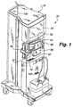
- the dialysis machine 30 includes an enclosure 32 to which are attached, or within which are housed, those functional devices and components of the dialysis machine 30 which are generally illustrated in Fig. 2.
- the enclosure 30 also includes a conventional input/output ("I/O") device for controlling the machine 30, such as a touch-screen monitor 33 as shown in Fig. 1.
- I/O input/output
- the dialysis machine 30 includes at least one blood pump 34 which controls the flow of blood from a patient 36.
- An arterial line or tubing 38 is connected through an arterial clamp 40 to a blood handling cartridge 42.
- the blood handling cartridge 42 is normally retained behind a door 44 (Fig. 1) of the machine 30 when used, thus the blood handling cartridge 42 is not shown in Fig. 1.
- the blood pump 34 also is located behind the door 44 adjacent to the cartridge 42.
- the blood pump 34 in dialysis machines is typically a peristaltic pump.
- Blood from the patient 36 flows through an extracorporeal circuit when the arterial clamp 40 is open and the blood pump 34 draws blood from the patient 36.
- the blood passes through the arterial line 38 and into an arterial reservoir 46 of the cartridge 42.
- the blood pump 34 draws blood from the arterial reservoir 46 through a pump header 48 which is squeezed or pinched by a rotating rotor 49 against a stationary raceway 50, in the typical manner of peristaltic pumps.
- the blood within the pump header 48 which is rotationally in front of the rotor 49 is propelled through the pump header 48 and into a manifold 51 of the cartridge 42.
- a tubing 52 conducts the blood from the manifold 51 of the cartridge 42 into a blood inlet 53 of a conventional dialyzer 54.
- a micro-porous membrane or other type of dialysis medium 56 divides the interior of the dialyzer 54 into a blood chamber 58 and a dialysate chamber 60.
- the dialyzer 54 As the patient's blood passes through the dialyzer 54, the waste products within the blood pass through the medium 56 where they mix with the dialysate in the chamber 60.
- the cleansed blood then exits the dialyzer 54 through a blood outlet 61 and is then transferred through a tubing 62 to an inlet 63 of a venous reservoir 64 of the cartridge 42. Any air which might have been unintentionally introduced into the blood is collected and removed while the blood is in the venous reservoir 64.
- a venous blood pump similar to the arterial blood pump 34 may be located along the venous line 66 to assist in returning the blood to the patient 36. If employed, the venous blood pump is positioned behind a second door 68 as shown in Fig.1.
- the blood flows through the venous line 66 to an air detector 70.
- the air detector 70 derives signals related to the quantity of air, if any, remaining in the venous line 66. If an excessive or dangerous amount of air is present, a venous line clamp 72 will immediately close and the blood pump 34 will stop to terminate the flow of blood through the venous line 66 before the detected air reaches the patient 36.
- the enclosure 32 of the dialysis machine 30 also encloses the various elements of a dialysate flow path, shown in abbreviated form in Fig. 2.
- the elements of the dialysate flow path include a number of different valves (most of which are not shown) and a dialysate pump 74 which draws dialysate from a container or from an internal supply 76 of dialysate which the dialysis machine 30 has prepared from appropriate chemicals and a supply of purified water.
- the dialysate pump 74 draws the dialysate from the supply 76 and delivers the dialysate through a dialysate supply tubing or line 78 to an inlet 79 of the dialysate chamber 60 of the dialyzer 54.
- the dialysate flows past the medium 56 where it absorbs the waste products from the blood in the blood chamber 58. Any beneficial components within the dialysate which are desired to be transferred to the blood pass through the medium 56 and enter the blood in the blood chamber 58.
- Dialysate containing the waste products exits the dialysate chamber 60 through an outlet 81 and is removed from the dialyzer 54 through a dialysate waste tubing or line 82 by operation of a drain pump 84.
- the drain pump 84 may be operated at a lesser volumetric pumping rate compared to the volumetric pumping rate of the dialysate pump 74 when it is desired to transfer components from the dialysate into the blood by fluid transport within the dialyzer 54.
- the drain pump 84 is operated at a greater volumetric pumping rate compared to the volumetric pumping rate of the dialysate pump 74 when it is desired to remove fluid components from the blood by fluid transport. Both of these flow control techniques are known as ultrafiltration and are well known dialysis treatments.
- the dialysate removed from the dialyzer 54 is delivered through the waste tubing 82 to a waste drain 86.
- the waste drain 86 may be a separate container which receives the used dialysate and accumulated waste products, or it may simply be a drain to a public sewer.
- the various valves and pumps which control the dialysate flow path are referred to generally as the dialysate hydraulics.
- an anticoagulant such as heparin into the extracorporeal flow path.
- the typical approach to injecting the anticoagulant is to slowly deliver it from a syringe 89.
- a plunger 90 of the syringe is slowly and controllably displaced into the syringe 89 by a linear driver mechanism (not shown), which is typically referred to as the anticoagulant pump.
- Anticoagulant from the syringe 89 is introduced into the manifold 51 of the cartridge 42 through a tubing 92 connected to the syringe as shown in Fig. 2.
- the anticoagulant pump is controlled to deliver the desired amount of anticoagulant during the dialysis treatment by the degree to which the anticoagulant pump moves the plunger 90 into the syringe 89 over a given time period.
- Tubings 94 and 96 are respectively connected to the arterial reservoir 46 and venous reservoir 64 of the cartridge 42 as shown in Fig. 2. Clamps or caps (not shown) are connected to the ends of the tubings 94 and 96 to selectively vent accumulated air from the reservoirs 46 and 64.
- a saline tubing 98 is also connected to the arterial reservoir 46 so that saline may be directly administered to the patient during treatment in case of low blood pressure.
- a pole 100 for supporting a conventional saline bag is attached to a side of the enclosure 32, as shown in Fig. 1. Additionally, medicines or other additives may be introduced into the blood through the access tubing 94 during treatment.
- the reservoirs 46 and 64 and the manifold 51 of the blood handling cartridge 42, together with the tubes 38, 48, 52, 62 and 66, are collectively referred to as a blood tubing set ("BTS").
- BTS blood tubing set
- the BTS is disposable and is typically discarded after each dialysis treatment.
- the dialyzer 54 is termed a disposable product, although it is not uncommon for a dialyzer to be reused with a single patient. A dialyzer will typically be reused by a patient who regularly visits the same clinic for dialysis treatments. Following each treatment, the dialyzer is cleaned with a sterilant and is then stored until the patient's next visit to the clinic. The dialyzer must then be thoroughly cleaned before use to ensure that the sterilant is not transferred to the patient's bloodstream during the next dialysis treatment.
- the disposable BTS and the dialyzer 54 (regardless of whether the dialyzer is new or "used") must be attached to a dialysis machine 30 and prepared for a patient's use by an operator. While the disposable BTS is sterile and thus does not need to be cleaned, the BTS and the dialyzer 54 must be primed with a sterile saline solution to remove the air from the extracorporeal circuit. In addition to flushing the dialyzer 54 with saline solution during priming, the saline solution must be recirculated through the dialyzer for a predetermined period of time to ensure that substantially all of the sterilant or other chemical debris within the dialyzer has been removed.
- This recirculation process also establishes a stable flow within the extracorporeal circuit and ensures that any remaining air within the circuit has been removed before the patient is connected to the machine 30.
- the arterial line 38 is attached to the patient and the patient's blood is drawn through the circuit.
- the venous line 66 is connected to the waste drain 86 to dispose of the used saline solution and, at the point the patient's blood has displaced all the saline within the circuit, the venous line is connected to the patient, as shown in Fig. 2.
- the automatic nature of the present invention allows a dialysis machine operator to attach the BTS and the dialyzer 54 to the dialysis machine 30 and make a small number of other connections to the BTS prior to commanding the machine 30 to perform both the priming and the recirculation procedures discussed above. Upon the conclusion of the recirculation procedure, the machine 30 will place itself in a steady state mode and provide an indication that it is ready for connection to a patient.
- the BTS includes a Y- or T-shaped connector 102 (Fig. 8) which is adapted to commonly connect the ends of the arterial line 38 and the venous line 66 to a waste line 104 which, in turn, is connected to the waste basin or drain 86.
- the waste line 104 is considered to be separate from the waste tubing 82 (Fig. 2) leading from the outlet 81 of the dialyzer 54, although one skilled in the art could utilize a single waste tubing for both purposes.
- a waste valve 106 is used to selectively open and close the waste line 104.
- valve 106 When the valve 106 is open, fluid within the Y-shaped connector 102 is directed to the waste drain 86. However, the valve 106 may be closed to effectively connect the arterial line 38 to the venous line 66 through the Y connector 102 when the arterial and venous clamps 40 and 72 are open.
- the waste valve 106 may be internal to the dialysis machine 30 so that an external waste handling port 107 may be used to connect the connector 102 to the waste drain 86. Details of such a waste handling port for use on a dialysis machine may be found in U.S. Patent 5,041,215, entitled Dialysis Unit Priming and assigned to the assignee hereof.
- a male portion 112 of the Y-shaped connector 102 is inserted directly within the port 107.
- the waste line 104 is connected to a bottom end of the port 107 and passes through the waste valve 106 (not shown in Fig. 8) which is internal to the dialysis machine enclosure 32.
- the port 107 preferably defines a relatively large gap 114 between the male portion 112 of the connector 102 and the waste line 104 to provide a sterile "air barrier" between the Y-shaped connector 102 and fluid within the waste line 104.
- the remaining two ends 116 and 118 of the Y-shaped connector 102 preferably include male Luer connectors for connection to the arterial and venous lines 38 and 66, respectively.
- the Y-shaped connector 102 is preferably pre-attached to the arterial and venous lines 38 and 66 as shown in Fig. 8 (and may be pre-attached to the waste line 104 when the external waste valve 106 is used as shown in Figs. 3-7), the Y-shaped connector may be packaged separately for attachment to blood tubing sets which do not include a Y-shaped connector. Additionally, while the waste port 107 and the internal waste valve 106 are preferably used as shown in Fig. 8, the waste valve 106 is illustrated with the waste drain 86 on the exterior of the dialysis machine in Figs. 3-7 for the sake of clarity in describing the remainder of the invention.
- the operator Before the start of the priming process, the operator must attach the BTS (including the Y-shaped connector 102 and the attached waste line 104) and the dialyzer 54 to the dialysis machine 30 as shown in Fig. 1.
- the pump header 48 (Fig. 2) is placed about the pump rotor 49 and the tubings 52 and 62 are connected to the dialyzer 54, as shown in Fig. 3.
- the operator must pass the lines 38 and 66 through their respective clamps 40 and 72, and connect the waste line 104 through the waste valve 106 to the waste drain 86.
- the operator After connecting the various lines as shown in Fig. 3 and ensuring that the clamps 40 and 72 are closed, the operator must hang a bag 108 of sterilized saline from the pole 100 (Fig. 1) and, after spiking the bag, connect a line 110 from the bag 108 to the saline tubing 98 on the arterial reservoir 46. The operator then opens the cap on the tubing 94 leading from the arterial reservoir 46, thus allowing saline from the bag 108 to gravity fill the arterial reservoir 46 as air within the reservoir 46 escapes through the tubing 94. Once the arterial reservoir 46 is mostly filled with saline (Fig. 3), the operator closes the cap on the tubing 94. The dialysis machine 30 is now set for priming and recirculation, and the operator's sole remaining task is to select the automatic prime and recirculate function from the touch screen 33 (Fig. 1).
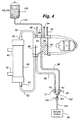
- the dialysis machine initiates the priming procedure, as shown in Fig. 4, by opening the arterial clamp 40 and the waste valve 106, thereby allowing the saline within the arterial reservoir 46 to flush the air out of the arterial line 38 before it is disposed of down the waste drain 86.
- the saline within the arterial reservoir 46 is replenished from saline within the bag 108, and the machine 30 closes the arterial clamp 40 after a predetermined time period to preserve the sterile saline solution within the bag 108.
- the predetermined time is sufficient to clear the air from the arterial line 38.
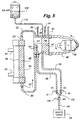
- the machine 30 immediately initiates the next step in the automatic priming process, as shown in Fig. 5, by closing the arterial clamp 40 and opening the venous clamp 72.
- the machine then commands the pump rotor 49 to turn in a forward direction to fill the remainder of the extracorporeal circuit (the BTS and the dialyzer 54) with saline from the bag 108.
- the saline passes through the pump header 48, the manifold 51, the tubing 52, the dialyzer 54 and the tubing 62 before entering the venous reservoir 64.
- the saline then drains from the outlet 65 (Fig. 2) of the venous reservoir and through the venous line 66 (past the open venous clamp 72) and the Y-shaped connector 102 to the waste drain 86.
- additional saline is drawn from the bag 108 to maintain saline level within the arterial reservoir 46.
- Priming the circuit in this manner serves to either flush a new dialyzer 54 (as is typically recommended by dialyzer manufacturers) or to cleanse a majority of the sterilant from a reused dialyzer. Additionally, a majority of the air within the BTS and the dialyzer 54 is expelled with the saline (and any sterilant flushed from the dialyzer) down the waste drain 86. However, some air will remain trapped within the dialyzer 54, and this trapped air typically floats to the top of the blood chamber 58 adjacent the inlet 53.
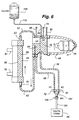
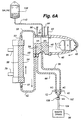
- the next step in the automatic priming sequence is to close the waste valve 106, open the arterial clamp 40, and run the blood pump rotor 49 backwards to push the saline solution backwards through the extracorporeal circuit.
- the fluid is pushed out of the arterial reservoir 46, through the Y-shaped connector 102, into the venous reservoir 64 and backward through the dialyzer 54 so that a portion of the air within the venous reservoir 64, together with the air trapped at the top of the dialyzer 54, is pushed out the inlet 53 and into the manifold 51.
- the entrained air bubbles are then forced by the pump 34 into the arterial reservoir 46 where they collect at the top of the reservoir.
- the increased air volume at the top of the reservoir reduces the level of saline in the arterial reservoir 46 while simultaneously preventing additional saline from entering the reservoir 46 through the saline tubing 98, as shown in Fig. 6A.
- the machine 30 automatically switches from the priming procedure to the recirculation procedure without the need to reconfigure any of the connections of the dialyzer, the saline bag or the BTS.
- the recirculation procedure as shown in Fig. 7, entails closing the waste valve 106, opening the arterial and venous clamps 40 and 72, and running the blood pump 34 forward while the machine 30 commands the hydraulics responsible for the dialysate flow path to pull a predetermined level of fluid from the dialyzer 54 across the medium 56.
- the recirculation process mimics the normal dialysis process while short circuiting the patient 36 by connecting the arterial and venous lines 38 and 66, respectively, through the Y-shaped connector 102.
- the machine 30 By commanding the dialysate hydraulics to pull a certain amount of fluid from the blood chamber 58 of the dialyzer 54, the machine 30 is essentially conducting ultrafiltration.
- the liquid pulled through the medium 56 comprises only the saline solution and any sterilant still remaining within the dialyzer 54 following the priming procedure.
- the recirculation process thus helps to ensure that a reused dialyzer is properly cleansed before it is connected to a patient.
- the machine 30 After a predetermined time during which the touch screen monitor 33 (Fig. 1) may provide a count-down timer to display the time remaining for recirculation, the machine 30 notifies the operator via an audible signal (in conjunction with an indication on the touch screen monitor 33) that the recirculation process has been completed. Simultaneously, the machine commands the dialysate hydraulics to stop pulling fluid through the dialyzer medium 56 and simply allows the pump to continue recirculating the saline through the extracorporeal circuit. By halting the "ultrafiltration" process, the machine 30 conserves the saline that must be drawn from the bag 108 to replenish the fluid pulled from the dialyzer.
- the machine continues to recirculate the saline within the circuit until the patient is ready to be connected to the machine. In addition to maintaining an established flow, the continued recirculation helps to dilute any potential pockets of sterilant remaining within the dialyzer.
- the operator thus knows when the machine 30 has finished both the priming and the recirculation procedures. The operator further knows that if the patient is delayed, the machine will continue its beneficial recirculation function while not wasting any saline once the machine has halted the ultrafiltration process.
- the clinic can thus set its parameters, including the predetermined times and fluid volumes used for each step of the priming and recirculating process, so that a sufficient level of saline remains within the bag 108 for use during the dialysis treatment.
- the saline bag 108 is left attached to the saline tube 98 of the arterial reservoir 46 during patient treatment.
- the saline line 110 will normally be clamped during the dialysis treatment, the line 110 may be opened in case the patient experiences low blood pressure and requires an influx of fluid.
- the operator needs only to clamp the lines 94 and 110 and disconnect the arterial line 38 from the Y-shaped connector 102.
- a leashed cap 120 on the Y-shaped connector is placed over the end 116 to prevent saline within the BTS from spilling out of the Y-shaped connector 102 once the arterial line 38 is disconnected.
- the arterial line 38 is then attached to the patient 36, as shown in Fig. 2.
- the venous line 66 remains connected to the waste drain 86 through the Y-shaped connector 102 to dispose of the recirculated saline.
- the venous line is disconnected from the end 118 of the Y-shaped connector 102 and attached to the patient as shown in Fig. 2.
- the disposable Y-shaped connector 102 may then be discarded. The dialysis treatment thus progresses in a normal fashion from this point.
- the different steps of the automatic priming and recirculating process require that the various clamps be opened and closed at specific predetermined times and that the pump rotor 49 be run in various directions and at various speeds for predetermined durations.
- a microprocessor (not shown) within the enclosure 32 is programmed to operate the clamps and pumps as described above to perform both the priming and the recirculation procedures.
- the different hospitals and clinics using the dialysis machine 30 need only program the microprocessor with the different predetermined times and durations (and their corresponding fluid volumes) according to a specific set of parameters previously established by the hospital or clinic.
- the machine 30 may be programmed to open the arterial clamp 40 for 7 seconds to flush the arterial line 38 with the saline stored in the arterial reservoir 46.
- the clinic may have previously determined through testing that the 7 second period is sufficient to completely flush the air out of the arterial line 38, and that leaving the clamp 40 open for a longer period would only serve to waste the sterile saline solution.
- the clinic will typically establish a parameter for the amount of time the blood pump 34 is to run in the recirculation step shown in Fig. 7 before the dialysate hydraulics are commanded to stop pulling fluid through the dialyzer medium (e.g., 20 minutes).
- the lengths of the different steps may be varied with different types of dialyzers.
- variations on a particular step may be programmed into the machine 30 to account for changing variables.
- the step of priming the venous side of the circuit, including the dialyzer 54 can be altered when a new dialyzer is used.
- Dialyzer manufacturers typically require that a new dialyzer be flushed with saline for a longer period than a dialyzer which is being reused.
- the machine 30 is informed that a new dialyzer is being used, it can prolong the step shown in Fig. 5 to meet the manufacturer's requirements.
- a plate dialyzer is utilized in place of the more typical hollow fiber dialyzers illustrated in Figs.
- the dialyzer manufacturer typically suggests that the dialyzer be subjected to a high pressure flow during priming to expand the plates within the dialyzer (similar to blowing up a balloon). If the machine 30 is informed that a plate dialyzer is being used, it may alter the above-described step of resetting the fluid level in the venous reservoir 64 by closing the venous clamp 72 for a longer period of time and allowing the pressure within the dialyzer to rise to a greater level before popping open the venous clamp 72.
- the significant contribution of the present invention is that a clinic or hospital may be certain that their established parameters for setting up a dialysis machine are being precisely followed with no possibility of human error or distraction.
- the machine 30 may be programmed for different contingencies, such as using different types of dialyzers.
- the greatest benefit of the present invention is that it allows busy nurses or dialysis operators the freedom to direct their attention elsewhere while the dialysis machine automatically cycles through the various steps of the priming and the recirculation procedures. The operator no longer has to revisit a dialysis machine and change the configuration of the blood tubing set over the course of the machine set-up.
- the operator is only required to make a limited number of connections before starting the procedure and then, after informing the machine of all the potential variable parameters (i.e., the type of dialyzer used), command the machine to start the procedure.
- the operator can then turn his or her attention to other patients or other machines requiring set up, comfortable in the knowledge that the dialysis machine will complete the priming and recirculation procedures according to the preestablished parameters and then notify the operator when it is ready to be connected to a patient.
- the present invention can save a great deal of operator time, while simultaneously ensuring that each machine is being set up in a manner consistent with the clinic's established parameters.
- the labor savings associated with the present invention together with the savings realized from using an optimum amount of saline during the priming and recirculation procedures, translates to a notable monetary savings to hospitals and dialysis clinics.
- the technique of the present invention relates both to the novel method of priming and recirculating a dialysis machine and the unique apparatus which enables the machine to carry out the new method.
- This apparatus includes the waste valve 106 (not previously used on dialysis machines) and the Y-shaped connector 102 (not previously included with conventional blood tubing sets). Additionally, while a preferred embodiment of the present invention is illustrated with a double-needle dialysis treatment (i.e., using a single pump 34 to draw and return blood to the patient at two separate locations as shown in Fig.
- the present invention could be utilized with existing dialysis machines once they have been fitted with the waste valve 106 (and appropriate microprocessor software for controlling the blood pump and the valves), in addition to the arterial clamp 40 if the machine does not already include an arterial clamp (as is common with some single pump dialysis machines). Additionally, conventional blood tubing sets must be modified to include the Y-shaped connector 102. Thus, the present invention may be utilized with both new and existing dialysis machines which include the above-described apparatus.
Landscapes
- Health & Medical Sciences (AREA)
- Heart & Thoracic Surgery (AREA)
- Vascular Medicine (AREA)
- Biomedical Technology (AREA)
- Engineering & Computer Science (AREA)
- Anesthesiology (AREA)
- Cardiology (AREA)
- Hematology (AREA)
- Life Sciences & Earth Sciences (AREA)
- Animal Behavior & Ethology (AREA)
- General Health & Medical Sciences (AREA)
- Public Health (AREA)
- Veterinary Medicine (AREA)
- External Artificial Organs (AREA)
Claims (28)
- Verfahren zum Vorfüllen einer Dialysemaschine (30), die einen Dialysator (54), eine Pumpe (34) und einen Blutschlauchsatz, der eine arterielle Leitung (38) zum Ansaugen von Blut von einem Patienten, einen Pumpenkopf (48) für die Pumpe zum Pumpen des Blutes zum Dialysator (54), eine venöse Leitung (66) zum Zurückleiten des durch den Dialysator (54) gepumpten Blutes zum Patienten und einen Verbinder (102) zum Verbinden der arteriellen Leitung und der venösen Leitung (38 und 66) enthält, besitzt, wobei das Verfahren die folgenden Schritte umfasst:Verbinden der arteriellen Leitung (38) und der venösen Leitung (66) mit dem Verbinder (102);Verbinden des Verbinders (102) mit einer Ablaufleitung (86);Schalten eines Ablaufventils (106) zwischen den Verbinder (102) und die Ablaufleitung (86);Befüllen der arteriellen Leitung (38) mit einer sterilen Lösung;Öffnen des Ablaufventils (106) und einer arteriellen Klemme (40) an der arteriellen Leitung (38), damit die sterile Lösung in der arteriellen Leitung (38) durch den Verbinder (102) abläuft und am offenen Ablaufventil (106) vorbei die Ablaufleitung (86) nach unten fließt;Schließen der arteriellen Klemme (40);Öffnen einer venösen Klemme (72) an der venösen Leitung (66) und Betreiben der Pumpe (34) in einer Vorwärtsrichtung, um sterile Lösung von der arteriellen Leitung (38) durch den Pumpenkopf und den Dialysator (54) anzusaugen und um der sterilen Lösung zu ermöglichen, durch die venöse Leitung (66) und den Verbinder (102) an dem offenen Ablaufventil (106) vorbei die Ablaufleitung (86) nach unten abzulaufen; undSchließen des Ablaufventils (106), Öffnen der arteriellen Klemme (40) und Betreiben der Pumpe (34), um die sterile Lösung durch den Dialysator (54) und den Blutschlauchsatz zurückzuleiten.
- Verfahren nach Anspruch 1, bei dem der Verbinder (102) drei Arme besitzt, wobei die Arme ein erster Arm für die Verbindung mit der arteriellen Leitung (38), ein zweiter Arm für die Verbindung mit der venösen Leitung (66) und ein dritter Arm für die Verbindung mit der Ablaufleitung (86) über das Ablaufventil sind.
- Verfahren nach Anspruch 1 oder 2, bei dem die Dialysemaschine (30) einen Mikroprozessor enthält, der so beschaffen ist, dass er die Pumpe (34), die arterielle Klemme (40), die venöse Klemme (72) und das Ablaufventil (106) automatisch betreiben kann, und bei dem:die Schritte, die dem Schritt des Schaltens eines Ablaufventils (106) zwischen den Verbinder (102) und die Ablaufleitung (86) folgen, durch die Dialysemaschine (30) automatisch ausgeführt werden.
- Verfahren nach Anspruch 1, 2 oder 3, das ferner den Schritt des direkten Ansaugens von Fluid von dem Dialysator (54) und des Entsorgens des Fluids während des Zurückleitens der sterilen Lösung durch den Dialysator (54) und den Blutschlauchsatz umfasst.
- Verfahren nach Anspruch 4, bei dem der Schritt des direkten Ansaugens von Fluid von dem Dialysator (54) zu einem vorgegebenen Zeitpunkt nach dem Beginn des Zurückleitens der sterilen Lösung durch den Dialysator (54) und den Blutschlauchsatz angehalten wird.
- Verfahren nach Anspruch 5, das ferner den Schritt des Erzeugens einer Angabe, dass die Dialysemaschine (30) zu einem Zeitpunkt, der dem vorgegebenen Zeitpunkt folgt, zu dem der Schritt des direkten Ansaugens von Fluid von dem Dialysator (54) angehalten wird, für die Verbindung mit dem Patienten bereit ist, umfasst.
- Verfahren nach einem der vorhergehenden Ansprüche, das ferner den Schritt umfasst, bei dem die sterile Lösung im Dialysator (54) und im Blutschlauchsatz nachgefüllt wird, wenn die sterile Lösung die Ablaufleitung (86) abwärts entsorgt worden ist.
- Verfahren nach Anspruch 4, 5 oder 6, das ferner den Schritt umfasst, bei dem die sterile Lösung im Dialysator (54) und im Blutschlauchsatz nachgefüllt wird, wenn die sterile Lösung entweder durch den Verbinder (102) abgeführt oder direkt vom Dialysator (54) angesaugt und die Ablaufleitung (86) abwärts entsorgt worden ist.
- Verfahren nach einem der vorhergehenden Ansprüche, bei dem das Zurückleiten der sterilen Lösung durch den Dialysator (54) und den Blutschlauchsatz solange fortgesetzt wird, bis die Dialysemaschine (30) mit dem Patienten verbunden ist.
- Verfahren nach einem der vorhergehenden Ansprüche, bei dem der Schritt des Betreibens der Pumpe (34) in einer Vorwärtsrichtung, um die sterile Lösung durch den Dialysator (54) und die Ablaufleitung (86) abwärts zu saugen, verlängert wird, wenn statt der erneuten Verwendung eines bereits verwendeten Dialysators ein neuer Dialysator in Verbindung mit dem Blutschlauchsatz verwendet wird.
- Verfahren nach einem der vorhergehenden Ansprüche, bei dem der Dialysator (54) ein Plattendialysator mit mehreren voneinander getrennten Platten ist, in dem benachbarte Blut- und Dialysat-Kanäle im Dialysator (54) definiert sind, das ferner die folgenden Schritte umfasst:Schließen der venösen Klemme (72) während des Schrittes des Zurückleitens der sterilen Lösung durch den Dialysator (54) und den Blutschlauchsatz, um den Fluiddruck im Dialysator (54) zu erhöhen und um die Platten im Dialysator (54) voneinander zu trennen; undÖffnen der venösen Klemme (72), um in dem Dialysator (54) und im Blutschlauchsatz einen Druckausgleich zu erzielen, nachdem die Platten im Plattendialysator (54) ausreichend weit getrennt worden sind.
- Verfahren nach einem der vorhergehenden Ansprüche, bei dem die Dialysemaschine (30) einen Mikroprozessor enthält, der so beschaffen ist, dass er die Pumpe (34), die arterielle Klemme (40), die venöse Klemme (72) und das Ablaufventil (106) automatisch betreibt, und bei dem:die Schritte, die dem Schritt des Befüllens der arteriellen Leitung (38) mit einer sterilen Lösung und des Öffnens des Ablaufventils (106) und der arteriellen Klemme (40) folgen, durch die Dialysemaschine (30) automatisch ausgeführt werden.
- Verfahren nach einem der vorhergehenden Ansprüche, bei dem:der Blutschlauchsatz einen venösen Vorratsbehälter (64) umfasst, um das von der arteriellen Leitung (38) durch den Dialysator (54) gepumpte Blut zu speichern;die venöse Leitung (66) so beschaffen ist, dass sie normalerweise das Blut von dem venösen Vorratsbehälter zum Patienten zurückleitet; undder Schritt des Öffnens einer venösen Klemme (72) an der venösen Leitung (66) und des Betreibens der Pumpe (34) in einer Vorwärtsrichtung sterile Lösung von der arteriellen Leitung (38) auch durch den venösen Vorratsbehälter saugt.
- Verfahren nach Anspruch 13, bei dem:der Blutschlauchsatz einen arteriellen Vorratsbehälter (46) umfasst, um das vom Patienten empfangene Blut zu speichern;der venöse Vorratsbehälter (64) außerdem so beschaffen ist, dass er das von dem arteriellen Vorratsbehälter (46) durch den Dialysator (54) gepumpte Blut speichert;der Schritt des Befüllens der arteriellen Leitung umfasst:ein erstes Schließen einer arteriellen Klemme (40) an der arteriellen Leitung (38), um zu verhindern, dass Fluid die arterielle Leitung (38) befüllt;Befüllen des arteriellen Vorratsbehälters (46) mit einer sterilen Lösung; undÖffnen der arteriellen Klemme (40), um die arterielle Leitung (38) mit der sterilen Lösung von dem arteriellen Vorratsbehälter (46) zu befüllen; undder Schritt des Öffnens einer venösen Klemme (72) an der venösen Leitung (66) und des Betreibens der Pumpe (34) in einer Vorwärtsrichtung die sterile Lösung auch von dem arteriellen Vorratsbehälter (46) durch den Dialysator (54) und den venösen Vorratsbehälter (64) saugt; und wobei das Verfahren ferner den folgenden Schritt umfasst:nach dem Schließen des Ablaufventils (106) und dem Öffnen der arteriellen Pumpe (40), jedoch vor dem Betreiben der Pumpe (34), um die sterile Lösung durch den Dialysator (54) und den Blutschlauchsatz zurückzuleiten, Betreiben der Pumpe (34) in Rückwärtsrichtung, um die sterile Lösung durch den Dialysator (54) und den Blutschlauchsatz rückwärts zu saugen.
- Verfahren nach den Ansprüchen 12 und 14, bei dem:die Schritte, die dem Schritt des Befüllens des arteriellen Vorratsbehälters (46) mit einer sterilen Lösung folgen, durch die Dialysemaschine (30) automatisch ausgeführt werden.
- Blutschlauchsatz für die Verwendung in einer Dialysebehandlung, die mit einer Dialysemaschine (30) ausgeführt wird, wobei der Blutschlauchsatz umfasst:eine arterielle Leitung (38), wovon ein Ende mit einer Blutpumpe (34) zu verbinden ist und wovon ein weiteres, gegenüberliegendes Ende während der Behandlung Blut von einem Patienten empfängt;eine venöse Leitung (66), wovon ein Ende mit einem Dialysator (54) zu verbinden ist, um durch den Dialysator (54) gepumptes Blut von der arteriellen Leitung (38) zu empfangen, und wovon ein weiteres, gegenüberliegendes Ende das Blut während der Behandlung zum Patienten zurückleiten kann; undeinen Verbinder (102), der vor der Ausführung der Behandlung zunächst mit den gegenüberliegenden Enden der arteriellen und der venösen Leitung (38 und 66) verbunden ist, wobei der Verbinder (102) einen internen Durchlass definiert, der die arterielle Leitung und die venöse Leitung (38 und 66) verbindet und miteinander kommunizieren lässt;einen Anschluss, der mit dem Verbinder kommuniziert und Fluid zu einer Ablaufleitung (86) leiten kann, bevor die Behandlung ausgeführt wird;eine Klemme (40) für die arterielle Leitung, um die arterielle Leitung (38) zu verschließen, so dass Fluid nicht von der arteriellen Leitung (38) zu der Ablaufleitung (86) strömen kann; undeine Klemme (72) für die venöse Leitung, um die venöse Leitung (66) zu verschließen, so dass Fluid nicht von der venösen Leitung (66) zu der Ablaufleitung (86) strömen kann.
- Blutschlauchsatz nach Anspruch 16, bei dem die gegenüberliegenden Enden der arteriellen Leitung und der venösen Leitung (38 und 66) von dem Verbinder (102), der während der Dialysebehandlung mit dem Patienten zu verbinden ist, getrennt werden können.
- Blutschlauchsatz nach Anspruch 16 oder 17, der ferner umfasst:einen Ablaufschlauch (104), der mit dem Anschluss des Verbinders (102) verbunden ist und sich zu einem Ablaufventil (106) der Dialysemaschine (30) erstrecken kann.
- Blutschlauchsatz nach Anspruch 18, bei dem der Ablaufschlauch (104) durch das Ablaufventil (106) geschlossen werden kann, um die Strömung von Fluid durch den Ablaufschlauch (104) anzuhalten.
- Blutschlauchsatz nach Anspruch 19, bei dem:der Anschluss die arterielle Leitung (38) und die venöse Leitung (66) mit dem Ablaufventil (106) verbindet, damit ein Fluid in der arteriellen Leitung (38) und in der venösen Leitung (66) durch die Ablaufleitung (86) ablaufen kann, wenn das Ablaufventil (106) geöffnet ist, und um Fluid zwischen der arteriellen Leitung und der venösen Leitung (38 und 66) durch den Verbinder (102) zu transportieren, wenn das Ablaufventil (106) geschlossen ist, wobei der Blutschlauchsatz einer Bedienungsperson erlaubt, die Dialysemaschine (30) auf einmal so zu konfigurieren, dass sie startet und eine sterile Lösung durch den Dialysator (54) und den Blutschlauchsatz zurückgeleitet wird, ohne dass die Dialysemaschine (30) nach dem Starten und vor dem Zurückleiten der sterilen Lösung umkonfiguriert werden muss.
- Blutschlauchsatz nach einem der Ansprüche 16 bis 20, bei dem die Strömung eines sterilen Fluids durch die arterielle Leitung und durch die venöse Leitung (38 und 66) und durch den Anschluss in die Ablaufleitung (86) den in Vorbereitung befindlichen Schlauchsatz für die Ausführung der Dialysebehandlung bereit macht und das Fehlen einer Strömung durch den Anschluss bewirkt, dass das sterile Fluid nach dem Starten und vor der Dialysebehandlung durch die arterielle Leitung und durch die venöse Leitung (38 und 66) zirkuliert.
- Blutschlauchsatz nach einem der Ansprüche 16 bis 21, bei dem der Verbinder (102), der beim Bereitmachen des Blutschlauchsatzes vor der Ausführung der Dialysebehandlung verwendet wird, umfasst:einen ersten Arm (116), der mit der arteriellen Leitung (38) verbunden ist; undeinen zweiten Arm (118), der mit der venösen Leitung (66) verbunden ist.
- Blutschlauchsatz nach Anspruch 22, der ferner umfasst:eine Kappe (120), um den ersten Arm abzudichten und um zu verhindern, dass Fluid im Verbinder (102) aus dem ersten Arm überläuft.
- Blutschlauchsatz nach Anspruch 23, bei dem die Kappe (120) an dem Verbinder (102) durch eine Schnur befestigt ist, um zu verhindern, dass die Kappe (120) verlorengeht, wenn die Kappe (120) den ersten Arm nicht abdichtet.
- Blutschlauchsatz nach einem der Ansprüche 16 bis 24, bei dem der Verbinder ein Y-förmiger Verbinder (102) ist, der umfasst:einen ersten Arm (116), der mit der arteriellen Leitung (38) verbunden werden kann;einen zweiten Arm (118), der mit der venösen Leitung (66) verbunden werden kann, wobei der erste Arm (116) und der zweite Arm (118) einen internen Durchlass definieren, um die arterielle Leitung und die venöse Leitung so zu verbinden, dass sie miteinander kommunizieren, sobald die arterielle Leitung und die venöse Leitung mit dem Verbinder (102) verbunden sind; undeinen Anschluss (112), der mit dem internen Durchlass kommuniziert und Fluid zu einer Ablaufleitung (86) leiten kann.
- Verbinder nach Anspruch 25, der ferner umfasst:eine Kappe (120), um den ersten Arm (116) abzudichten und um zu verhindern, dass Fluid im Verbinder (102) aus dem ersten Arm (116) ausläuft.
- Verbinder nach Anspruch 26, bei dem die Kappe an dem Verbinder durch eine Schnur befestigt ist, um zu verhindern, dass die Kappe verlorengeht, wenn die Kappe den ersten Arm nicht abdichtet.
- Dialysemaschine, die umfasst:eine Pumpe (34), einen Dialysator (54), eine Ablaufleitung (86), ein Ablaufventil (106), das an der Ablaufleitung (86) befestigt ist, und einen verbesserten Blutschlauchsatz nach einem der Ansprüche 16 bis 27.
Applications Claiming Priority (3)
| Application Number | Priority Date | Filing Date | Title |
|---|---|---|---|
| US481755 | 1995-06-07 | ||
| US08/481,755 US5650071A (en) | 1995-06-07 | 1995-06-07 | Technique for priming and recirculating fluid through a dialysis machine to prepare the machine for use |
| PCT/US1996/009231 WO1996040320A1 (en) | 1995-06-07 | 1996-06-06 | Technique for priming and recirculating fluid through a dialysis machine |
Publications (2)
| Publication Number | Publication Date |
|---|---|
| EP0831945A1 EP0831945A1 (de) | 1998-04-01 |
| EP0831945B1 true EP0831945B1 (de) | 2005-05-11 |
Family
ID=23913266
Family Applications (1)
| Application Number | Title | Priority Date | Filing Date |
|---|---|---|---|
| EP96917239A Expired - Lifetime EP0831945B1 (de) | 1995-06-07 | 1996-06-06 | Technik zum vorfüllen und rezirkulieren einer flüssigkeit in einer dialysemaschine |
Country Status (7)
| Country | Link |
|---|---|
| US (2) | US5650071A (de) |
| EP (1) | EP0831945B1 (de) |
| JP (2) | JP3951030B2 (de) |
| CA (1) | CA2219820C (de) |
| DE (1) | DE69634724T2 (de) |
| ES (1) | ES2238692T3 (de) |
| WO (1) | WO1996040320A1 (de) |
Cited By (2)
| Publication number | Priority date | Publication date | Assignee | Title |
|---|---|---|---|---|
| US8980094B2 (en) | 2006-05-11 | 2015-03-17 | Fresenius Medical Care Deutschland Gmbh | Method for filling and rinsing a set of blood lines |
| DE102016006090A1 (de) * | 2016-05-20 | 2017-11-23 | Fresenius Medical Care Deutschland Gmbh | Medizinische Vorrichtung mit zeitgesteuerter Startfunktion |
Families Citing this family (136)
| Publication number | Priority date | Publication date | Assignee | Title |
|---|---|---|---|---|
| US6066489A (en) | 1996-08-30 | 2000-05-23 | Arrow International, Inc. | Method for treating blood borne viral pathogens such as immunodeficiency virus |
| US7166084B2 (en) * | 1996-09-23 | 2007-01-23 | Dsu Medical Corporation | Blood set priming method and apparatus |
| US5895368A (en) * | 1996-09-23 | 1999-04-20 | Medisystems Technology Corporation | Blood set priming method and apparatus |
| US6387069B1 (en) | 1996-09-23 | 2002-05-14 | Dsu Medical Corporation | Blood set priming method and apparatus |
| US5951870A (en) * | 1997-10-21 | 1999-09-14 | Dsu Medical Corporation | Automatic priming of blood sets |
| US6187198B1 (en) | 1997-10-21 | 2001-02-13 | Dsu Medical Corporation | Automatic priming of connected blood sets |
| US5894011A (en) * | 1998-06-24 | 1999-04-13 | Prosl; Frank R. | Flow reversing device for hemodialysis |
| US6050278A (en) * | 1998-09-24 | 2000-04-18 | Minntech Corporation | Dialyzer precleaning system |
| US6027469A (en) * | 1998-12-03 | 2000-02-22 | Johnson; Lee D. | Disinfecting system for hemodialysis apparatus |
| BR9916408A (pt) * | 1998-12-22 | 2001-09-25 | Novoste Corp | Dispositivo de trasnferência que pode ser usado em um sistema para um tratamento intraluminal de um local selecionado em um corpo de um paciente |
| WO2000064510A1 (en) * | 1999-04-23 | 2000-11-02 | Nephros Therapeutics, Inc. | Extracorporeal circuit and related methods |
| US6491658B1 (en) * | 1999-06-29 | 2002-12-10 | Jms Co., Ltd. | Automated solution injection-discharge system and automated peritoneal dialysis system |
| US6526357B1 (en) | 1999-08-09 | 2003-02-25 | Gambro, Inc. | Associated parameter measuring and/or monitoring such as in the evaluation of pressure differences |
| IT1319785B1 (it) * | 2000-01-12 | 2003-11-03 | Gambro Dasco Spa | Metodo di svuotamento di un circuito ematico in una macchina didialisi e circuito ematico per l'attuazione del metodo. |
| DE10007327A1 (de) * | 2000-02-17 | 2001-08-30 | Fresenius Medical Care De Gmbh | Filtervorrichtung, vorzugsweise Hohlfaserdialysator mit gelockten Hohlfasern |
| US6308737B1 (en) | 2000-03-10 | 2001-10-30 | Transonic Systems, Inc. | Method and apparatus for selectively reversing flow between a dialyzer and a patient access |
| ITTO20010583A1 (it) * | 2001-06-15 | 2002-12-15 | Gambro Dasco Spa | Circuito di circolazione del sangue per una macchina di dialisi e relativa macchina di dialisi. |
| US6649063B2 (en) * | 2001-07-12 | 2003-11-18 | Nxstage Medical, Inc. | Method for performing renal replacement therapy including producing sterile replacement fluid in a renal replacement therapy unit |
| ITMI20020359A1 (it) * | 2002-02-22 | 2003-08-22 | Gambro Lundia Ab | Metodo di controllo dell'operativita' di un organo di interdizione del flusso e dispositivo di arresto del flusso per un circuito extracorpo |
| WO2004009156A2 (en) * | 2002-07-19 | 2004-01-29 | Baxter International Inc. | Systems and methods for peritoneal dialysis |
| MXPA05000817A (es) * | 2002-07-19 | 2005-04-28 | Baxter Int | Sistemas y metodos para realizar dialisis peritoneal. |
| EP1523350B1 (de) | 2002-07-19 | 2011-04-13 | Baxter International Inc. | System für die peritonealdialyse |
| US7998107B2 (en) * | 2002-09-24 | 2011-08-16 | Kensey Nash Corporation | Interventional procedure drive and control system |
| USD484982S1 (en) | 2002-09-27 | 2004-01-06 | Baxter International Inc. | Chassis for a medical machine |
| US8182440B2 (en) * | 2002-09-27 | 2012-05-22 | Baxter International Inc. | Dialysis machine having combination display and handle |
| USD483872S1 (en) | 2002-09-27 | 2003-12-16 | Baxter International Inc. | Display portion for a medical machine |
| USD492034S1 (en) | 2002-09-27 | 2004-06-22 | Baxter International Inc. | Base for a medical machine |
| US7351218B2 (en) * | 2002-12-20 | 2008-04-01 | Gambro Lundia Ab | Device and process for extracorporeal treatment by citrate anticoagulant |
| US7588722B2 (en) * | 2003-06-25 | 2009-09-15 | Gambro Lundia Ab | Extracorporeal treatment device with automatic emptying of waste bag |
| US7207733B2 (en) * | 2003-09-16 | 2007-04-24 | Academy Corporation | Photographic developer effluent transfer station and drain wash |
| US8029454B2 (en) | 2003-11-05 | 2011-10-04 | Baxter International Inc. | High convection home hemodialysis/hemofiltration and sorbent system |
| US8038639B2 (en) | 2004-11-04 | 2011-10-18 | Baxter International Inc. | Medical fluid system with flexible sheeting disposable unit |
| US7744553B2 (en) | 2003-12-16 | 2010-06-29 | Baxter International Inc. | Medical fluid therapy flow control systems and methods |
| CN2698358Y (zh) * | 2004-04-06 | 2005-05-11 | 上海江夏血液技术有限公司 | 血液过滤装置 |
| WO2006073166A1 (ja) * | 2005-01-07 | 2006-07-13 | Jms Co. | 自動プライミング方法 |
| US7842001B2 (en) * | 2005-01-07 | 2010-11-30 | Jms Co. | Automatic priming method |
| ITMO20050195A1 (it) * | 2005-07-29 | 2007-01-30 | Gambro Lundia Ab | Macchina per il trattamento extracorporeo di sangue |
| PL1924304T3 (pl) * | 2005-09-15 | 2011-05-31 | Gambro Lundia Ab | Sposób i urządzenie do napełniania i/lub płukania pozaustrojowego obiegu krwi |
| US8021319B2 (en) * | 2005-10-27 | 2011-09-20 | Gambro Lundia Ab | Extracorporeal blood set |
| US7559914B2 (en) * | 2005-12-14 | 2009-07-14 | Alcon, Inc. | Priming a microsurgical system |
| US7981280B2 (en) * | 2006-01-06 | 2011-07-19 | Renal Solutions, Inc. | Recirculation of blood in an extracorporeal blood treatment system |
| JP4613831B2 (ja) * | 2006-01-17 | 2011-01-19 | ニプロ株式会社 | 血液浄化装置及びその血液循環路の自動プライミング方法 |
| EP2724736B1 (de) | 2006-04-14 | 2022-06-08 | DEKA Products Limited Partnership | Kassette mit eingehauster pumpe |
| US10537671B2 (en) | 2006-04-14 | 2020-01-21 | Deka Products Limited Partnership | Automated control mechanisms in a hemodialysis apparatus |
| JP4783228B2 (ja) * | 2006-07-10 | 2011-09-28 | 東レ・メディカル株式会社 | 血液透析装置のプライミング方法および装置 |
| US20080021367A1 (en) * | 2006-07-18 | 2008-01-24 | Terumo Kabushiki Kaisha | Connector and blood line |
| DE102006061184A1 (de) * | 2006-12-22 | 2008-06-26 | Fresenius Medical Care Deutschland Gmbh | Verfahren zum Primen eines Blutschlauchsatzes |
| US8562834B2 (en) | 2007-02-27 | 2013-10-22 | Deka Products Limited Partnership | Modular assembly for a portable hemodialysis system |
| US8491184B2 (en) | 2007-02-27 | 2013-07-23 | Deka Products Limited Partnership | Sensor apparatus systems, devices and methods |
| US8357298B2 (en) | 2007-02-27 | 2013-01-22 | Deka Products Limited Partnership | Hemodialysis systems and methods |
| US8366655B2 (en) | 2007-02-27 | 2013-02-05 | Deka Products Limited Partnership | Peritoneal dialysis sensor apparatus systems, devices and methods |
| US9517295B2 (en) | 2007-02-27 | 2016-12-13 | Deka Products Limited Partnership | Blood treatment systems and methods |
| US20090107335A1 (en) | 2007-02-27 | 2009-04-30 | Deka Products Limited Partnership | Air trap for a medical infusion device |
| US8042563B2 (en) | 2007-02-27 | 2011-10-25 | Deka Products Limited Partnership | Cassette system integrated apparatus |
| US8425471B2 (en) | 2007-02-27 | 2013-04-23 | Deka Products Limited Partnership | Reagent supply for a hemodialysis system |
| US9028691B2 (en) | 2007-02-27 | 2015-05-12 | Deka Products Limited Partnership | Blood circuit assembly for a hemodialysis system |
| US8393690B2 (en) | 2007-02-27 | 2013-03-12 | Deka Products Limited Partnership | Enclosure for a portable hemodialysis system |
| CN101711171B (zh) | 2007-02-27 | 2014-03-26 | 德卡产品有限公司 | 血液透析系统及方法 |
| US8409441B2 (en) | 2007-02-27 | 2013-04-02 | Deka Products Limited Partnership | Blood treatment systems and methods |
| CN101678161B (zh) * | 2007-04-12 | 2012-11-07 | 甘布罗伦迪亚股份公司 | 用于对体外血液回路进行预充的方法和设备 |
| JP5031431B2 (ja) * | 2007-04-19 | 2012-09-19 | テルモ株式会社 | 体外循環回路 |
| US8764702B2 (en) * | 2007-07-05 | 2014-07-01 | Baxter International Inc. | Dialysis system having dual patient line connection and prime |
| US7892197B2 (en) | 2007-09-19 | 2011-02-22 | Fresenius Medical Care Holdings, Inc. | Automatic prime of an extracorporeal blood circuit |
| US8444587B2 (en) | 2007-10-01 | 2013-05-21 | Baxter International Inc. | Fluid and air handling in blood and dialysis circuits |
| US7892331B2 (en) * | 2007-10-01 | 2011-02-22 | Baxter International Inc. | Dialysis systems having air separation chambers with internal structures to enhance air removal |
| US7871462B2 (en) * | 2007-10-01 | 2011-01-18 | Baxter International Inc. | Dialysis systems having air separation chambers with internal structures to enhance air removal |
| US7892332B2 (en) * | 2007-10-01 | 2011-02-22 | Baxter International Inc. | Dialysis systems having air traps with internal structures to enhance air removal |
| US8771508B2 (en) | 2008-08-27 | 2014-07-08 | Deka Products Limited Partnership | Dialyzer cartridge mounting arrangement for a hemodialysis system |
| US8123947B2 (en) | 2007-10-22 | 2012-02-28 | Baxter International Inc. | Priming and air removal systems and methods for dialysis |
| US8114276B2 (en) | 2007-10-24 | 2012-02-14 | Baxter International Inc. | Personal hemodialysis system |
| JP4281835B2 (ja) * | 2007-11-06 | 2009-06-17 | 株式会社ジェイ・エム・エス | 血液透析装置 |
| US11833281B2 (en) | 2008-01-23 | 2023-12-05 | Deka Products Limited Partnership | Pump cassette and methods for use in medical treatment system using a plurality of fluid lines |
| US10201647B2 (en) | 2008-01-23 | 2019-02-12 | Deka Products Limited Partnership | Medical treatment system and methods using a plurality of fluid lines |
| EP2254616B1 (de) | 2008-01-23 | 2016-07-06 | DEKA Products Limited Partnership | Einwegflüssigkeitshandhabungs-kassette für peritonealdialyse |
| US20090294359A1 (en) * | 2008-06-03 | 2009-12-03 | Baxter International Inc. | Priming system and method using pumping and gravity |
| US8057679B2 (en) | 2008-07-09 | 2011-11-15 | Baxter International Inc. | Dialysis system having trending and alert generation |
| US8062513B2 (en) | 2008-07-09 | 2011-11-22 | Baxter International Inc. | Dialysis system and machine having therapy prescription recall |
| US20100051552A1 (en) | 2008-08-28 | 2010-03-04 | Baxter International Inc. | In-line sensors for dialysis applications |
| JP2013509271A (ja) | 2009-10-30 | 2013-03-14 | デカ・プロダクツ・リミテッド・パートナーシップ | 血管アクセスデバイスの離脱を検知するための装置および方法 |
| US9713670B2 (en) * | 2009-11-24 | 2017-07-25 | Fresenius Medical Care Deutschland Gmbh | Method for temporarily interrupting an extracorporeal blood treatment, control device and blood treatment apparatus |
| US8753515B2 (en) | 2009-12-05 | 2014-06-17 | Home Dialysis Plus, Ltd. | Dialysis system with ultrafiltration control |
| US8366649B2 (en) * | 2009-12-09 | 2013-02-05 | Araz Ibragimov | Manually operated disposable single-needle circuit for extracorporeal treatment of blood |
| US8501009B2 (en) | 2010-06-07 | 2013-08-06 | State Of Oregon Acting By And Through The State Board Of Higher Education On Behalf Of Oregon State University | Fluid purification system |
| DE102010032182B4 (de) * | 2010-07-23 | 2016-09-29 | Fresenius Medical Care Deutschland Gmbh | Spülleitung, medizintechnische Funktionseinrichtung, medizintechnische Behandlungsvorrichtung sowie Verfahren |
| ES2445592T3 (es) | 2010-12-20 | 2014-03-04 | Gambro Lundia Ab | Método y sistema para proporcionar líquidos de cebado y de restitución para un tratamiento de sangre extracorpóreo |
| JP5621591B2 (ja) * | 2010-12-29 | 2014-11-12 | ニプロ株式会社 | 血液浄化装置及びその血液循環路の自動プライミング方法 |
| US8382711B2 (en) | 2010-12-29 | 2013-02-26 | Baxter International Inc. | Intravenous pumping air management systems and methods |
| EP2688602B1 (de) | 2011-03-23 | 2019-11-06 | NxStage Medical, Inc. | Peritonealdialysesysteme, -vorrichtungen und -verfahren |
| CA3166031A1 (en) * | 2011-05-24 | 2012-11-29 | Deka Products Limited Partnership | Hemodialysis system |
| DE102011110472A1 (de) * | 2011-07-29 | 2013-01-31 | Fresenius Medical Care Deutschland Gmbh | Verfahren sowie Vorrichtungen zum Ablösen von Gasansammlungen von einem Gerinnselfänger eines extrakorporalen Blutkreislaufs |
| ES2640953T3 (es) | 2011-10-07 | 2017-11-07 | Outset Medical, Inc. | Purificación de líquido de intercambio de calor para un sistema de diálisis |
| US8951484B2 (en) * | 2012-01-31 | 2015-02-10 | The Regents Of The University Of Michigan | Circulating tumor cell capturing techniques and devices |
| EP2641624B1 (de) | 2012-03-21 | 2016-03-02 | Gambro Lundia AB | Lieferung einer Behandlungslösung in eine extrakorporale Blutbehandlungsvorrichtung |
| ES2534477T5 (es) † | 2012-05-09 | 2018-07-20 | D_Med Consulting Ag | Procedimiento para la cebadura de un dispositivo de hemodiálisis |
| US9364655B2 (en) | 2012-05-24 | 2016-06-14 | Deka Products Limited Partnership | Flexible tubing occlusion assembly |
| US9327066B2 (en) | 2013-03-13 | 2016-05-03 | Keith Samolyk | CPB system with dual function blood reservoir |
| US9452253B2 (en) * | 2013-03-13 | 2016-09-27 | Keith Samolyk | CPB system with fluid volume control |
| GB201305755D0 (en) * | 2013-03-28 | 2013-05-15 | Quanta Fluid Solutions Ltd | Re-Use of a Hemodialysis Cartridge |
| GB201314512D0 (en) | 2013-08-14 | 2013-09-25 | Quanta Fluid Solutions Ltd | Dual Haemodialysis and Haemodiafiltration blood treatment device |
| DE102014002650A1 (de) | 2014-02-27 | 2015-08-27 | Fresenius Medical Care Deutschland Gmbh | Schraubverbinder für medizinische Schlauchsysteme und medizinisches Schlauchsystem mit Schraubverbinder |
| DE102014002649A1 (de) * | 2014-02-27 | 2015-08-27 | Fresenius Medical Care Deutschland Gmbh | Schraubverbinder für medizinische Schlauchsysteme und medizinische Schlauchsysteme mit Schraubverbinder |
| JP6332605B2 (ja) * | 2014-02-27 | 2018-05-30 | 澁谷工業株式会社 | 血液透析装置の洗浄装置と洗浄方法 |
| EP3838308A1 (de) | 2014-04-29 | 2021-06-23 | Outset Medical, Inc. | Dialysesysteme und -verfahren |
| GB201409796D0 (en) | 2014-06-02 | 2014-07-16 | Quanta Fluid Solutions Ltd | Method of heat sanitization of a haemodialysis water circuit using a calculated dose |
| DE102014011671B4 (de) * | 2014-08-05 | 2023-12-28 | Fresenius Medical Care Deutschland Gmbh | Extrakoporale Blutbehandlungseinheit |
| DE102014113368A1 (de) * | 2014-09-17 | 2016-03-17 | B. Braun Avitum Ag | Dialysemaschine |
| US9486590B2 (en) | 2014-09-29 | 2016-11-08 | Fenwal, Inc. | Automatic purging of air from a fluid processing system |
| WO2016067946A1 (ja) * | 2014-10-31 | 2016-05-06 | 株式会社カネカ | 中空糸膜モジュールのプライミング方法 |
| WO2016164643A1 (en) * | 2015-04-07 | 2016-10-13 | Nxstage Medical, Inc. | Blood treatment device priming devices, methods, and systems |
| ES2987653T3 (es) | 2015-06-25 | 2024-11-15 | Gambro Lundia Ab | Sistema y método de dispositivo médico que tiene una base de datos distribuida |
| JP6246772B2 (ja) | 2015-10-06 | 2017-12-13 | 日機装株式会社 | 収納トレイ |
| GB201523104D0 (en) | 2015-12-30 | 2016-02-10 | Quanta Fluid Solutions Ltd | Dialysis machine |
| GB2547214A (en) | 2016-02-10 | 2017-08-16 | Quanta Fluid Solutions Ltd | Membrane pump usage condition detection |
| US10625009B2 (en) | 2016-02-17 | 2020-04-21 | Baxter International Inc. | Airtrap, system and method for removing microbubbles from a fluid stream |
| DE102016008755B4 (de) * | 2016-07-18 | 2024-06-06 | Fresenius Medical Care Deutschland Gmbh | Dialysegerät mit einer Steuereinheit zur Durchführung einer Konditionierung der Dialysemembran |
| JP7025408B2 (ja) | 2016-08-19 | 2022-02-24 | アウトセット・メディカル・インコーポレイテッド | 腹膜透析システム及び方法 |
| WO2018114346A1 (en) | 2016-12-21 | 2018-06-28 | Gambro Lundia Ab | Medical device system including information technology infrastructure having secure cluster domain supporting external domain |
| GB201622119D0 (en) | 2016-12-23 | 2017-02-08 | Quanta Dialysis Tech Ltd | Improved valve leak detection system |
| GB201701740D0 (en) | 2017-02-02 | 2017-03-22 | Quanta Dialysis Tech Ltd | Phased convective operation |
| GB201705273D0 (en) | 2017-03-31 | 2017-05-17 | Quanta Dialysis Tech Ltd | Data storage amd exchange by medical device components |
| JP6356872B2 (ja) * | 2017-05-29 | 2018-07-11 | 日機装株式会社 | 収納トレイ |
| WO2018237375A1 (en) | 2017-06-24 | 2018-12-27 | Nxstage Medical, Inc. | Peritoneal dialysis fluid preparation and/or treatment devices methods and systems |
| GB201710546D0 (en) | 2017-06-30 | 2017-08-16 | Quanta Dialysis Tech Ltd | Dialysis systems, devices and methods |
| USD907211S1 (en) | 2017-09-28 | 2021-01-05 | Quanta Dialysis Technologies Ltd. | Dialysis machine |
| US12226562B2 (en) * | 2017-10-31 | 2025-02-18 | Nextkidney Sa | Automated extracorporeal blood treatment apparatus |
| US20190262526A1 (en) * | 2018-02-28 | 2019-08-29 | Nxstage Medical, Inc. | Fluid Preparation and Treatment Devices Methods and Systems |
| US20190275217A1 (en) * | 2018-03-08 | 2019-09-12 | Fresenius Medical Care Holdings, Inc. | Devices for Securing Dialysis Fluid Lines and Related Systems and Methods |
| US10814057B2 (en) * | 2018-04-05 | 2020-10-27 | Baxter International Inc. | Disposable set for a gravity fed dialysis system |
| DE102018116071A1 (de) | 2018-07-03 | 2020-01-09 | B. Braun Avitum Ag | Verfahren zum automatisierten Primen eines extrakorporalen Blutleitungssystems sowie eine Vorrichtung hierfür |
| BR112021003168A2 (pt) | 2018-08-23 | 2021-05-11 | Outset Medical, Inc. | métodos para preparar um conjunto de tubos e um dialisador, para testar vazamentos, para preparar um conjunto de tubos, para melhorar a durabilidade e operação de uma ou mais bombas de deslocamento e para prover terapia de diálise, sistema de diálise, e, acessório de queima de bomba |
| WO2020073299A1 (en) * | 2018-10-12 | 2020-04-16 | Fresenius Medical Care Deutschland Gmbh | Priming method and priming apparatus |
| EP3962549B1 (de) | 2019-04-30 | 2025-11-05 | Outset Medical, Inc. | Dialysesystem |
| GB2584335A (en) | 2019-05-31 | 2020-12-02 | Quanta Dialysis Technologies Ltd | Source container connector |
| FR3107189B1 (fr) * | 2020-02-18 | 2024-01-19 | Physidia | Machine de dialyse et procede de rinçage |
| DE102020132472A1 (de) * | 2020-12-07 | 2022-06-09 | Fresenius Medical Care Deutschland Gmbh | Membrangasaustauscher |
| US20240165321A1 (en) * | 2022-11-19 | 2024-05-23 | Zaid Aljuboori | Degassed Infusion System for Arterial Infusion |
Citations (2)
| Publication number | Priority date | Publication date | Assignee | Title |
|---|---|---|---|---|
| US3944261A (en) * | 1975-03-05 | 1976-03-16 | Texas Medical Products, Inc. | Bifurcated tubing connector |
| DE3836399A1 (de) * | 1988-10-26 | 1990-05-03 | Schulz Lauterbach Achim | Rezirkulationsstueck fuer den patientenseitigen anschluss eines dialysators und verfahren zum reinigen und entlueften eines solchen dialysators |
Family Cites Families (9)
| Publication number | Priority date | Publication date | Assignee | Title |
|---|---|---|---|---|
| US4334988A (en) * | 1975-12-30 | 1982-06-15 | Hospal Medical Corp. | Control of dialysis and ultrafiltration |
| US4107039A (en) * | 1976-04-07 | 1978-08-15 | Extracorporeal Medical Systems, Inc. | Dialysate preparation system |
| US4209391A (en) * | 1978-11-06 | 1980-06-24 | Cordis Dow Corp. | Apparatus and method for automatically controlling hemodialysis at a pre-selected ultrafiltration rate |
| US4293413A (en) * | 1979-12-28 | 1981-10-06 | Baxter Travenol Laboratories, Inc. | Dialyzer blood circuit and bubble traps |
| DE8106491U1 (de) * | 1981-03-07 | 1981-10-15 | Schön, Hans-Günter, 7921 Nattheim | Infusionsbeutel |
| AU600711B2 (en) * | 1987-02-25 | 1990-08-23 | Baxter International Inc. | Purging system for a blood tubing network |
| US5041215A (en) * | 1989-11-22 | 1991-08-20 | Cobe Laboratories, Inc. | Dialysis unit priming |
| US5141493A (en) * | 1990-01-26 | 1992-08-25 | Sarcos Group | Peritoneal dialysis system |
| CA2092201A1 (en) * | 1990-08-20 | 1992-02-21 | Joaquin Mayoral | Medical drug formulation and delivery system |
-
1995
- 1995-06-07 US US08/481,755 patent/US5650071A/en not_active Expired - Lifetime
-
1996
- 1996-06-06 ES ES96917239T patent/ES2238692T3/es not_active Expired - Lifetime
- 1996-06-06 CA CA002219820A patent/CA2219820C/en not_active Expired - Lifetime
- 1996-06-06 WO PCT/US1996/009231 patent/WO1996040320A1/en not_active Ceased
- 1996-06-06 JP JP50160697A patent/JP3951030B2/ja not_active Expired - Lifetime
- 1996-06-06 EP EP96917239A patent/EP0831945B1/de not_active Expired - Lifetime
- 1996-06-06 DE DE69634724T patent/DE69634724T2/de not_active Expired - Lifetime
- 1996-10-22 US US08/735,366 patent/US5776091A/en not_active Expired - Lifetime
-
2006
- 2006-12-12 JP JP2006333948A patent/JP4427047B2/ja not_active Expired - Lifetime
Patent Citations (2)
| Publication number | Priority date | Publication date | Assignee | Title |
|---|---|---|---|---|
| US3944261A (en) * | 1975-03-05 | 1976-03-16 | Texas Medical Products, Inc. | Bifurcated tubing connector |
| DE3836399A1 (de) * | 1988-10-26 | 1990-05-03 | Schulz Lauterbach Achim | Rezirkulationsstueck fuer den patientenseitigen anschluss eines dialysators und verfahren zum reinigen und entlueften eines solchen dialysators |
Cited By (2)
| Publication number | Priority date | Publication date | Assignee | Title |
|---|---|---|---|---|
| US8980094B2 (en) | 2006-05-11 | 2015-03-17 | Fresenius Medical Care Deutschland Gmbh | Method for filling and rinsing a set of blood lines |
| DE102016006090A1 (de) * | 2016-05-20 | 2017-11-23 | Fresenius Medical Care Deutschland Gmbh | Medizinische Vorrichtung mit zeitgesteuerter Startfunktion |
Also Published As
| Publication number | Publication date |
|---|---|
| JP4427047B2 (ja) | 2010-03-03 |
| JP3951030B2 (ja) | 2007-08-01 |
| DE69634724D1 (de) | 2005-06-16 |
| CA2219820A1 (en) | 1996-12-19 |
| WO1996040320A1 (en) | 1996-12-19 |
| JPH11506962A (ja) | 1999-06-22 |
| US5650071A (en) | 1997-07-22 |
| DE69634724T2 (de) | 2006-01-12 |
| US5776091A (en) | 1998-07-07 |
| EP0831945A1 (de) | 1998-04-01 |
| JP2007105489A (ja) | 2007-04-26 |
| CA2219820C (en) | 2006-08-15 |
| ES2238692T3 (es) | 2005-09-01 |
Similar Documents
| Publication | Publication Date | Title |
|---|---|---|
| EP0831945B1 (de) | Technik zum vorfüllen und rezirkulieren einer flüssigkeit in einer dialysemaschine | |
| EP0830153B1 (de) | Technik zur desinfektion eines blutschlauchsystems unter gebrauch einer dialysemaschine | |
| EP2142234B1 (de) | Verfahren und gerät zum primen eines extrakorporalen blutkreislaufs | |
| JP5400617B2 (ja) | 血液チューブセットのプライミング方法 | |
| CN101443057B (zh) | 用于充注和冲洗血液管线组件的方法 | |
| JP2001520101A (ja) | 血液セットの自動注水 | |
| KR102579101B1 (ko) | 체외 혈액 치료 장치 | |
| JP2000107284A (ja) | 透析装置および洗浄プライミング方法 | |
| WO2003006139A1 (en) | Systems and methods for handling air and/or flushing fluids in a fluid circuit | |
| JP2021500094A (ja) | 透析機器および方法 | |
| US20080237128A1 (en) | Process and an Apparatus for Filling and/or Rinsing an Extracorporeal Blood Circuit | |
| JP3937436B2 (ja) | 血液浄化装置および血液回路の自動プライミング方法 | |
| JP4265466B2 (ja) | 血液浄化装置および血液回路の自動プライミング方法 | |
| US20230106599A1 (en) | Dialysis machine and method for rinsing same | |
| KR20220013375A (ko) | 체외 혈액 치료 후 혈액 회로 비우기 | |
| JP2006094934A (ja) | 血液浄化装置のプライミング方法および血液浄化装置 |
Legal Events
| Date | Code | Title | Description |
|---|---|---|---|
| PUAI | Public reference made under article 153(3) epc to a published international application that has entered the european phase |
Free format text: ORIGINAL CODE: 0009012 |
|
| 17P | Request for examination filed |
Effective date: 19971229 |
|
| AK | Designated contracting states |
Kind code of ref document: A1 Designated state(s): DE ES FR GB IT NL SE |
|
| RAP1 | Party data changed (applicant data changed or rights of an application transferred) |
Owner name: GAMBRO, INC., |
|
| 17Q | First examination report despatched |
Effective date: 20021001 |
|
| GRAP | Despatch of communication of intention to grant a patent |
Free format text: ORIGINAL CODE: EPIDOSNIGR1 |
|
| GRAS | Grant fee paid |
Free format text: ORIGINAL CODE: EPIDOSNIGR3 |
|
| GRAA | (expected) grant |
Free format text: ORIGINAL CODE: 0009210 |
|
| AK | Designated contracting states |
Kind code of ref document: B1 Designated state(s): DE ES FR GB IT NL SE |
|
| PG25 | Lapsed in a contracting state [announced via postgrant information from national office to epo] |
Ref country code: NL Free format text: LAPSE BECAUSE OF FAILURE TO SUBMIT A TRANSLATION OF THE DESCRIPTION OR TO PAY THE FEE WITHIN THE PRESCRIBED TIME-LIMIT Effective date: 20050511 |
|
| REG | Reference to a national code |
Ref country code: GB Ref legal event code: FG4D |
|
| REF | Corresponds to: |
Ref document number: 69634724 Country of ref document: DE Date of ref document: 20050616 Kind code of ref document: P |
|
| PG25 | Lapsed in a contracting state [announced via postgrant information from national office to epo] |
Ref country code: SE Free format text: LAPSE BECAUSE OF FAILURE TO SUBMIT A TRANSLATION OF THE DESCRIPTION OR TO PAY THE FEE WITHIN THE PRESCRIBED TIME-LIMIT Effective date: 20050811 |
|
| REG | Reference to a national code |
Ref country code: ES Ref legal event code: FG2A Ref document number: 2238692 Country of ref document: ES Kind code of ref document: T3 |
|
| NLV1 | Nl: lapsed or annulled due to failure to fulfill the requirements of art. 29p and 29m of the patents act | ||
| PLBE | No opposition filed within time limit |
Free format text: ORIGINAL CODE: 0009261 |
|
| STAA | Information on the status of an ep patent application or granted ep patent |
Free format text: STATUS: NO OPPOSITION FILED WITHIN TIME LIMIT |
|
| ET | Fr: translation filed | ||
| 26N | No opposition filed |
Effective date: 20060214 |
|
| REG | Reference to a national code |
Ref country code: GB Ref legal event code: 732E |
|
| REG | Reference to a national code |
Ref country code: GB Ref legal event code: 732E |
|
| REG | Reference to a national code |
Ref country code: FR Ref legal event code: TP |
|
| PGFP | Annual fee paid to national office [announced via postgrant information from national office to epo] |
Ref country code: ES Payment date: 20100628 Year of fee payment: 15 |
|
| REG | Reference to a national code |
Ref country code: ES Ref legal event code: FD2A Effective date: 20130405 |
|
| PG25 | Lapsed in a contracting state [announced via postgrant information from national office to epo] |
Ref country code: ES Free format text: LAPSE BECAUSE OF NON-PAYMENT OF DUE FEES Effective date: 20110607 |
|
| REG | Reference to a national code |
Ref country code: FR Ref legal event code: PLFP Year of fee payment: 20 |
|
| PGFP | Annual fee paid to national office [announced via postgrant information from national office to epo] |
Ref country code: GB Payment date: 20150526 Year of fee payment: 20 |
|
| PGFP | Annual fee paid to national office [announced via postgrant information from national office to epo] |
Ref country code: FR Payment date: 20150528 Year of fee payment: 20 Ref country code: IT Payment date: 20150611 Year of fee payment: 20 |
|
| PGFP | Annual fee paid to national office [announced via postgrant information from national office to epo] |
Ref country code: DE Payment date: 20150630 Year of fee payment: 20 |
|
| REG | Reference to a national code |
Ref country code: DE Ref legal event code: R071 Ref document number: 69634724 Country of ref document: DE |
|
| REG | Reference to a national code |
Ref country code: GB Ref legal event code: PE20 Expiry date: 20160605 |
|
| PG25 | Lapsed in a contracting state [announced via postgrant information from national office to epo] |
Ref country code: GB Free format text: LAPSE BECAUSE OF EXPIRATION OF PROTECTION Effective date: 20160605 |