EP0832033B1 - Strahlangetriebenes wasserfahrzeug - Google Patents
Strahlangetriebenes wasserfahrzeug Download PDFInfo
- Publication number
- EP0832033B1 EP0832033B1 EP96921840A EP96921840A EP0832033B1 EP 0832033 B1 EP0832033 B1 EP 0832033B1 EP 96921840 A EP96921840 A EP 96921840A EP 96921840 A EP96921840 A EP 96921840A EP 0832033 B1 EP0832033 B1 EP 0832033B1
- Authority
- EP
- European Patent Office
- Prior art keywords
- vehicle
- water
- floating
- nozzle
- channel
- Prior art date
- Legal status (The legal status is an assumption and is not a legal conclusion. Google has not performed a legal analysis and makes no representation as to the accuracy of the status listed.)
- Expired - Lifetime
Links
- XLYOFNOQVPJJNP-UHFFFAOYSA-N water Substances O XLYOFNOQVPJJNP-UHFFFAOYSA-N 0.000 title claims description 109
- 230000005484 gravity Effects 0.000 claims description 15
- 235000013361 beverage Nutrition 0.000 description 1
Images




Classifications
-
- B—PERFORMING OPERATIONS; TRANSPORTING
- B63—SHIPS OR OTHER WATERBORNE VESSELS; RELATED EQUIPMENT
- B63B—SHIPS OR OTHER WATERBORNE VESSELS; EQUIPMENT FOR SHIPPING
- B63B34/00—Vessels specially adapted for water sports or leisure; Body-supporting devices specially adapted for water sports or leisure
- B63B34/10—Power-driven personal watercraft, e.g. water scooters; Accessories therefor
Definitions
- the invention relates to a hydro-jet powered water vehicle having a jet motor and a seat for a passenger, said seat being provided with means for the feet of the passenger.
- the vehicle is robed so that when it does not carry any load, the floating center of the vehicle is located between the seat and one end of the vehicle and so that an open channel extends between the front end and the back end of the vehicle.
- Personal Motor Boats have generally one hull and have a floating center located between the front end of the boat and the passenger seat or seats. Such personal motor boats have never been provided with floating means defining an open channel extending between the front and back ends and having a vertical symmetrical plane.
- Jet-ski or watercrafts with a motorcycle-like configuration which are sold now-a-days by Bombardier or Kawasaki have only one hull in which no open channel are defined between the front and back ends. Furthermore, in these watercrafts, the people using it are standing or sitting on top of the motor for driving into rotation the turbine or between the said motor and the back end of the watercraft. The floating center of these watercrafts is adjacent to the front end thereof. The stability of these watercrafts is poor.
- the invention relates to a new kind of jet powered water vehicle allowing to reach very high speed, while having an increased stability at low speed, as well as at high speed.
- the water vehicle of the invention is adapted for carrying a load which is lower than a maximum predetermined load.
- Said vehicle comprises
- the water vehicle of the invention when it does not carry a load has a floating line and a floating center, such that the seat is located between, on the one hand, the vertical plane perpendicular to the symmetry plane and containing the center of gravity and, on the other hand, the vertical plane perpendicular to the symmetry plane and situated at the end of the floating means opposite to the end, in the vicinity of which the motor is attached.
- the motor is attached in the vicinity of the back end.
- the seat is attached to the floating means and is provided with means on which rest the feet of the passenger, said means and seat being constructived so that the seat is located between the front end and the motor and so that the means for the feet is located between the seat and the front end.
- the water vehicle when unloaded has then a floating center located between the seat and the back end, at most 50% of the being located under the floating line.
- the water vehicle of the invention when it carries the maximum predetermined load has such floating means that the cross section of the channel volume at the center of gravity, and perpendicular to the symmetry plane, is at least 5%, preferably 10% not immerged, i.e. above the floating line (open surface perpendicular to the floating line or plane).
- the floating means advantageously exert such a floating force that when the vehicle carries the maximum load, the water nozzle is substantially below the water level or floating line at a low forward speed, for example a speed lower to a first predetermined speed such as the minimum planing speed required so as to lift the vehicle provided with a minimum load above or substantially above the water.
- the floating means are also advantageously provided with planing means, so that at a speed higher than a second determined speed greater than the first determined speed, the floating means substantially plane above or on the water surface, while the water nozzle is above the water level.
- Said second determined speed is for example the minimum planing speed required so as to lift the vehicle with the maximum load above the water surface.
- the invention relates also to a water vehicle, the jet motor of which is provided with a means for acting on the water flow flowing through the nozzle so as to have a motion of the vehicle in a direction opposite to the direction of the water flow in the nozzle.
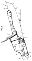
- the water vehicle shown in Figure 1 comprises the following elements :
- the hulls 1,2 have each a vertical face 11 extending between a front line 12, a back line 13, a lower line 14 and an upper line 15. Said two hulls 1,2 are separated the one from the other, so as to define between their vertical faces 11 an open channel 16 having a central vertical symmetry plane 17.
- the seat 8 is irritable so as to be located between the front end 3 and the motor 6, while the plate 9 between the front end 3 and the seat 8.
- the water vehicle when it does not carry a load, has a floating center located between the seat and the back end 4 (see Fig 6). Said center of gravity C1 is located in the vertical symmetry plane 17, just below the motor or adjacent to the motor.
- the hulls 1,2 of the water vehicle when it does not carry a load, have a front end 12 which is less immerged than the back end 13. Said front end 12 is even preferably not immerged in the water and is located above the water level.
- the lower lines 14 of the faces 11 of the hulls 1,2 are inclined, the angle of inclination A being of about 10-15° or even more.
- the lower line 14 has a part which is substantially linear, the end of said linear part adjacent to the back line 13 being under the floating line F1, while the opposite end of the linear part adjacent to the front line 12 is above the floating line F1.
- the channel 16 which is defined between the two vertical faces 11 of the vehicle without load has a cross section O1 extending in a plane perpendicular to the vertical symmetry plane 17, as well as to the floating line F1, and passing through the center of gravity C1 which is at most 50% immerged, for example 25% (75% of the part of the hulls 1,2 located in the plane in which extends the open surface O1 is above the water level).
- the channel 16 (see Figs 2 and 3) is open at its front end 3, at its back end 4, at its face 16a turned towards the bottom of the water surface (underneath face) and at its face 16b turned towards the sky (upper face).
- Said channel 16 has thus a front opening extending between the front lines 12 of the faces 11, a back opening extending between the back lines 13 of the faces 11, a bottom (underneath) opening 16a extending between the lower lines 14 of the faces and an upper opening 16b extending between the upper lines 15 of the faces.
- the open end of the nozzle 7 is preferably located within the channel 16, for example at a distance d of 5-15 (for example 10) cm from the back opening of the channel 16.
- the floating center C2 When the water vehicle carries the passenger (load), the floating center C2 is located between the floating center C1 of the vehicle without load and the front end 3.
- the linear part of the lower line 14 of the hulls 1,2 When the vehicle is not moving on a water surface, the linear part of the lower line 14 of the hulls 1,2 is under the water line F2.
- the hulls 1,2 are provided with planing means 18 so that when the water vehicle reaches a speed higher than a predetermined speed (minimum planing speed), the hulls 1,2 substantially plane above the water level. In this position, shown in figure 5, the water nozzle 7 is above the water level W. When said minimum planing speed is not reached, the open end of the nozzle 7 is under the water level or at least partly under the water level.
- the floating force exerted by the hulls is such that the open end of the nozzle is under the water level when the vehicle carries the maximum authorized load, while not moving, as well as when the vehicle does not carry any load (see Fig 6).
- the jet motor 6 is attached to a crossbeam 5 by means of a shaped plate 22 for cutting the water.
- the motor 6 comprises a turbine 23 for sucking water through an opening 24 and for expelling said water in the nozzle 7.
- the opening 24 extends below the underneath opening 16a of the channel defined between the two lower lines 14 of the faces 11. Said opening 24 extends advantageously just below said underneath opening 16a or in such a way that when the minimum planing speed is reached, the opening 24 still contacts the water and is below the water level.
- the jet motor 8 is provided with a means 25 which can be actuated between a first position (position shown in Fig 5) in which the means does not act on the water flow expelled through the nozzle 7 and a second position (position shown in Fig 3) in which the means acts on the water flow expelled through the nozzle 7, so as to reverse said flow.
- a means 25 acts on the water flow F
- the water flow F contacts the means 25 and is conducted to flow in a direction Y opposite to the direction of the water flow F in the nozzle 7.
- Said means is a flap with a curved face, said flap being mounted on a shaft 26 and being actuated by a control means for pivoting the flap between the said first and second positions.
- the planing means are located in the vicinity of the back end 13 of the hulls.
- said means are located between the vertical plane (O2) perpendicular to the median plane 17 and passing through the floating center C2 of the vehicle carrying the maximum authorized load, while not moving, and the back end 13.
- This planing means consist for example of planar parts 28 present on the underneath face 28 of the hulls 1,2.
- the said planar parts 28 of one hull substantially define a plane M forming an angle B of 70-85° with the median plane 17.
- the plane M of the underneath face 28 of the hull 1 intersects the plane M of the underneath face 28 of the hull 2 along a line extending into the median plane 17.
- the hulls are provided with a cavity suitable to receive personal equipment, food, beverage, ..., said cavity being closed by means of a cover 29.
- the water vehicle can be provided with an aileron 30 near the front end 3 and extending partly in the channel 16 (shown in broken lines).
- the part of the hulls 1,2 adjacent to the front end 12 is shaped so as cut the water and so as to lift the hulls.
- the nozzle 7 is mounted on a system provided with two shafts 30,31 whereby the direction of the flow F expelled out of the nozzle 7 can be modified.
- the bottom of the seat is about at the same level than the motor, when the vehicle carries the passenger.
- the floating means 1,2 are advantageouly the only floating means of the device.
- the device is not provided with supplementary floating elements, elements not acting as the major floating elements, i.e. elements representing less than 50%, preferably less than 25% of the global floating force or volume.
- the major floating elements i.e. the elements suitable for ensuring the floating of the major load, for example more than 75% or even more than 85% of the load
- the major floating elements are two floating elements located at or near the lateral side of the device.
- the motor 6 is located in the vicinity of the front end 3 of the vehicle.
- the water vehicle when unloaded has hulls 1,2, the front ends 12 of which are under the water level, while the back ends 13 of which are above the water level W.
- the seat 8 is located between the back end 4 and the vertical plane perpendicular to the symmetrical plane 17 of the channel 16 and containing the floating center C1.
- the channel cross section (vertical) O1 which is at least 5%, preferably at least 10%, above the water level.
- the channel When carrying the passenger, the channel has an open surface which is at least 5, preferably 10% above the water level (floating line).
- a hydro-jet powered water vehicle comprising two hulls provided with planing means so that, when a minimum forward speed is reached, the hulls substantially plane on the water surface, said vehicle being adapted for carrying at least one passenger with a load lower to a maximum authorized load, said vehicle when unloaded having an unloaded floating line and comprising at least one of the following features:
- the inclination of the lower end lines of the hulls with respect to the horizontal for the unloaded vehicle is comprised between 10-15°.
- the water vehicle when unloaded, has such a floating center that the seat is located between, on the one hand, the vertical plane perpendicular to the symmetry plane and passing through the center of gravity and, on the other hand, the front open end of the channel.
- the channel is then such that for the unloaded water vehicle at most 50% of the cross-section of the channel extending in a vertical plane perpendicular to the symmetry plane, and passing through the center of gravity is located under the unloaded floating line, and such that, for the vehicle carrying the maximum authorized load, the channel has a passage above the floating line from the front open end of the channel up to the back open end of the channel, for each cross-section of the channel perpendicular to the symmetry plane thereof, the minimum vertical surface of the said passage being at least 10% of the considered open vertical surface of the channel.
- the water vehicle may more particularly be provided with a seat attached to the floating means, the seat being located between the front open end of the channel and the motor, and in which the means for the feet is located between the seat and the front open end of the channel, the water vehicle when unloaded having a floating center located between the seat and the back open end of the channel.
- the seat has a bottom which is substantially at the level of the motor driving the turbine.
- the water nozzle of the motor when the vehicle carries the maximum authorized load an when the motor is not actuated, is below the floating line and at least 30% of the volume of the hulls are below the floating line, the channel being defined between two vertical parallel faces, extending each between a front line, a back line, a lower end line and an upper line, so as to form a front opening of the channel extending between the front lines, a back opening of the channel extending between the back lines, an underneath opening of the channel extending between the lower end lines and an upper opening of the channel extending between the upper lines.
Landscapes
- Chemical & Material Sciences (AREA)
- Engineering & Computer Science (AREA)
- Combustion & Propulsion (AREA)
- Mechanical Engineering (AREA)
- Ocean & Marine Engineering (AREA)
- Nozzles (AREA)
- Vehicle Cleaning, Maintenance, Repair, Refitting, And Outriggers (AREA)
- Aerodynamic Tests, Hydrodynamic Tests, Wind Tunnels, And Water Tanks (AREA)
- Agricultural Machines (AREA)
Claims (14)
- Wasserfahrzeug, das mit einem düsenartigen Hydroantrieb versehen ist und das dafür ausgestattet ist, eine Last unterhalb einer maximal zulässigen Last zu tragen, wobei das Fahrzeug in einem unbeladenen Zustand eine Schwimmlinie aufweist und mit folgenden Komponenten versehen ist:(a) Schwimmelemente (1, 2), die sich zwischen einem vorderen Ende (3) und einem hinteren Ende (4) erstrecken, wobei die Schwimmelemente derart angeordnet sind, daß ein offenes Kanalvolumen (16) zwischen dem vorderen Ende und dem hinteren Ende definiert ist, und wobei der Kanal eine vertikale Symmetrieebene aufweist, die sich zwischen dem vorderen Ende und dem hinteren Ende erstreckt;(b) ein düsenartiger Antrieb (6) mit einer Wasserdüse (7), wobei der Motor mit den Schwimmelementen (1, 2) in einer Umgebung eines Endes der Schwimmelemente verbunden ist;(c) mindestens ein Sitz (8) für einen Passagier, wobei der Sitz mit den Schwimmelementen (1, 2) verbunden ist und mit Mitteln (9) ausgestattet ist, auf welchen die Füße des Passagiers angeordnet werden können, und(d) Mitteln (10) zum Kontrollieren der Bewegung des Fahrzeuges:das Fahrzeug weist in einem unbeladenen Zustand einen Massenschwerpunkt C1 derart auf, daß der Sitz (8) eine Anordnung aufweist einerseits zwischen der vertikalen Ebene, die sich senkrecht zur Symmetrieebene (17) erstreckt und die den Massenschwerpunkt C1 beinhaltet, und andererseits zwischen einer vertikal verlaufenden und sich senkrecht zur Symmetrieebene (17) erstreckender Ebene, die an dem Ende der Schwimmelemente angeordnet ist, das gegenüberliegend zu dem Ende positioniert ist, in dessen Umgebung der Motor befestigt ist, wobei mindestens 50 % der Querschnittfläche des Kanalvolumens im Bereich des Massenschwerpunktes C1 sowie senkrecht zur Symmetrieebene (17) unterhalb der Schwimmlinie F1 liegt.
- Wasserfahrzeug nach Anspruch 1, wobei der düsenartige Antrieb (6) mit den Schwimmelementen (1, 2) in einer Umgebung des hinteren Endes (4) der Schwimmelemente befestigt ist, und wobei der Sitz (8) mit den Schwimmelementen (1, 2) verbunden und mit Mitteln (9) ausgestattet ist, auf welchen die Füße des Passagieres positioniert werden, wobei die Mittel und der Sitz derart angeordnet sind, daß der Sitz zwischen dem vorderen Ende (3) und dem Antrieb (6) positioniert ist, so daß die Mittel zur Positionierung der Füße zwischen dem Sitz und dem vorderen Ende angeordnet sind, und wobei das Wasserfahrzeug in einem unbeladenen Zustand einen Masseschwerpunkt C1 aufweist, der zwischen dem Sitz und dem hinteren Ende angeordnet ist, und wobei sich mindestens 50 % der Querschnittfläche des Kanalvolumens (16) im Bereich des Masseschwerpunktes C1 und senkrecht zur Symmetrieebene unterhalb der Schwimmlinie F1 erstreckt.
- Wasserfahrzeug nach Anspruch 2, wobei das Fahrzeug Schwimmelemente (1, 2) aufweist, die in einem Zustand, in dem das Fahrzeug eine maximal zulässige Last trägt, eine Schwimmlinie derart definieren, daß mindestens 10 % der Querschnittfläche des Kanalvolumens (16) im Masseschwerpunkt C1 sowie senkrecht zur Symmetrieebene oberhalb der Schwimmlinie F1 angeordnet ist.
- Wasserfahrzeug nach Anspruch 2, wobei das Fahrzeug Schwimmeelemente (1, 2) aufweist, die in einem Zustand, in dem das Fahrzeug eine maximal zulässige Last trägt, eine Schwimmlinie derart definieren, daß mindestens 10 % der Querschnittfläche des Kanalvolumens (16) im Masseschwerpunkt C1 sowie senkrecht zur Symmetrieebene oberhalb der Schwimmlinie angeordnet ist.
- Wasserfahrzeug nach mindestens einem der vorhergehenden Ansprüche, wobei die Schwimmelemente eine Auftriebskraft derart ausüben, daß in einem Zustand, in dem das Fahrzeug die maximal zulässige Last trägt, die Wasserdüse sich wenigstens im wesentlichen unterhalb des Wasserpegels für eine Vorwärtsgeschwindigkeit des Fahrzeuges erstreckt, die unterhalb einer ersten vorgegebenen Geschwindigkeit des Fahrzeuges ist, und bei der die Schwimmmittel mit Ausgleichselementen derart ausgestattet sind, daß bei einer Vorwärtsgeschwindigkeit des Fahrzeuges oberhalb einer zweiten vorgegebenen Geschwindigkeit, die größer als die erste vorgegebene Geschwindigkeit ist, die Schwimmelemente sich im wesentlichen plan auf der Wasseroberfläche erstrecken und daß die Wasserdüse oberhalb des Wasserpegels angeordnet ist.
- Wasserfahrzeug nach Anspruch 2, wobei die Schwimmmittel (1,2) eine Auftriebskraft derart ausüben, daß in einem Zustand, in dem das Fahrzeug eine maximale zulässige Last trägt, die Wasserdüse mindestens im wesentlichen unterhalb eines Wasserpegels für eine Vorwärtsgeschwindigkeit des Wasserfahrzeuges angeordnet ist, die geringer als eine erste vorgegebene Geschwindigkeit des Fahrzeuges ist, bei der die Schwimmelemente mit Ausgleichselementen (18, 28) derart ausgestattet ist, daß bei einer Vorwärtsgeschwingigkeit des Fahrzeuges oberhalb einer zweiten vorgegebenen Geschwindigkeit, die größer als die erste vorgegebene Geschwindigkeit ist, sich die Schwimmmittel im wesentlich plan auf der Wasseroberfläche erstrecken und daß die Wasserdüse (7) oberhalb des Wasserpegels angeordnet ist, und bei der bei einer Beladung mit einem maximal zulässigen Gewicht mindestens 5 % der offenen Oberfläche des Kanals zwischen dem vorderen Ende bis zum hinteren Ende oberhalb der Schwimmlinie angeordnet ist.
- Wasserfahrzeug nach Anspruch 2, wobei die Schwimmelemente (1, 2) eine Auftriebskraft derart ausüben, daß bei einer Beladung des Fahrzeuges mit einer maximal zulässigen Last die Wasserdüse (7) sich mindestens im wesentlichen unterhalb des Wasserpegels (W) für eine vorgegebene Geschwindigkeit des Fahrzeuges erstreckt, wobei die Geschwindigkeit geringer als eine erste vorgegebene Geschwindigkeit des Fahrzeuges ist, in der die Schwimmelemente mit Ausgleichselementen (18, 28) derart ausgestattet sind, daß bei einer Vorwärtsgeschwindigkeit des Fahrzeuges oberhalb einer zweiten vorgegebenen Geschwindigkeit oberhalb der ersten vorgegeben Geschwindigkeit sich die Schwimmelemente im wesentlichen plan auf der Wasseroberfläche erstrecken und daß die Wasserdüse (7) oberhalb der Wasseroberfläche angeordnet ist und daß sich bei einer Beladung des Fahrzeuges mit einer maximal zulässigen Last mindestens 10 % der offenen Oberfläche des Kanales im Bereich des vorderen Endes und des hinteren Endes oberhalb der Schwimmlinie erstreckt.
- Wasserfahrzeug nach Anspruch 2, wobei die Schwimmelemente (1, 2) derart angeordnet sind, daß diese einen Kanal (16) definieren, der sich mindestens bereichsweise zwischen zwei parallelen und vertikalen Seiten (11) erstreckt.
- Wasserfahrzeug nach Anspruch 8, wobei bei einer Beladung des Fahrzeuges mit einer maximal zulässigen Last und in einem ausgeschalteten Zustand des Antriebes (6) die Wasserdüse (7) des Antriebes sich unterhalb der Schwimmlinie erstreckt und daß mindestens 30 % des Volumens der Schwimmelemente (1, 2) unterhalb der Schwimmlinie angeordnet sind, wobei der Kanal (16) zwischen zwei Flächen definiert ist, die sich jeweils zwischen einer vorderen Linie, einer hinteren Linie, einer unteren Linie und einer oberen Linie erstrecken, so daß eine vordere Öffnung ausgebildet wird, die sich zwischen den vorderen Linien erstreckt, und wobei sich eine hintere Öffnung zwischen den hinteren Linien erstreckt sowie eine unten liegende Öffnung zwischen den unteren Linien und eine obere Öffnung zwischen den oberen Linien realisiert ist.
- Wasserfahrzeug nach Anspruch 2, wobei die Wasserdüse (7) des Antriebes (6) innerhalb des Kanales (16) in einer Umgebung des hinteren offenen Endes angeordnet ist.
- Wasserfahrzeug nach Anspruch 1, wobei die Wasserdüse (7) des Antriebes (6) in einer Entfernung zum offenen Endes des Kanales (16) angeordnet ist, die im Bereich zwischen 5 und 15 cm liegt.
- Wasserfahrzeug nach mindestens einem der vorhergehenden Ansprüche, wobei ein Querruder (30) im Bereich des vorderen Endes (3) des Kanales (16) angeordnet ist und wobei das Querruder oberhalb des Wasserpegels positioniert ist, wenn das Fahrzeug die maximal zulässige Last trägt.
- Wasserfahrzeug nach Wasserfahrzeug nach mindestens einem der vorhergehenden Ansprüche, wobei der düsenartige Antrieb (6, 7) mit Mitteln (25) zur Einwirkung auf die Wasserströmung ausgestattet ist, die durch die Düse einer Turbine fließt, um eine Bewegung des Fahrzeuges in eine der Richtung des Wasserflusses in der Düse entgegengesetzte Richtung hervorzurufen.
- Wasserfahrzeug nach Anspruch 13, wobei die Mittel zur Einwirkung auf die Wasserströmung als eine Klappe mit einer gekrümmten Oberfläche ausgebildet sind, wobei die Klappe mit Kontrollmitteln derart verbunden ist, daß diese zwischen einer Positionierung, in welcher die Klappe die Strömungsrichtung der Wasserströmung durch die Düse der Turbine hindurch nicht beeinflußt und einer Positionierung, in der die Klappe die Wasserströmung, die durch die Wasserdüse hindurch fließt, unter die Wasserdüse gerichtet wird, bewegbar ist.
Applications Claiming Priority (3)
| Application Number | Priority Date | Filing Date | Title |
|---|---|---|---|
| US495078 | 1995-06-27 | ||
| US08/495,078 US5567188A (en) | 1995-06-27 | 1995-06-27 | Jet powered water vehicle |
| PCT/BE1996/000070 WO1997001477A1 (en) | 1995-06-27 | 1996-06-26 | Jet powered water vehicle |
Publications (2)
| Publication Number | Publication Date |
|---|---|
| EP0832033A1 EP0832033A1 (de) | 1998-04-01 |
| EP0832033B1 true EP0832033B1 (de) | 1999-04-07 |
Family
ID=23967187
Family Applications (1)
| Application Number | Title | Priority Date | Filing Date |
|---|---|---|---|
| EP96921840A Expired - Lifetime EP0832033B1 (de) | 1995-06-27 | 1996-06-26 | Strahlangetriebenes wasserfahrzeug |
Country Status (6)
| Country | Link |
|---|---|
| US (1) | US5567188A (de) |
| EP (1) | EP0832033B1 (de) |
| CA (1) | CA2225730A1 (de) |
| DE (1) | DE69602021D1 (de) |
| ES (1) | ES2133194T3 (de) |
| WO (1) | WO1997001477A1 (de) |
Families Citing this family (8)
| Publication number | Priority date | Publication date | Assignee | Title |
|---|---|---|---|---|
| US6419532B1 (en) * | 2000-09-01 | 2002-07-16 | Edward Bradish, Jr. | Jet-propelled watercraft |
| FR2815011A1 (fr) | 2000-10-05 | 2002-04-12 | Sarl Oxoon | Engin nautique du type comprenant au moins une coque, muni d'un propulseur amovible |
| US6602103B1 (en) * | 2001-11-15 | 2003-08-05 | Steven R. Good | Float device |
| US6733349B2 (en) * | 2002-03-28 | 2004-05-11 | Andrew Chun | Jet propulsion boat |
| US7263945B2 (en) * | 2002-06-21 | 2007-09-04 | Little Rolland N | Pontoon for watercraft |
| US7220154B2 (en) * | 2003-11-13 | 2007-05-22 | Sword Marine Technology, Inc. | Outboard jet drive marine propulsion system |
| USD504921S1 (en) * | 2004-02-05 | 2005-05-10 | Nikko Electronics Bhd. | Remote control toy |
| USD900701S1 (en) * | 2017-10-05 | 2020-11-03 | Damien Leveille-Nizerolle | Watercraft |
Family Cites Families (8)
| Publication number | Priority date | Publication date | Assignee | Title |
|---|---|---|---|---|
| US2821948A (en) * | 1956-02-06 | 1958-02-04 | Ulysses S Harkson | Water craft having hydroplanes |
| US3145687A (en) * | 1962-04-26 | 1964-08-25 | Reley Corp | Jet type motor |
| US3964417A (en) * | 1974-05-14 | 1976-06-22 | Hydrobike Incorporated | Water vehicles |
| US4141309A (en) * | 1977-01-14 | 1979-02-27 | Halboth Robert V | Inboard powered watercraft |
| US4459117A (en) * | 1977-04-25 | 1984-07-10 | Jordan Robert L | Liquid jet propulsion |
| JPS591627B2 (ja) * | 1979-03-03 | 1984-01-13 | 正 岡嶋 | 有翼滑走艇 |
| FR2610280B1 (fr) * | 1987-01-30 | 1989-05-19 | Laboureau Jacques | Embarcation du type catamaran a propulsion mecanique |
| US5041040A (en) * | 1990-08-01 | 1991-08-20 | Jones Ronald O | Motorboat, without driver, controlled by water skier skiing, or optionally controlled by a driver |
-
1995
- 1995-06-27 US US08/495,078 patent/US5567188A/en not_active Expired - Fee Related
-
1996
- 1996-06-26 WO PCT/BE1996/000070 patent/WO1997001477A1/en not_active Ceased
- 1996-06-26 ES ES96921840T patent/ES2133194T3/es not_active Expired - Lifetime
- 1996-06-26 DE DE69602021T patent/DE69602021D1/de not_active Expired - Lifetime
- 1996-06-26 EP EP96921840A patent/EP0832033B1/de not_active Expired - Lifetime
- 1996-06-26 CA CA002225730A patent/CA2225730A1/en not_active Abandoned
Also Published As
| Publication number | Publication date |
|---|---|
| WO1997001477A1 (en) | 1997-01-16 |
| EP0832033A1 (de) | 1998-04-01 |
| ES2133194T3 (es) | 1999-09-01 |
| US5567188A (en) | 1996-10-22 |
| CA2225730A1 (en) | 1997-01-16 |
| DE69602021D1 (de) | 1999-05-12 |
Similar Documents
| Publication | Publication Date | Title |
|---|---|---|
| US5458078A (en) | High speed catamaran hull and boat | |
| US5647297A (en) | Foam stabilized watercraft | |
| US4813365A (en) | Double deadrise with multiple reflex chine boat hull structure and engine mounting system | |
| KR100415770B1 (ko) | 수면 항행기 | |
| AU779586B2 (en) | High speed surface effect ship hull configuration | |
| US5619944A (en) | Watercraft hull | |
| WO2003008262A2 (en) | Hull configuration utilizing multiple effects | |
| US5676087A (en) | Watercraft hull | |
| US20140373769A1 (en) | Watercraft hull | |
| US5567188A (en) | Jet powered water vehicle | |
| US6085677A (en) | No/low wake, high speed power catamaran hull | |
| US20040255836A1 (en) | Watercraft | |
| US20070017431A1 (en) | Watercraft | |
| US20040168623A1 (en) | Multi-hull personal watercraft | |
| US6872105B2 (en) | Watercraft having a jet propulsion system with improved efficiency | |
| US4883012A (en) | Dual-purpose water craft | |
| JPS643718B2 (de) | ||
| EP0249321A2 (de) | Schiffskörper | |
| EP0201326B1 (de) | Kleines Wasserfahrzeug | |
| JPS6116187A (ja) | 小型滑走艇 | |
| US20240425151A1 (en) | Personal watercraft | |
| RU2818372C1 (ru) | Быстроходное судно с импеллером для подвода сжатого воздуха под днище | |
| JPS62122897A (ja) | 小型ジエツト推進艇 | |
| JPH0717227B2 (ja) | 小型ジエツト推進艇 | |
| JP2726034B2 (ja) | 小型ジェット推進艇 |
Legal Events
| Date | Code | Title | Description |
|---|---|---|---|
| PUAI | Public reference made under article 153(3) epc to a published international application that has entered the european phase |
Free format text: ORIGINAL CODE: 0009012 |
|
| 17P | Request for examination filed |
Effective date: 19980123 |
|
| AK | Designated contracting states |
Kind code of ref document: A1 Designated state(s): BE DE ES FI FR GB GR IE IT PT |
|
| GRAG | Despatch of communication of intention to grant |
Free format text: ORIGINAL CODE: EPIDOS AGRA |
|
| 17Q | First examination report despatched |
Effective date: 19980528 |
|
| GRAG | Despatch of communication of intention to grant |
Free format text: ORIGINAL CODE: EPIDOS AGRA |
|
| GRAH | Despatch of communication of intention to grant a patent |
Free format text: ORIGINAL CODE: EPIDOS IGRA |
|
| GRAH | Despatch of communication of intention to grant a patent |
Free format text: ORIGINAL CODE: EPIDOS IGRA |
|
| GRAA | (expected) grant |
Free format text: ORIGINAL CODE: 0009210 |
|
| AK | Designated contracting states |
Kind code of ref document: B1 Designated state(s): BE DE ES FI FR GB GR IE IT PT |
|
| PG25 | Lapsed in a contracting state [announced via postgrant information from national office to epo] |
Ref country code: GR Free format text: LAPSE BECAUSE OF NON-PAYMENT OF DUE FEES Effective date: 19990407 Ref country code: FI Free format text: LAPSE BECAUSE OF NON-PAYMENT OF DUE FEES Effective date: 19990407 |
|
| REG | Reference to a national code |
Ref country code: IE Ref legal event code: FG4D |
|
| REF | Corresponds to: |
Ref document number: 69602021 Country of ref document: DE Date of ref document: 19990512 |
|
| PG25 | Lapsed in a contracting state [announced via postgrant information from national office to epo] |
Ref country code: IE Free format text: LAPSE BECAUSE OF NON-PAYMENT OF DUE FEES Effective date: 19990626 |
|
| PG25 | Lapsed in a contracting state [announced via postgrant information from national office to epo] |
Ref country code: PT Free format text: LAPSE BECAUSE OF FAILURE TO SUBMIT A TRANSLATION OF THE DESCRIPTION OR TO PAY THE FEE WITHIN THE PRESCRIBED TIME-LIMIT Effective date: 19990707 |
|
| PG25 | Lapsed in a contracting state [announced via postgrant information from national office to epo] |
Ref country code: DE Free format text: LAPSE BECAUSE OF FAILURE TO SUBMIT A TRANSLATION OF THE DESCRIPTION OR TO PAY THE FEE WITHIN THE PRESCRIBED TIME-LIMIT Effective date: 19990708 |
|
| ET | Fr: translation filed | ||
| REG | Reference to a national code |
Ref country code: ES Ref legal event code: FG2A Ref document number: 2133194 Country of ref document: ES Kind code of ref document: T3 |
|
| PLBE | No opposition filed within time limit |
Free format text: ORIGINAL CODE: 0009261 |
|
| STAA | Information on the status of an ep patent application or granted ep patent |
Free format text: STATUS: NO OPPOSITION FILED WITHIN TIME LIMIT |
|
| 26N | No opposition filed | ||
| REG | Reference to a national code |
Ref country code: IE Ref legal event code: MM4A |
|
| PG25 | Lapsed in a contracting state [announced via postgrant information from national office to epo] |
Ref country code: GB Free format text: LAPSE BECAUSE OF NON-PAYMENT OF DUE FEES Effective date: 20000626 |
|
| GBPC | Gb: european patent ceased through non-payment of renewal fee |
Effective date: 20000626 |
|
| PGFP | Annual fee paid to national office [announced via postgrant information from national office to epo] |
Ref country code: FR Payment date: 20050428 Year of fee payment: 10 |
|
| PGFP | Annual fee paid to national office [announced via postgrant information from national office to epo] |
Ref country code: ES Payment date: 20050429 Year of fee payment: 10 |
|
| PGFP | Annual fee paid to national office [announced via postgrant information from national office to epo] |
Ref country code: BE Payment date: 20050511 Year of fee payment: 10 |
|
| PG25 | Lapsed in a contracting state [announced via postgrant information from national office to epo] |
Ref country code: ES Free format text: LAPSE BECAUSE OF NON-PAYMENT OF DUE FEES Effective date: 20060627 |
|
| PG25 | Lapsed in a contracting state [announced via postgrant information from national office to epo] |
Ref country code: BE Free format text: LAPSE BECAUSE OF NON-PAYMENT OF DUE FEES Effective date: 20060630 |
|
| REG | Reference to a national code |
Ref country code: FR Ref legal event code: ST Effective date: 20070228 |
|
| REG | Reference to a national code |
Ref country code: ES Ref legal event code: FD2A Effective date: 20060627 |
|
| BERE | Be: lapsed |
Owner name: *ALLEBOSCH CHRISTIAN Effective date: 20060630 |
|
| PGFP | Annual fee paid to national office [announced via postgrant information from national office to epo] |
Ref country code: IT Payment date: 20070626 Year of fee payment: 12 |
|
| PG25 | Lapsed in a contracting state [announced via postgrant information from national office to epo] |
Ref country code: FR Free format text: LAPSE BECAUSE OF NON-PAYMENT OF DUE FEES Effective date: 20060630 |
|
| PG25 | Lapsed in a contracting state [announced via postgrant information from national office to epo] |
Ref country code: IT Free format text: LAPSE BECAUSE OF NON-PAYMENT OF DUE FEES Effective date: 20080626 |